Miller Invision 456P Owner's Manual
Hide thumbs
Also See for Invision 456P:
- Owner's manual (44 pages) ,
- Owner's manual (68 pages) ,
- Owner's manual (33 pages)
Table of Contents
Advertisement
Visit our website at
www.MillerWelds.com
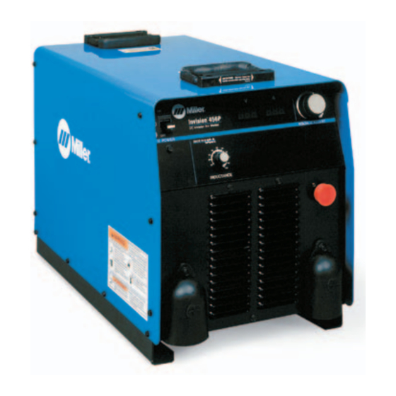
Invision 456P And
R
XMT 456 CC/CV
(230/460 And 575 Volt Models)
OM-2232
2005−10
Processes
Processes
Invision 456P:
MIG (GMAW) and Pulsed MIG
(GMAW-P) Welding
Flux Cored (FCAW) Welding
XMT 456 CC/CV:
Multiprocess Welding
Description
Invision 456P:
XMT 456 CC/CV:
R
File: MIG (GMAW)
202 221J
Advertisement
Table of Contents
Troubleshooting


Need help?
Do you have a question about the Invision 456P and is the answer not in the manual?
Questions and answers