Table of Contents
Troubleshooting

Related Manuals for Miller XR - Pistol - Pro


Summary of Contents for Miller XR - Pistol - Pro
- Page 1 OM-254 824D 2012−07 Processes MIG (GMAW) Welding Description Semi-Automatic, Air/Water- Cooled, MIG (GMAW) Welding ™ XR - Pistol - Pro (Air And Water-Cooled Guns) File: MIG (GMAW) Visit our website at www.MillerWelds.com...
- Page 2 We know you don’t have time to do it any other way. That’s why when Niels Miller first started building arc welders in 1929, he made sure his products offered long-lasting value and superior quality.
-
Page 3: Table Of Contents
TABLE OF CONTENTS SECTION 1 −SAFETY PRECAUTIONS FOR GMAW WELDING GUNS − READ BEFORE USING ..1-1. Symbol Usage ............... . 1-2. -
Page 5: Section 1 −Safety Precautions For Gmaw Welding Guns − Read Before Using
SECTION 1 −SAFETY PRECAUTIONS FOR GMAW WELDING GUNS − READ BEFORE USING SR7 (MIG) 2011-10 Protect yourself and others from injury — read, follow, and save these important safety precautions and operating instructions. 1-1. Symbol Usage DANGER! − Indicates a hazardous situation which, if Indicates special instructions. -
Page 6: Proposition 65 Warnings
1-3. Proposition 65 Warnings Welding or cutting equipment produces fumes or gases This product contains chemicals, including lead, known to which contain chemicals known to the State of California to the state of California to cause cancer, birth defects, or other cause birth defects and, in some cases, cancer. -
Page 7: Utilisation
SECTION 2 − MESURES DE SÉCURITÉ VISANT LES PISTOLETS DE SOUDAGE GMAW − À LIRE AVANT UTILISATION SR7(MIG)_2011−10fre Pour écarter les risques de blessure pour vous−même et pour autrui — lire, appliquer et ranger en lieu sûr ces consignes relatives aux précautions de sécurité... -
Page 8: Proposition Californienne 65 Avertissements
LES PIÈCES CHAUDES peuvent LES FILS DE SOUDAGE peuvent provoquer des brûlures. provoquer des blessures. D Laisser refroidir le pistolet avant de le toucher. D Éloigner les mains et le corps de la buse du pis- D Ne pas toucher d’objets métalliques chauds. tolet après avoir appuyé... -
Page 9: Section 3 − Definitions
SECTION 3 − DEFINITIONS 3-1. Additional Safety Symbols And Definitions Some symbols are found only on CE products. Warning! Watch Out! There are possible hazards as shown by the symbols. Safe1 2012−05 3-2. Miscellaneous Symbols And Definitions Primary Voltage Volts Primary Current Amperes Degree Of... -
Page 10: Section 4 − Introduction
SECTION 4 − INTRODUCTION 4-1. Gun Specifications Model Welding Output Range Electrode Wire Feed Net Weight Wire Diameter Speed Range (Torch Only) Capacity XR-Pistol-Pro 200 A at 100% Duty Cycle .030 To 1/16 in. 70 To 900 ipm 2.2 lb (1 kg) (Air-Cooled) 250 A at 60% Duty Cycle (0.8 To 1.6 mm) -
Page 11: Section 5 − Installation
SECTION 5 − INSTALLATION Be sure that contact tip, liner, and drive rolls are correct for wire size and type. See Parts List to change parts as needed. 5-1. Connections With A Constant Voltage (CV) Or Constant Current/Constant Voltage (CC/CV) Welding Power Source Having A 14-Socket Receptacle Or A Integrated Welding Power Source Having A 10-Socket Receptacle Ref. -
Page 12: Air-Cooled Gun Connections
5-2. Air-Cooled Gun Connections Left Side Ref. T0017 / 246 218-A Gun Control Cable Gun Bushing Loosen gun securing knob and insert gun power pin through gun bushing until it Insert plug into Gun Control receptacle, and Gun Securing Knob bottoms against drive casting. -
Page 13: Water-Cooled Gun Connections
5-3. Water-Cooled Gun Connections Turn on coolant supply before welding or gun will be dam- aged. Gun Control Cable Insert plug into Gun Control receptacle, and tighten threaded collar. Gun Power Pin Gun Securing Knob Gun Bushing Drive Casting Loosen gun securing knob, and insert gun power pin through gun bushing until it bottoms against drive casting. -
Page 14: Millermatic 350/350P Water Cooled Gun Connections
5-4. Millermatic 350/350P Water Cooled Gun Connections Ref. T0021 Tools Needed: 9/16 in. Water In Hose bottoms against block. Tighten knob. Close Turn on coolant supply before welding and latch door. or gun will be damaged. Connect to coolant supply with supplied Water Out Hose Coolant Supply coupler and water hose (left-hand threads). -
Page 15: Threading Welding Wire Through Millermatic 350/350P
5-5. Threading Welding Wire Through Millermatic 350/350P Wire Spool Welding Wire Inlet Wire Guide Drive Roll Intermediate Wire Guide Outlet Wire Guide Pressure Adjustment Knob Gun Conduit Cable Lay gun cable out straight. Tools Needed: Hold wire tightly to keep it IMPORTANT! from unraveling. -
Page 16: Threading Welding Wire Through Xr-Control Feeder
5-6. Threading Welding Wire Through XR-Control Feeder Cable Assembly Lay cable assembly out straight. Jog Switch Tools Needed: Push Jog switch up to feed wire through cable assembly. Torque Switch Select proper push feeder torque set- ting for wire size being used. Use low torque for .030 in. -
Page 17: Adjusting Tension At Feeder
5-7. Adjusting Tension At Feeder Tools Needed: Hold wire tightly to keep it from unraveling. 6 in. (150 mm) Tension Arm Pull and hold wire; cut off end. Open tension arm. Install proper size drive rolls. Thread wire thru inlet guide, along drive roll groove, and into wire conduit. -
Page 18: 10-Pin Plug Information
5-8. 10-Pin Plug Information Pin* Pin Information Electrode sense lead Motor 0 to +24 volts DC with respect to pin C Trigger Motor Common Trigger Wire speed Ref. +9 volts DC Wire speed com Wire speed 0 to +9 volts DC with respect to pin H Gun sensing resistor with respect to pin H Not used 5-9. -
Page 19: Threading Welding Wire Through Gun
5-10. Threading Welding Wire Through Gun Refer to wire feeder manual for instructions on feeding wire through feeder. Pressure Arm Lever To release drive roll pressure, pull back on pressure arm lever. While pulled back, shift to left onto shoulder to lock into place. Welding wire is electrically live when gun trigger is used to jog wire. -
Page 20: Section 6 − Operation
SECTION 6 − OPERATION 6-1. Gun Controls Trigger Press trigger to energize welding power source contactor (if applicable), start shielding gas flow, and begin wire feed. Wire Speed Control Use control to fine adjust wire feed speed set on wire feeder Weld Speed control. -
Page 21: Shielding Gas
Coolant No. 043 809**; Distilled Or Deionized Water OK ° ° Above 32 F (0 Coolant *HF: High Frequency Current ° ° **MILLER coolants protect to -37 F (-38 C) and resist algae growth. Ref. 150 755-A OM-254 824 Page 17... -
Page 22: Section 7 − Maintenance & Troubleshooting
SECTION 7 − MAINTENANCE & TROUBLESHOOTING Disconnect power Maintain more often before maintaining. during severe conditions. 3 Months Clean Replace Replace Damaged Or Damage Tighten Unreadable Gas Hose Weld Labels Terminals Repair Or Replace Cracked Cables And Cords 6 Months Blow Out Or Clean Vacuum Inside... -
Page 23: Changing Gun Contact Tip
7-2. Changing Gun Contact Tip Remove nozzle Nozzle FasTip Unscrew FasTip. Install new FasTip. Ref. 150 437-A 7-3. Gun Drive Assembly Maintenance Lever Arm Remove pressure on wire by pulling lever arm forward. Pull to left to lock into place. Retract wire onto spool. -
Page 24: Replacing Head Tube Liner
7-4. Replacing Head Tube Liner Turn Off coolant supply before removing head tube water-cooled gun. The standard head tube liner (yellow) will accommodate wire diameters from 3/64 in. - 1/16 in. wire size. When changing wire size, change gun drive roll. Cover Head Tube Remove head tube from gun. -
Page 25: Troubleshooting
7-6. Troubleshooting Disconnect power before troubleshooting. Trouble Remedy Pressing gun trigger does not energize Secure plug from gun control cable into Gun Control receptacle on feeder (see Section 5-2 or 5-3 as applicable). feeder. Welding wire is not energized. Shielding gas does not flow. Have nearest Factory Authorized Service Agent check optional water flow switch, if applicable. - Page 26 Notes OM-254 824 Page 22...
-
Page 27: Section 8 − Electrical Diagrams
SECTION 8 − ELECTRICAL DIAGRAMS Ref. 256 014 Figure 8-1. Circuit Diagram For XR Pistol Pro Gun OM-254 824 Page 23... -
Page 28: Section 9 − Parts List
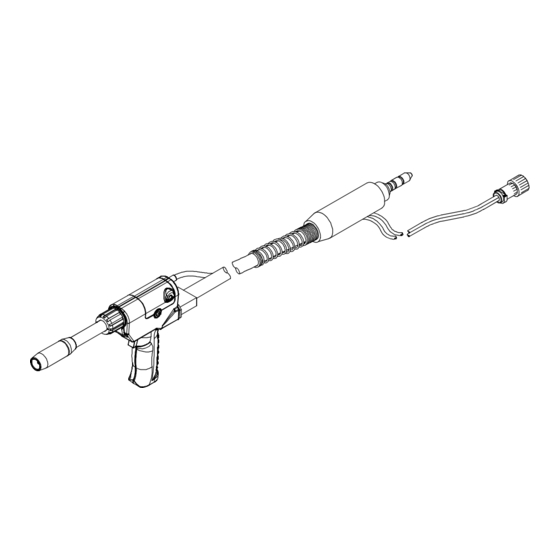
SECTION 9 − PARTS LIST 52 49 67 66 9 10 Hardware is common and not available unless listed. T0028 Figure 9-1. Exploded View Of XR - Pistol - Pro Gun OM-254 824 Page 24... - Page 29 Item Part Description Quantity Figure 9-1. Exploded View Of XR - Pistol - Pro Gun ... . . 257 353 Kit, Handle XR Pistol Pro/Plus ........
- Page 30 Part Description marking Quantity Figure 9-1. Exploded View Of XR - Pistol - Pro Gun (Continued) ... . 255 716 Kit, Head Tube Assy (Air) AP/PP 180Deg 4In......
- Page 31 Hardware is common and not available unless listed. T0030 Figure 9-2. (Water) Head Tube Assembly Of XR - Pistol - Pro Gun Item Part Description Quantity Figure 9-2. (Water) Head Tube Assembly Of XR - Pistol - Pro Gun (Figure 9-1 Item 42) .
- Page 32 Hardware is common and not available unless listed. T0029 Figure 9-3. (Air) Head Tube Assembly Of XR - Pistol - Pro Gun Item Part Description Quantity Figure 9-3. (Air) Head Tube Assembly Of XR - Pistol - Pro Gun (Figure 9-1 Item 42) .
- Page 33 Notes OM-254 824 Page 29...
-
Page 34: Section 10 − Parts List Including Consumables
SECTION 10 − PARTS LIST INCLUDING CONSUMABLES Item Number A/C OUTER 1805 (M1366) W/C OUTER 4.0” STRAIGHT A/C (230 679) 1805 (255 716) .030−1/16” WIRE (M1369) (229 670) COLLARED 4.0” STRAIGHT W/C INSULATOR (255 717) (230 678) (232 284) Ref. T0031 Figure 10-1. - Page 35 Item Part Description Quantity Consumables Flowchart (Continued) Table 10-2. Heavy Duty FasTipt Contact Tips* ♦206 185 ... .030 in. (0.8 mm) ........... ♦206 186 .
- Page 36 Notes...
- Page 37 Notes Start Your Professional Over 80,000 trained 400 Trade Square East, Troy, Ohio 45373 Welding Career Now! since 1930! 1-800-332-9448 www.welding.org...
- Page 38 Notes MATERIAL THICKNESS REFERENCE CHART 24 Gauge (.025 in.) 22 Gauge (.031 in.) 20 Gauge (.037 in.) 18 Gauge (.050 in.) 16 Gauge (.063 in.) 14 Gauge (.078 in.) 1/8 in. (.125 in.) 3/16 in. (.188 in.) 1/4 in. (.25 in.) 5/16 in.
- Page 39 Effective January 1, 2012 (Equipment with a serial number preface of MC or newer) This limited warranty supersedes all previous Miller warranties and is exclusive with no other Warranty Questions? guarantees or warranties expressed or implied. LIMITED WARRANTY − Subject to the terms and conditions 90 Days —...
- Page 40 Contact the Delivering Carrier to: File a claim for loss or damage during shipment. For assistance in filing or settling claims, contact your distributor and/or equipment manufacturer’s Transportation Department. © ORIGINAL INSTRUCTIONS − PRINTED IN USA 2012 Miller Electric Mfg. Co. 2012−01...
Need help?
Do you have a question about the XR - Pistol - Pro and is the answer not in the manual?
Questions and answers