Tektronix PHASER 840 Quick Reference Manual
Color laser printer
Hide thumbs
Also See for PHASER 840:
- Service manual (207 pages) ,
- Advanced features and troubleshooting manual (152 pages) ,
- Troubleshooting manual (152 pages)
Table of Contents
Advertisement
Quick Links
P H A S E R ® 8 4 0
C O L O R L A S E R P R I N T E R
S e rvic e Qu i c k Re f e r e n c e G u i d e
Warning
The following servicing instructions are for
use by qualified service personnel only. To
avoid personal injury, do not perform any
servicing other than that contained in
operating instructions unless you are qualified
to do so.
This printing: May 1998
071-0388-00
Advertisement
Table of Contents

Related Manuals for Tektronix PHASER 840


Summary of Contents for Tektronix PHASER 840
- Page 1 P H A S E R ® 8 4 0 C O L O R L A S E R P R I N T E R S e rvic e Qu i c k Re f e r e n c e G u i d e Warning The following servicing instructions are for use by qualified service personnel only.
- Page 2 © Copyright 1998 by Tektronix, Inc., Wilsonville, Oregon. Printed in the United States of America. All rights reserved. Contents of this publication may not be reproduced in any form without permission of Tektronix, Inc. ® ® ® Tektronix , Phaser...
-
Page 3: User Safety Summary
User safety summary Terms in manual CAUTION Conditions that can result in damage to the product. WARNING Conditions that can result in personal injury or loss of life. Power source: For 110 VAC printers, Do not apply more than 130 volts RMS between the supply conductors or between either supply conductor and ground. - Page 4 Symbols as marked on product: DANGER high voltage: Protective ground (earth) terminal: Use caution. Refer to the manual(s) for information: WARNING: If the product loses the ground connection, usage of knobs and controls (and other conductive parts) can cause an electrical shock. Electrical product may be hazardous if misused.
-
Page 5: Table Of Contents
Contents General Information Phaser 840 printer overview Solid inks About RAM upgrades Memory considerations Print engine assemblies The main board Combination sensors and their meanings Media tray type sensing Front panel Rear panel Regulatory specifications Error Codes and Messages Rear panel LEDs error codes... - Page 6 Adjustments Process belt tension adjustment Exit roller drive belt tension adjustment Y-axis belts tension adjustment Printhead-to-drum spacing adjustment Cap/wipe/purge assembly belt adjustments Drum position encoder gap Transfix roller pressure spring adjustment X-axis scale adjustment Vacuum check Phaser 840 Color Printer...
- Page 7 Cleaning and Maintenance Cleaning Cleaning Page Vacuum Drum temperature sensor Maintenance Maintenance roller Waste tray Lubrication Inspection Resetting NVRAM Resetting NVRAM Key FRU Removal and Replacement Main board Power supply Power control board Paper/drum heater Upper feed roller assembly Drum/transfix assembly Drum position sensor assembly Printhead X-axis motor and drive assembly...
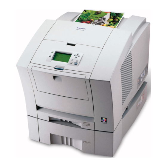
- Page 8 Figures The Phaser 840 printer (shown with optional High-capacity Paper Tray Assembly) 1 Internal features of the print engine 6 Circuit boards of the print engine (right front view) 7 Circuit boards of the print engine (left-rear view) 8 The printer’s I...
- Page 9 Removing the Y-axis belt drive assembly 105 Removing the cap/wipe/purge assembly 107 Cabinet FRUs 111 Imaging FRUs 113 Paper path FRUs 115 Motors and fans FRUs 117 Circuit boards FRUs 119 Solenoids and clutches FRUs 121 Gears and belts FRUs 123 Sensors and flags FRUs 125 High-capacity Paper Tray 127 Print engine wiring diagram 145...
- Page 10 Motors and fans FRUs 116 Circuit board FRUs 118 Solenoid and clutches FRUs 120 Gears and belts FRUs 122 Sensors and flags FRUs 124 High-capacity Paper tray FRUs 126 Service tools 128 Supplies and accessories 128 Phaser 840 Color Printer...
-
Page 11: General Information
General Information This service guide contains information useful to verify operation, troubleshoot, repair, adjust, and maintain a Tektronix Phaser® 840 Color Printer. This guide includes a Field Replacement Unit list. Topics such as printer theory of operation, detailed removal/replacement procedures, configuration page details, and verifying printer operation are located on the companion Color Printer Service &... -
Page 12: Phaser 840 Printer Overview
The Phaser 840 Extended printer. The Extended Features option has all the features of the Phaser 840 Plus printer but includes additional RAM to bring the printer to 128 Mbytes of RAM. It also includes a High-capacity Paper Tray and an internal IDE hard drive. -
Page 13: Solid Inks
Because Tektronix' proprietary solid inks bleed much less than ordinary liquid inks, they allow the printer to print brilliant colors on plain paper. Each Tektronix solid-ink printer inks are especially formulated for that printer; the inks are not interchangeable. -
Page 14: Memory Considerations
50 records 500 records. 5000 5000 records with records with optional included hard drive hard drive Frame buffer (lower 1 Letter size image 1 Letter-size image 2 Letter-size images print resolutions can provide additional frame buffer space) Phaser 840 Color Printer... - Page 15 64 Mbytes Mem slot 1: SDRAM/parity/64 MB/KMM366S823BTL-G0 Mem slot 2: empty This is a list of SDRAM DIMMs that are branded for use by Tektronix in this printer at the time this guide was published: Size Maker Part Number 32 Mbytes...
-
Page 16: Print Engine Assemblies
Print engine assemblies Ink load Cap/wipe/purge assembly Printhead assembly Drum Transfix roller Process motor Paper/ drum heater X-axis drive Y-axis and motor motor Paper feed motor 0388-02 Internal features of the print engine Phaser 840 Color Printer... -
Page 17: Circuit Boards Of The Print Engine (Right Front View)
Six circuit boards support the printer’s electronics. Two boards, called I/ O boards, support the front panel, solenoids and sensors. The main board contains the printer’s CPU processor, RAM and ROM. The power control board distributes power supply voltages to the other printer boards as well as drive many printer motors. -
Page 18: Circuit Boards Of The Print Engine (Left-Rear View)
Printhead drive board Internal hard drive Drum Maintenance counter EEPROM Network card Power control board Power supply I/O board left Main board 0388-04 Circuit boards of the print engine (left-rear view) Phaser 840 Color Printer... -
Page 19: The Printer's I 2 C Bus
An internal data bus, called the I C bus, connects all I/O boards to the main board. Through this single bus, the main board can “poll” the I/O boards for the state of the printer’s sensors as well as actuate the printer’s solenoids. This data bus greatly simplifies the wiring that would otherwise be required for monitoring numerous sensors and solenoids. -
Page 20: Printhead Maintenance System Of The Print Engine
The system consists of a vacuum pump assembly, the cap/wipe/purge assembly and the cap/wipe/ purge carriage drive. Cap/wipe/purge carriage drive Vacuum pump assembly Cap/wipe/purge assembly 0388-06 Printhead maintenance system of the print engine Phaser 840 Color Printer... -
Page 21: Sensors And Switches On The Right Side Of The Print Engine
Sensors in the printer provide information to the main board to determine the state of the printer. The printer monitors the positions of some of the movable assemblies, such as the drum, as well as the temperature of many other assemblies, such as the printhead, paper preheater and the drum. -
Page 22: Sensors And Switches On The Left Side Of The Printer
Drum encoder sensor Preheater exit sensor Process gear position sensor Transfix roller Preheater exit sensor Preheater located on inside wall of drum/transfix frame Drum 0388-34 Sensors and switches on the left side of the printer Phaser 840 Color Printer... -
Page 23: Solenoids And Clutches On The Print Engine
Caution The actual position of some printer assemblies, such as the printhead or the cap/wipe/purge assembly, cannot be ascertained at all times. The printer records, in NVRAM, where it last positioned such assemblies each time it moves them. If, after power-down or a power interruption, the assemblies are manually repositioned, the printer erroneously assumes that the assemblies are in the position it last left them. -
Page 24: The Main Board
ID chip, an 8-pin socketed IC. All these socketed components should be transferred to a replacement main board to maintain customer-unique settings. Boot ROM/ RAM DIMMs SCSI riser Printer ID board NV RAM/ Real Time Clock Code ROM DIMM 0388-09 Features of the main board Phaser 840 Color Printer... -
Page 25: Combination Sensors And Their Meanings
Combination sensors and their meanings Combinations of sensors are used by the printer to determine the type of standard (or upper) media tray installed in the printer. Media tray type sensing The combinations of the three tray sensors inform the print engine what type of media tray is installed. -
Page 26: Front Panel
Holding the Left arrow while turning off the printer will confirm the printhead is correctly parked by flashing both front panel LEDs. Turning the printer on with the rear panel DIP 2 in the “down” position, allows access to the front panel during the warm-up cycle. Phaser 840 Color Printer... -
Page 27: Printer Front Panel
The topic “Resetting NVRAM” on page 83 explains how to use the front panel buttons to reset the NVRAM to its factory-default values. Navigation buttons Power READY TO PRINT Error Help Select button button 0388-10 Printer front panel Service Guide... -
Page 28: Rear Panel
Standard parallel (high-density connector), IEEE 1284C Twisted Pair (10BaseT) Ethernet connector A Universal Serial Bus port Optional SCSI high-density connector (hard disk drive or Tektronix approved scanner). A special 5-pin connector accommodates a service RS-232 cable from a PC or Macintosh computer running PC-based diagnostics. -
Page 29: Printer Rear Panel
Switches Four DIP switches allow you to reset the printer or place the printer in different operating modes. Table 2 Rear panel DIP switch settings Function Switch 1 Switch 2 Switch 3 Switch 4 Normal operating mode Service mode DOWN Reset printer DOWN Manufacturing mode (Bypass... -
Page 30: Physical Dimensions
Unrestricted to replace trays and clear paper jams Rear: 10.2 cm (4 ins.) Bottom: No obstruction under printer that could block its cooling vents. Mounting surface Within 3 degrees of horizontal with all four feet in contact with flatness: the surface. Phaser 840 Color Printer... - Page 31 Functional specifications Characteristic Specification Printing process Solid ink-jet onto plain paper. Color medium Cyan, magenta, yellow and black ink sticks, each shape- coded. The printer uses the subtractive color system to produce the colors red, green, and blue. Addressability Selectable 273 x 300, 409 x 409, 491 x 982 or 600 x 1200 dots-per-inch (horizontal and vertical).
- Page 32 EN61000-4-3:1995-02 RF Field Immunity EN61000-4-2:1995-01 ESD (Electo-Static Discharge) EN61000-4-4:1995-01 Fast Burst Transient EN61000-4-5:1995-02 Line Surge EN61000-4-6:1996-03 RF conducted Immunity EN61000-4-11:1994-06 Voltage Dips and Interruptions EN61000-3-3:1994-12 Flicker 73/23/EEC Low Voltage Directive 89/336/EEC Electromagnetic Compatibility Directive 89/392/EEC Machinery Directive Phaser 840 Color Printer...
- Page 33 Environmental specifications Characteristic Specification Temperature ° ° Operating to 32 C (50 to 90 ° ° Storage and to 60 C (-22 to 140 shipping Humidity Operating 10 to 80% relative humidity, non-condensing Non-operating 10 to 95% relative humidity, non-condensing Altitude °...
-
Page 34: Regulatory Specifications
Regulatory specifications The Phaser 840 Color Printer is in conformance with the following regulatory standards: FCC Part 15 Class B (for 115 VAC equipment) EN55022 (CISPR 22) Class B VCCI (CISPR 22) Class B EN61000-3-2 Flicker on AC Mains Susceptibility... -
Page 35: Error Codes And Messages
Error Codes and Messages Rear panel LEDs error codes The rear panel LEDs are located on each side of the rear panel DIP switches. The left LED represents the operation of the PostScript firmware. The right LED represents operation of the main board’s print engine firmware. During the POST tests, the two LEDs toggle back and forth for each successful pass through each SDRAM test. - Page 36 4 bytes in the VxWorks section of the NVRAM. EPROM This test reads in the first 24 bytes from the EPROM then verifies that the Tektronix Ethernet address 0x08, 0x00, and 0x11 has been copied into three locations. Mariner ASIC This test reads and verifies the version level of the...
- Page 37 Table 3 Main board power-up self-test error codes Left LED Meaning Details flashes Long flash =5 Short flash=1 2L+1S=11 none Ethernet This test verifies the functionality of the Ethernet 100BaseT LAN Controller chip. Any test failures with this Option Card component are treated as non-fatal errors with the error information written to the Start Page.
-
Page 38: Error Messages
CAM_BEGIN down, oil roller down, the drum maintenance cam home sensor should have been TRUE and was instead FALSE. Check the drum maintenance cam solenoid, clutch, home sensor, and related hardware. Phaser 840 Color Printer... - Page 39 Table 4 Front panel and fault history log error codes and messages Error code Meaning 4,010.40 (0x240A) During the drum maintenance cycle, when the drum PC_DEV_FAULT_DM_ maintenance cam position should have been at blade CAM_BU_WU up/oil roller up, the drum maintenance cam home sensor should have been FALSE and was instead TRUE.
- Page 40 6,000: X axis 6,000.41 (0x3400): X axis motor over/under current. Indicates motor coil(s) XA_FAULT_MCURRENT are open, or shorted, or the motor fuse has opened. 7,000: Process motor Phaser 840 Color Printer...
- Page 41 Table 4 Front panel and fault history log error codes and messages Error code Meaning 7,001.43 (0x3c01): The electronics report an error while operating the motor PM_FAULT_AUXILIARY in the auxiliary feeder (the optional High-capacity paper Tray) MOTOR_ERROR 7,002.44 (0x3c02): The process motor stalled during operation. This has PM_FAULT_PROCESS_ several possible causes, depending on what the process MOTOR_STALL...
- Page 42 The right jet stack heater is not heating at all, or is not TCH_JS_RIGHT_SLOW heating as quickly as it should. 13,033.45 (0x6c21): The thermistor in the reservoir appears to be open. TCH_RESERVOIR_ Replace the printhead. OPEN Phaser 840 Color Printer...
- Page 43 Table 4 Front panel and fault history log error codes and messages Error code Meaning 13,034.46 (0x6c22): The thermistor in the reservoir appears to be shorted. TCH_RESERVOIR_ Replace the printhead. SHORT 13,035.47 (0x6c23): The reservoir heater is running away. Unplug the printer TCH_RESERVOIR_HOT NOW! 13,036.48 (0x6c24):...
- Page 44 22,707,0C DECLARED Media too long at exit tray 22,708,0C DECLARED Media too short at exit tray 22,721,0C DECLARED Media not staged at preheater entry in time for transfix 22,722, 0C DECLARED Media jam at stripper fingers Phaser 840 Color Printer...
- Page 45 Table 4 Front panel and fault history log error codes and messages Error code Meaning 22,901,0C DOOR The front access door is opened EVENT 22,902, 0C DOOR The top, stripper, access door is opened EVENT 22,LSS,TC: Media jams L indicates the location SS indicates sensor location: of the jam Usually because of an opened door...
- Page 46 Phaser 840 Color Printer...
-
Page 47: Troubleshooting
Troubleshooting System power-up sequence The following lists the chain of events that occur when you turn on a printer. You can follow this list as one means of determining if the printer is operating correctly. The exact chain of events depends upon where the printer “believes” the printhead is positioned. - Page 48 The printhead tilts forward and a purge cycle begins. A cleaning page is printed. The front panel displays a message that the printer is initializing and then ready. The print engine is initialized. Phaser 840 Color Printer...
-
Page 49: Verifying Main Board Cpu Operation
Verifying main board CPU operation If the printer does not power up (rear fan is off and power-up diagnostics LEDs are off), go to the topic, “Verifying power supply operation” below. Observe the rear panel LEDs located on each side of the rear panel DIP switches. -
Page 50: Measuring Power Supply Voltages
AC power may be applied to the heater without the printer even being turned on, resulting in a thermal runaway condition. If the fuses are functional, but the printer's power supply does not output DC voltages, proceed to the topic, “Testing for shorted drivers” on page 41. Phaser 840 Color Printer... -
Page 51: Testing For Shorted Drivers
Testing for shorted drivers Turn off the printer. Disconnect the +40 DC loopback connector (the 4-pin connector with the two loopback wires) from J250 at the top of the power control board. (This isolates the Y-axis motor, process motor, X-axis motor, paper feed motor, vacuum pump, solenoids and clutches). -
Page 52: Testing For A Shorted Motor
Resistance (approximately) Process motor 3 ohms Y-axis motor 2 ohms X-axis motor 60 ohms/phase Paper feed motor <1 ohms/phase Maintenance drawer camshaft electric 10. ohms clutch Paper-pick electric clutch 10 ohms Transfix cam solenoid 45 ohms Phaser 840 Color Printer... -
Page 53: Media Jams And The Paper Path
Media jams and the paper path Required tools TORX screwdriver and tips Digital multi-meter Jams fall into the following four categories: Media-based problems Paper-pick errors Paper-feeding errors Paper-ejecting errors Media-based problems Check that the correct type of media is being used. Fanning the media eliminates its tendency to double-pick. -
Page 54: Print Transfer Jams
Ensure that the transfix roller rotates during the transfix process. Test the sensors in the paper path. Look for damaged or non-operating sensor flags. Check the transfix solenoid and its cam. Ensure they operate correctly and are properly lubricated. Phaser 840 Color Printer... -
Page 55: Checking The Process Motor And Drive Train
Checking the process motor and drive train Determine if the process motor runs. If it does not rotate, go to Step 2. If it does rotate, go to Step 5. Measure to determine if +40 VDC is being supplied to the motor. If it is, go to Step 3. -
Page 56: Printing And Print Quality Problems
Ensure that no wiring harnesses are interfering with the horizontal slewing of the printhead. In such a case, the streaks or lines should be 0388-41 parallel and evenly spaced. Check for media in the exit path. Phaser 840 Color Printer... -
Page 57: Missing Ink Or Light Colored Ink Band Running Length Of Print
The x-axis drive is not functioning correctly. If the X-axis drive does not slew the printhead smoothly and evenly during printing, vertical lines appear in the print. Print Service Test Print 1 “X-axis” to reveal an X-axis problem. Replace the X-axis drive, if indicated. Replace the x-axis drive assembly. -
Page 58: Scratches Parallel To The Long Axis Of Printing, Particularly With Film
Run diagnostics to ensure that printer temperatures are in tolerance. Ensure that the drum heater is properly positioned. Print using a smoother, laser quality paper. Some recycled paper brands may be too rough. 0388-44 Phaser 840 Color Printer... -
Page 59: Color Is Uneven
Dark rectangular marks on transparency film can be caused by an accumulation of paper dust and oil on the feed rollers. Run 2 or 3 sheets of blank paper through the printer to clean the rollers or manually clean the rollers. Replace the power control board. -
Page 60: Fuzzy Text
66. Verify the drum temperature using PC-based diagnostics. Ensure the drum temperature sensor is properly positioned. Verify the paper preheater temperature using PC-based diagnostics. If the problem persists, replace the printhead. 0388-47 Phaser 840 Color Printer... -
Page 61: Poor Small Text Resolution
Poor small text resolution Small characters appear heavy and “plug up.” Verify the drum temperature using PC-based diagnostics. Ensure the drum temperature sensor is properly positioned. Inspect and clean the drum temperature sensor. Ensure that the X-axis drive system is correctly assembled and lubricated. -
Page 62: Variation Of Density On Second Side Of Print
Are the drum maintenance cam roller and electric clutch operating correctly? Test them using PC- based diagnostics. Ensure the left and right drum maintenance actuators operate correctly when lifted by the cams of the drum maintenance cam roller. 0388-50 Phaser 840 Color Printer... -
Page 63: Oil Streaks On Print
Oil streaks on print Oil stains the edge of the print. Inspect the drum maintenance drawer. Is the wiper blade damaged? If necessary, replace the drum maintenance drawer. Are the drum maintenance cam roller and electric clutch operating correctly? Test them using PC- based diagnostics. -
Page 64: Incomplete Image Transfer To Paper
Ensure the drum temperature sensor is properly positioned and has no contamination between it and the drum surface. Verify the paper preheater temperature using PC-based diagnostics. Try a different paper, if a specialty coated paper is being used. Phaser 840 Color Printer... -
Page 65: Ink Smears Of First Side Of Duplex Print
Ink smears of first side of duplex print Preheater temperature is too high. Verify the paper preheater temperature using PC-based diagnostics. Replace the paper preheater, if necessary. 0388-53 Repeating print defects on print The distance between each artifact of a repeating image defect reveals which imaging component is causing the defect. -
Page 66: Banding Parallel To Long Edge Of Print
Inspect the maintenance drawer wiper blade. Replace the maintenance drawer, if necessary. The transfix spring pressure is incorrect. Perform the procedure “Transfix roller pressure spring adjustment” on page 72. Replace the drum/transfix assembly. 0388-56 Phaser 840 Color Printer... -
Page 67: Image Is Offset Or Cut Off
The printer indicates it is receiving data, but no print comes out of printer or the printer goes back to Ready to Print mode without printing an image. Make sure that the correct Phaser 840 printer icon was selected in the Chooser. Try printing the job again. Try printing a different file or from a different application. -
Page 68: Image Prints In Black-And-White
In the Print dialog box, make sure that the Color/Grayscale option has been selected. Make sure that the Phaser 840 printer icon was selected in the Chooser. Try printing the job again. Check the version of your LaserWriter driver to ensure that it is version 6.0.x or higher. -
Page 69: Adjustments
Adjustments Bypass mode (manufacturing mode) Bypass mode allows you to access the front panel menus (bypassing the engine and PostScript initializing processes) without having to wait for the printhead to warm up. This way, you can reset NVRAM or read fault codes immediately. Meanwhile, the printer continues to warm-up and initialize “in the background.”... -
Page 70: Hidden Service Menu
Scroll to the Printer Configuration menu. While holding the Left arrow button; press Select. The front panel will display the complete menu list. Exiting from the submenu returns the printer to the short version of the Printer Configuration menu. Phaser 840 Color Printer... -
Page 71: Printing Service Test Prints
Printing service test prints Turn on the printer. Allow the printer to complete its power-up self-tests. The front panel displays: READY TO PRINT Scroll to the Troubleshooting menu and press Select. Press and hold the Left arrow button. While holding the Left arrow button, press Select to enter the hidden service menu. -
Page 72: Adjustments
0.7 kgs (1.5 lbs) and then tighten the tensioner in place. Do not over-tension the belt. Press here to set belt deflection Process belt tensioner 0388-28 Setting process belt tension Reinstall the left side panel. Phaser 840 Color Printer... -
Page 73: Exit Roller Drive Belt Tension Adjustment
Exit roller drive belt tension adjustment Turn off the printer and remove the left-side cabinet panel. To adjust the belt tension, loosen the exit roller drive belt tensioner. With a spring scale, press downward on the idler tensioner of the exit roller drive belt with a pressure of 0.5 kg (1 lb) then tighten the tensioner in place. -
Page 74: Y-Axis Belts Tension Adjustment
Use a distinct color if the pulleys have been previously marked. Loosen the 3 mounting screws until the bracket slides freely on the chassis and then re-tighten the screws to 30 in.-lb. Release the tension tool's lever arm and remove the tool. Phaser 840 Color Printer... -
Page 75: Setting The Y-Axis Belt Tension
Reassemble the printer and make a test print. Tighten screws after setting tension Mark the pulleys Attach tension Y-axis belt tool to keyholes assembly Pull lever arm to set tension 0388-30 Setting the Y-axis belt tension Service Guide... -
Page 76: Printhead-To-Drum Spacing Adjustment
Place indicator bracket over hex-screw Attach digital gap indicator to side frame Attach bracket in forward most position to tilt arm. Ensure a flush fit. 0388-31 0388-36 Attaching the digital gap indicator Phaser 840 Color Printer... -
Page 77: Spacing The Printhead To The Drum
At the right side of the printhead, insert the RIGHT printhead spacer between the printhead and the drum. Check the indicator; for a “hot adjustment” it should read 0.0070 0.0010 inches, and 0.0030 0.0010 inches for a “cold” adjustment. Adjust the printhead’s spacing adjustment screws until the indicator reads the correct value. -
Page 78: Cap/Wipe/Purge Assembly Belt Adjustments
Repeat until the right-side timing lock’s pointer points at the index mark on the right-side frame as the left-side timing belt lock’s pointer points between its index marks on the left-side frame. Phaser 840 Color Printer... -
Page 79: Aligning (Timing) The Cap/Wipe/Purge Assembly Drive Belts
Belt lock Index mark on right frame Unlock Latch For new belt, break off actuator on left-side belt lock Left belt lock: align pointer between two index marks Idler pulley Lock Right Leave gap cap/wipe/purge between latch assembly belt and belt tensioner 0388-32 Aligning (timing) the cap/wipe/purge assembly drive belts... -
Page 80: Drum Position Encoder Gap
firmly against the encoder gap tool. Holding the gap tool in place, with a small, flatblade screwdriver, slide the encoder wheel’s retaining spring into the encoder wheel’s groove. Remove the gap tool. Reassemble the printer and make a test print. Phaser 840 Color Printer... -
Page 81: Setting The Drum Position Encoder Gap
Gap tool Groove Retaining spring Drum position sensor assembly 0388-33 Setting the drum position encoder gap Service Guide... -
Page 82: Transfix Roller Pressure Spring Adjustment
If wrinkling still occurs on the same side, repeat Step 6 and 7. Do not adjust the set screws more than 3/8 of a revolution from their original position. Any adjustment beyond this point results in ink adhesion problems. If wrinkling continues to occur, replace the drum/transfix assembly. Phaser 840 Color Printer... - Page 83 Original registration mark 3/8 turn 3/8 turn maximum maximum Tension spring set screws 0388-38 Adjusting the transfix roller pressure springs Service Guide...
-
Page 84: X-Axis Scale Adjustment
Select the menu item Print X-axis calibration pattern to verify the adjustment. Repeat the adjustment, if necessary. Increase scale Correct Decrease scale adjust to raise adjust to lower center bars center bars 0388-67 Adjusting the x-axis scale adjustment Phaser 840 Color Printer... -
Page 85: Vacuum Check
Vacuum check Tools required Magnetic screwdriver Vacuum gauge T-20 TORX tip T-15 TORX tip PC diagnostics Use this check to verify the actions of the vacuum pump and the solenoid valve. In addition, you can determine if the cap/wipe/purge assembly is sealing properly against the printhead faceplate. - Page 86 Turn on the printer and enable the PC diagnostics as explained in the topic, “PC-based diagnostics” on the Phaser 840 Printer Service CD- ROM. Run the from the Purge Printhead Test Head Maintenance test suite. When the solenoid valve is energized, you should see the vacuum gauge jump to about the value 51 cm Hg (20 in.
-
Page 87: Cleaning And Maintenance
Cleaning and Maintenance The printer requires periodic cleaning to keep it in peak operating condition. Some cleaning procedures, such as purging the ink-jets are done automatically when necessary. Other procedures, such as scrubbing the paper-feed rollers with an alcohol- soaked cloth, must be done by customers. The printer should be cleaned when any of the following symptoms occur: Light stripes or missing colors appear in prints. -
Page 88: Cleaning
Appropriate cleaning procedures, as listed in the following tables, should be performed when specific print-quality or paper transport problems occur. All cleaning procedures are detailed in the Phaser 840 Printer Advanced Features and Troubleshooting Manual. Light stripes or missing colors... -
Page 89: Cleaning Page
Cleaning Page Under certain conditions, the printer purges its ink-jet nozzles to clear any jets plugged with ink. When the purge is completed, the printer outputs a cleaning page to clear the purge pattern from the print drum. Ink jets are purged under the following conditions: During warm-up from a power-off condition. -
Page 90: Maintenance
Refer to “Caring for Your Printer,” in the Phaser 840 Quick Reference Guide for instructions on removing and emptying the waste tray. Be sure to insert the waste tray into the maintenance drawer before reinstalling the maintenance drawer in the printer. -
Page 91: Lubrication
Lubrication Tools and supplies required Light oil Grease 006-7997-00 In general, all of the printer's bearings and motors are lifetime factory-lubricated. However, over time and under certain extreme operating conditions, oil and grease may dry out, causing squeaks and rumbling noises in the printer. Look for fine metal particles —... -
Page 92: Inspection
Symptoms of a malfunctioning clutch are the printer not picking paper from the tray or other paper jams. Also the cap/wipe/purge system could fail. In such cases, replace the clutch. Phaser 840 Color Printer... -
Page 93: Resetting Nvram
Resetting NVRAM Resetting NVRAM Resetting NVRAM returns all the printers's PostScript NVRAM-stored parameters, including those of the network card, to their factory defaults, except the print count (for images processed through the image processor), the Adobe firmware serial number, the usage profile and the authorization codes. Print engine NVRAM values are not changed by the following procedure. -
Page 94: Resetting Print Engine Nvram Menu Item
Running Reset PE NVRAM to Default or Clear PS NVRAM downloads a file to the printer that performs the indicated reset function; there is no confirmation or cancel function. Resetting print engine NVRAM menu item Phaser 840 Color Printer... -
Page 95: Clearing Postscript Nvram Menu Item
Clearing PostScript NVRAM menu item Service Guide... - Page 96 Phaser 840 Color Printer...
-
Page 97: Key Fru Removal And Replacement
Key FRU Removal and Replacement This topic illustrates how to remove and replace key printer Field Replaceable Units (FRUs). For more detailed removal/replacement procedures, refer to the Color Printer Service & Support Resources CD-ROM. Procedures included here are: Main board Power control board Power supply Upper feed roller assembly... -
Page 98: Main Board
Ethernet address are retained. Also swap the SCSI riser board, code ROM DIMM and the SDRAM DIMMs. Real time clock/NVRAM DIMMS Code ROM DIMM SCSI riser board Printer Main board 840-4-36 Removing the main board Phaser 840 Color Printer... -
Page 99: Power Supply
Power supply Warning Even when the printer is off, AC line voltages may be present at the printer heaters while the printer is plugged into AC power. Turn off the printer and remove the power cord. Remove the right cover. Remove the left cover. Remove the rear cover. -
Page 100: Power Control Board
Remove the four screws securing the power control board cover plate. Remove the plate. Remove the four screws securing the power control board in place. Lift and remove the board. Cover plate Power control board Removing the power control board Phaser 840 Color Printer... -
Page 101: Paper/Drum Heater
Paper/drum heater Warning Disconnect the power cord. AC voltages may be present at the heaters, even with the printer turned off. Remove the right cover. Remove the left cover. Remove the upper feed roller as described in the topic “Upper feed roller assembly”... -
Page 102: Upper Feed Roller Assembly
Remove the upper feed roller assembly (left side) Front: Open the front door and remove the drum maintenance drawer. Also, remove the bright, metal duplex paper guide from the front of the printer. It is held in place with two screws. Phaser 840 Color Printer... -
Page 103: Removing The Upper Feed Roller Assembly (Front)
Remove the left and right maintenance drawer guides. Each is held in place by a single screw at the front and two frame latches at the rear. Note If you have trouble removing the right maintenance drawer guide, manually rotate the x-axis drive to move the printhead (in its forward position) to the center of its travel. -
Page 104: Drum/Transfix Assembly
Remove the paper/drum heater. Remove the drum temperature sensor. Remove the C-clip securing the compound gear and remove the gear. Loosen the exit roller drive belt tensioner. Remove the exit roller drive belt. Remove the tilt arm spring. Phaser 840 Color Printer... - Page 105 Exit roller drive belt tensioner Wiring harness Tilt spring Exit roller drive belt screw Compound gear Remove drum/transfix assembly screws C-clip 840-4-19 Removing the drum transfix assembly (left side) Service Guide...
- Page 106 Remove the five screws securing the right side of the drum/transfix assembly to the print engine. Note that one screw is removed with a hex key. Carefully, lift and remove the drum/transfix assembly. Protect the drum surface. Phaser 840 Color Printer...
- Page 107 Wiring Left frame harnesses bridge Transfix Right frame solenoid bridge bracket Drum transfix assembly Remove 2 inside screws Remove 4 Remove screws screw 840-4-20 Removing the drum/transfix assembly (right side) Service Guide...
- Page 108 Print service test print 9: Seal Drum to seal the new drum. Perform the printhead to drum adjustment described in the topic “Printhead-to-drum spacing adjustment” on page 70. Phaser 840 Color Printer...
-
Page 109: Drum Position Sensor Assembly
Drum position sensor assembly Remove the left cover. Remove the top cover. Caution Unhook the head tilt spring to avoid possible damage to the printhead and drum. Disconnect the drum home-position sensor wiring harness from J180 of left I/O board leading to the drum position assembly. Disconnect the drum position encoder sensor at the drum position assembly. -
Page 110: Removing The Drum Position Sensor Assembly
Install the encoder wheel on the drum shaft, precisely aligning the home flag to the alignment mark drawn on the shaft. Use the encoder wheel gap tool to space the encoder wheel to the drum position sensor. Phaser 840 Color Printer... -
Page 111: Printhead
Printhead Warning Even when the printer is turned off, AC line voltages may be present at the printer heaters while the printer is plugged into AC power. The printhead is hot. Remove the right cover and the left cover. Disconnect the head-tilt spring. Remove the top cover. - Page 112 Reconnect the two printhead ground wires to the printer frame. Install the ink loader. Turn on the printer. Refer to the topic “Printhead-to-drum spacing adjustment” on page 66 to set the correct gap between the “hot” printhead and the drum. Phaser 840 Color Printer...
-
Page 113: Removing The Printhead
Install Loosen mounting removal screws tool Slide lock to secure to printhead Removal tool leg (in up position) 840-4-24 Removing the printhead Service Guide... -
Page 114: X-Axis Motor And Drive Assembly
3 dabs, on the threads of the X-axis shaft. Be sure to rotate the black, plastic retainer so it ends locks the yoke in position. Perform the “X-axis scale adjustment” on page 74. Phaser 840 Color Printer... -
Page 115: Y-Axis Belt Drive Assembly
Y-axis belt drive assembly Remove the right cover. Disconnect the wiring harness leading from the front panel to the right I/O board passing beside the Y-axis belt drive assembly. Remove the drum fan. Caution Never loosen or remove the three screws securing the assembly parts together. -
Page 116: Cap/Wipe/Purge Assembly
Reverse these steps to reinstall the cap/wipe/purge assembly. Refer to “Wiring Diagrams” on page 145 for details on dressing the cap/wipe/purge wiring. Phaser 840 Color Printer... -
Page 117: Removing The Cap/Wipe/Purge Assembly
Cap wipe/purge Vacuum assembly inlet Short pin screw Long pin screw Short pin screw 840-4-43 Removing the cap/wipe/purge assembly Service Guide... -
Page 118: Locking The Printhead
Rotate the x-axis gear in the opposite direction about 1 rotation. This prevents the x-axis drive from binding so tightly that the motor cannot free it upon power-up. Phaser 840 Color Printer... -
Page 119: Fru List
FRU List This topic provides a list of field-replaceable units for the Phaser 840 Color Printer. Changes to Tektronix products are made to accommodate improved components as they become available. It is important when ordering parts to include the following information:... -
Page 120: Cabinet Frus
Left cover, 840DP “Designer Edition” 200-4375-00 Exit cover 200-4599-00 Exit cover, 840DP “Designer Edition” 200-4367-00 Top cover with inkload door 200-4600-00 Top cover with inkload door, 840DP “Designer Edition” 200-4377-00 Rear cover 200-4592-00 Rear cover, 840DP “Designer Edition” Phaser 840 Color Printer... -
Page 121: Cabinet Frus
0388-21 Figure 1 Cabinet FRUs Service Guide... -
Page 122: Imaging Frus
Part of 650-3615-00 Belt Kit 650-3619-00 Pulley, head maintenance drive. Part of 650-3619-00Gear Kit 650-3615-00 Head maintenance timing belt and ratchet clips. Part of 650-3615-00 Belt Kit 134-0265-00 Plug, Maintenance drawer life counter 200-4379-00 Cover heat plate, printhead thermal duct Phaser 840 Color Printer... -
Page 123: Imaging Frus
0388-18 Figure 2 Imaging FRUs Service Guide... -
Page 124: Paper Path Frus
Upper feed assy, top half, with circuit bd 351-1048-00 Upper feed assembly, lower half 351-1035-00 Duplex paper guide 401-0784-01 Duplex roller 650-4026-00 Upper stripper finger assembly 386-7018-00 Lower stripper finger assembly 401-0781-01 Exit roller 351-1016-00 Guide, lower exit, pivoting Phaser 840 Color Printer... -
Page 125: Paper Path Frus
0388-16 Figure 3 Paper path FRUs Service Guide... -
Page 126: Motors And Fans Frus
Part number Serial number Qty Name and description Effective Discont’d 147-0086-00 X-axis motor with gear 650-3621-00 X-axis drive assembly 119-5876-00 Drum fan 147-0180-00 Paper path motor 147-0082-00 Y-axis motor 147-0108-01 Process motor, with encoder 119-5781-00 Main fan Phaser 840 Color Printer... -
Page 127: Motors And Fans Frus
0388-14 Figure 4 Motors and fans FRUs Service Guide... -
Page 128: Circuit Board Frus
Main board 156-4691-00 Dallas Real Time Clock/NVRAM Module 650-4024-00 Power supply 671-4053-50 SCSI riser board assembly 386-7074-00 Blank cover plate (no SCSI riser board) 163-1217-00 Boot ROM/Printer ID 131-1641-00 Jumper, +40 volt isolation 650-4029-00 Power control board Phaser 840 Color Printer... -
Page 129: Circuit Boards Frus
0388-13 Figure 5 Circuit boards FRUs Service Guide... -
Page 130: Solenoid And Clutches Frus
Part number Serial number Qty Name and description Effective Discont’d 401-0792-00 Electric clutch, upper feed roller, exit roller 401-0808-00 Electric clutch, pick roller 401-0807-00 Electric clutch, drum maintenance 401-0792-00 Electric clutch, cap/wipe/purge drive 148-0301-00 Solenoid, transfix assembly Phaser 840 Color Printer... -
Page 131: Solenoids And Clutches Frus
0388-23 Figure 6 Solenoids and clutches FRUs Service Guide... -
Page 132: Gears And Belts Frus
Part of 650-3619-00 Gear Kit 650-3619-00 Paper path, idler 1. Part of 650-3619-00 Gear kit 650-3619-00 Paper path, idler 2. Part of650-3619-00 Gear Kit 650-3619-00 Gear/pulley, upper feed roller, preheat entry. Part of 650-3619-00 Gear Kit Phaser 840 Color Printer... -
Page 133: Gears And Belts Frus
0388-22 Figure 7 Gears and belts FRUs Service Guide... - Page 134 644-0927-00 Exit cover open sensor. Part of 644-0927-00 Front cover, Control Panel 119-5795-00 Drum temperature sensor assembly 119-5802-00 Transfix exit sensor 119-5802-00 Paper exit/tray full sensor 650-3618-00 Paper exit/tray full flag. Part of 650-3618-00 Flag Kit Phaser 840 Color Printer...
-
Page 135: Sensors And Flags Frus
0388-15 Figure 8 Sensors and flags FRUs Service Guide... -
Page 136: High-Capacity Paper Tray Assembly
Qty Name and description Effective Discont’d 436-0328-00 High-capacity paper tray, A-size 436-0329-00 High-capacity paper tray, A4-size 116-0272-00 Paper pick roller 437-0467-00 High-capacity paper tray assembly, A-size, includes tray 437-0468-00 High-capacity paper tray assembly, A4-size, includes tray Phaser 840 Color Printer... -
Page 137: High-Capacity Paper Tray
0388-65a Figure 9 High-capacity Paper Tray Service Guide... -
Page 138: Service Tools
Part number Serial number Qty Name and description Effective Discont’d 016-1595-00 Cleaning Kit 016-1604-00 Black Ink, 3 pack 016-1605-00 Cyan Ink, 5 pack plus 2 black sticks 016-1606-00 Magenta Ink, 5 pack plus 2 black sticks Phaser 840 Color Printer... - Page 139 Table 11 Supplies and accessories Parts Part number Serial number Qty Name and description Effective Discont’d 016-1607-00 Yellow Ink, 5 pack plus 2 black sticks 016-1608-00 Rainbow pack, 1 stick each color 016-1582-00 Cyan Ink, 2 pack plus 1 black sticks 016-1583-00 Magenta Ink, 2 pack plus 1 black sticks 016-1584-00...
-
Page 140: Phaser 840 Color Printer
Drivers and Utilities, Diskettes, English 063-2627-10 Drivers and Utilities, Diskettes, French 063-2627-20 Drivers and Utilities, Diskettes, Italian 063-2627-30 Drivers and Utilities, Diskettes, German 063-2627-40 Drivers and Utilities, Diskettes, Spanish 063-2627-70 Drivers and Utilities, Diskettes, Simplified Chinese Phaser 840 Color Printer... - Page 141 Table 11 Supplies and accessories Parts Part number Serial number Qty Name and description Effective Discont’d 063-2627-80 Drivers and Utilities, Diskettes, Traditional Chinese 063-2627-90 Drivers and Utilities, Diskettes, Korean 063-2627-05 Drivers and Utilities, Diskettes, Russian 161-0066-00 Power cord, Standard U.S., 115V 161-0066-09 Power cord, Euro, 220V 161-0066-10...
- Page 142 Phaser 840 Color Printer...
-
Page 143: Test Prints
Test Prints This topic illustrates the service test prints produced by the printer. The test prints push the printer to the extremes of its performance to reveal possible shortcomings. Note that defects revealed by the prints may not show up at all in the course of ordinary printing. - Page 144 If necessary, remove the sensor and check it for an accumulation of debris at its 9923-115 contact point. As a last resort, replace the printhead. Phaser 840 Color Printer...
- Page 145 4: Reverse Text. The print indicates if the printhead is outputting properly sized 10 point Times-Roman ABCDEFGHIJKLMNOPQRSTUVWXYZabcdefghijklmnopqrstuvwxyz1234567890 8 point Times-Roman ABCDEFGHIJKLMNOPQRSTUVWXYZabcdefghijklmnopqrstuvwxyz1234567890!@#$%^&* drops of ink and that the drum 6 point Times-Roman ABCDEFGHIJKLMNOPQRSTUVWXYZabcdefghijklmnopqrstuvwxyz1234567890!@#$%^&* 5 point Times-Roman ABCDEFGHIJKLMNOPQRSTUVWXYZabcdefghijklmnopqrstuvwxyz1234567890!@#$%^&* temperature is not too high. 4 point Times-Roman ABCDEFGHIJKLMNOPQRSTUVWXYZabcdefghijklmnopqrstuvwxyz1234567890!@#$%^&* 10 point Times-Roman ABCDEFGHIJKLMNOPQRSTUVWXYZabcdefghijklmnopqrstuvwxyz1234567890 Note: This print should be made with the...
- Page 146 In this case, replace the drum/transfix unit. Replace the drum maintenance cartridge roller; particularly if you observe variations in the glossiness of the print. Phaser 840 Color Printer...
- Page 147 7: Dot position (scanner) - Printhead diagnostic. This print is used for manufacturing and engineering evaluation of printhead performance. 9923-118 8: YMCKRGB Solid Fills. These seven prints show uniformity of fill. Look for: Even, uniform fills throughout each print. Wrinkles or deformity of the paper itself caused by the print process show up in duplexed solid fill prints at standard or enhanced resolutions.
- Page 148 6 7 8 9 10 11 12 13 14 15 16 17 18 19 20 21 22 23 24 25 26 27 28 29 30 31 32 33 34 35 36 37 38 39 40 41 42 43 44 45 46 47 48 49 50 51 52 53 54 55 56 57 58 59 60 61 62 63 64 65 66 67 68 69 70 71 72 73 74 75 76 77 78 79 80 81 82 83 84 85 86 87 88 9923-153 Phaser 840 Color Printer...
- Page 149 11: Head-to-Drum Gap. This print indicates if the gap between the printhead and the drum is correct. Lines. The horizontal lines of the print are made up of long lines and short dashes. If the dashes are positioned above the lines, then the drum gap is too wide.
- Page 150 Refer to the test print Reverse Text. The transfix pressure may be incorrect. Perform the transfix spring adjustment described in “Transfix roller pressure spring adjustment” on page 72. As a last resort, replace the drum/transfix assembly. Phaser 840 Color Printer...
- Page 151 14: Green Solid Fill. This prints shows uniformity of fill. Look for: Even, uniform fills throughout the print. There should be no wrinkling or deformity of the paper throughout the print. Causes: Weak jets or uneven drum heating may cause uneven fills. To solve wrinkling, try different print media.
- Page 152 Refer to the test print Reverse Text. The transfix pressure may be incorrect. Perform the transfix spring adjustment described in “Transfix roller pressure spring adjustment” on page 72. As a last resort, replace the drum/transfix assembly. Phaser 840 Color Printer...
- Page 153 18: Yellow Solid Fill. This prints shows uniformity of fill. Look for: Even, uniform fills throughout the print. There should be no wrinkling or deformity of the paper throughout the print. Causes: Weak jets or uneven drum heating may cause uneven fills. To solve wrinkling, try different print media.
- Page 154 Phaser 840 Color Printer...
-
Page 155: Wiring Diagrams
Wiring Diagrams SCSI loader load Empty High capacity Size A/A4 Main Board board paper tray 2 Empty Cover Tray present SDRAM hard Power 8 AC Drum SDRAM Printer ID drive Network supply heater card Paper 6 AC High capacity Size A/A4 preheater paper tray 1 Empty... -
Page 156: Wire Routing On The Right Side Of The Printer Near Right I/O Board
Bundle vacuum hose through cable restraint Tie-wrap hose and wiring to corner of fan Tie-wrap wiring harness Wire routing on the right side of the printer near right I/O board Phaser 840 Color Printer... -
Page 157: Wire Dressing Above The X-Axis Drive
The power wiring harness for the ink loader is routed through a cable strap located behind the vacuum/pump module Wire dressing above the x-axis drive Service Guide... -
Page 158: Vacuum Hose Dressing
Tie wraps on the vacuum hose should be trimmed closely and each tie-wrap’s “knot” should be oriented inward so it does not rub against the printer cabinet panel. Do not pinch the vacuum hose shut. Orient knots in ties inward. Tie-wrap cap/wipe/purge wiring harness to Bundle cap/wipe/purge wiring both ends of metal vacuum hose with hose Vacuum hose dressing Phaser 840 Color Printer... -
Page 159: Routing Wiring On The Left Side Of The Printer
Tie-wrap to frame Tie wrap to bracket Wrap drum position sensor wiring harness around drum temperature sensor wiring harness Routing wiring on the left side of the printer Service Guide... -
Page 160: Wire Dressing Behind The Printhead
Printhead ground lugs Printhead cable restraints built into frame Maintenance tray counter sensor wiring harness restraint Wire dressing behind the printhead Phaser 840 Color Printer...
Need help?
Do you have a question about the PHASER 840 and is the answer not in the manual?
Questions and answers