
Related Manuals for Monico CDL Gateway


Summary of Contents for Monico CDL Gateway
- Page 1 Monico Gateway from Cummins® Version 1.03 Installation and Operation Guide Monico, Inc. 18530 Klein Church Road Spring, TX 77379 281.350.8751 sales@monicoinc.com...
-
Page 2: Table Of Contents
3 EMC Installation Guidelines ........................... 8 4 Installation ..............................9 4.1 Connection and Engine Controller ....................... 10 4.1.1 Monico PCML Gateway to Modlon Gateway .................. 10 4.1.2 Monico PCCx Gateway to PCC1.x/PCC2.x/PCC3.x Controller ............11 4.2 Troubleshooting LEDs........................... 12 STS – Status LED ............................12 4.3 Host Connections .......................... - Page 3 6 Configuration and Setup Of The Gateway PLUS................... 22 6.1 The Web Server ............................ 22 6.1.1 Web Server Properties ........................22 6.1.2 Using the Security System ....................... 23 6.1.3 Using Services ..........................25 6.1.4 Using Electronic Mail ........................27 6.2 Accessing the Virtual HMI ........................32 7 APPENDIX A –...
-
Page 4: Introduction
PLC, SCADA, or BMS system. Special instructions for these versions are covered in the appendix sections of this manual. As always, you can count on Monico’s “No Questions Asked” support policy. We are committed to timely support of every customer who contacts us for help regardless of where the gateway was purchased. - Page 5 Gateway Connection Overview Figure 1 - 5 -...
-
Page 6: Power Supply
All Monico Gateways™ require a regulated 24 VDC +/- 10% power source with 1000 ma power maximum. Monico Gateway from Cummins® KITS come with a 110 VAC-24 VDC power supply. If 110 VAC is not available, you must use a Class 2 or SELV rated 24 VDC power supply. It is recommended that you use either an isolated DC-DC power supply, or properly grounded engine 24v batteries to power the Gateway. - Page 7 A power supply is provided with all Monico Gateway from Cummins® Kits and has a rating of Class 2 or SELV. A Class 2 or SELV power supply provides isolation to accessible circuits from hazardous voltage levels generated by a mains power supply due to single faults.
-
Page 8: Emc Installation Guidelines
15.4.29 3 EMC Installation Guidelines Although all Monico Gateways™ are designed with a high degree of immunity to Electromagnetic Interference (EMI), proper installation and wiring methods must be followed to ensure compatibility in each application. The type of electrical noise, source or coupling method into a unit may be different for various installations. -
Page 9: Installation
4 Installation The DIN rail should be mounted horizontally so that the unit’s ventilation holes are vertical in relation to cabinet orientation. A minimum clearance of 1 inch (25.4 mm) should be maintained above and below all units in order to ensure proper thermal regulation. Also ensure that enough cable clearance is allowed at the front of the Gateway to allow cable connections to the Gateway’s interface ports. -
Page 10: Connection And Engine Controller
Ensure that the Cummins Modlon Gateway is mounted next to the Monico Gateway as shown in Figure 4 Plug the RJ12 connection end of the serial cable into the Monico’s RS232 port and the DB9 end into the top of the Modlon Gateway. -
Page 11: Monico Pccx Gateway To Pcc1.X/Pcc2.X/Pcc3.X Controller
Ensure the Isolated Repeater is mounted next to the Monico Gateway as shown in Figure 5 Plug the RJ45 connection end of the serial cable into the Monico’s RS485 port and the flying lead ends, marked as RS485 TXB (+) and RS485 TXA (-), to the Isolated Repeater as shown in figure 3. -
Page 12: Troubleshooting Leds
Yellow (Flashing) Network Activity Green 10 BASE-T Communications Amber 100 BASE-T Communications These LED’s are the first step in troubleshooting communications issues. Please note the action of these LED’s, IN DETAIL, when contacting the Monico for technical support. - 12 -... -
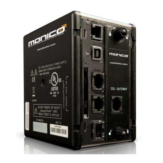
Page 13: Host Connections
Ethernet Port (RJ-45 Jack-Shielded). By default the Monico Gateway supports Modbus TCP Slave, BACnet UDPIP Slave, & SNMP over Ethernet. The Monico Gateway is fully capable of providing data via hundreds of other protocols and/or serially as an option. The above mentioned protocols can be established at either 10 BASE-T or 100 BASE-TX. -
Page 14: Monicoview Ii™ Programmer
OPENING a valid file or <EXTRACT>, it will result in a blank file being downloaded to the Gateway which will render it ineffective. If this should occur, contact Monico and we can send a copy of the file supplied with the Gateway. Please make note the Version Number on the label on the right side of the Gateway, so we can identify the appropriate file. -
Page 15: Usb Driver Troubleshooting
Figure 7 Click “Finish” when this screen is done. There is another driver that will need to be loaded, but it will not be found until you download the program to the Gateway. Note that after the initial installation or update of the Gateway program, Microsoft will find new hardware again and you will go through the same process again, but instead of calling it “G3 Loader”, it will be called “G3 HMI”. -
Page 16: Window Layout
Contact Monico Tech Support should this not resolve the problem. Window Layout To run MonicoView II, select the MonicoView II icon in the Monico section of your Start Menu. After a couple of seconds, MonicoView II will appear. The main MonicoView II window is comprised of three different panes as shown in Figure 9 below…... -
Page 17: Obtaining/Updating The Gateway Configuration
Figure 9 Obtaining/Updating the Gateway Configuration Before editing or making any changes to the Gateway, you must obtain the current configuration which resides in the Gateway. To do this: Connect the computer to the Gateway via the USB cable and make sure that the Gateway is powered. -
Page 18: Enabling Tcp/Ip Download
V1.03 15.4.29 Figure 10 Enabling TCP/IP Download Any function accomplished through the USB port can ALSO be performed over Ethernet however; you must ensure that a Compact Flash is installed whenever Firmware Updates are performed. A Firmware Update occurs whenever the unit is updated with a newer version of MonicoView II software than what it was originally programmed with. -
Page 19: Securing The Configuration (Optional)
By default, the Monico Gateway has three serial ports including two RS-232 ports and an RS-485 port. Monico View II can be used to configure and/or adjust the communication settings for any of the serial ports. For example, Figure 12 shows the default Modbus RTU Master Communication settings when interfacing to a Modlon Gateway as 38400, 8, N, 1. -
Page 20: Enable/Disbale Devices
MonicoView II supports “Live Data” viewing within a “Watch Window” that allows you to see the actual data acquired by the Monico Gateway in real time. This is a great trouble-shooting aid in determining what values are being acquired by the Gateway. Note that you must first be connected to the Gateway via USB or Ethernet in order to utilize this function. - Page 21 MonicoView II will ensure that the current configuration matches that of the Monico target device, and then will begin showing live data according to the appropriate format of the object. If the Gateway is successful in acquiring the data from the end device, it will show the value in real-time. If the Gateway is NOT able to acquire the data from the end device, it will show “n/a”...
-
Page 22: Configuration And Setup Of The Gateway Plus
Note: The following features are available on Monico Gateway Plus (GT) Models ONLY. The Web Server The Monico Gateway’s web server can be used to expose various data via TCP/IP connections. This allows remote access to the unit’s virtual HMI for remote monitoring and/or notifications. The web server is configured by selecting the Web Server category in the Navigation Pane. -
Page 23: Using The Security System
6.1.1.1 Setting Properties The Enable Web Server property is used to enable or disable the web server. By default, this property is enabled and the Gateway will wait for incoming requests and then fulfill the requests as required. If the server is disabled, connections to this port will be refused. Remember that in order for the server to operate;... - Page 24 V1.03 15.4.29 MonicoView II supports the ability to create any number of users, each of whom will have a username, a real name and a password. The username is a case-insensitive string with no embedded spaces that is used to identify the user when logging on, while the real name is typically a longer string that is used within log files to record the human-readable identity of the user making a change.
-
Page 25: Using Services
6.1.3 Using Services In addition to the core functions described earlier in this document, the Communications category also allows various services to be configured. These services appear in the Navigation Pane under the Services icon, and each is described below. 6.1.3.1 Using Time Management MonicoView II contains facilities to allow you to synchronize the time and date within the target device with a variety of sources. - Page 26 V1.03 15.4.29 Time Client Selecting “Yes” in the Enable SNTP property of the Time Client section will instruct MonicoView II to run its SNTP client. MonicoView II will then attempt to synchronize its clock with another MonicoView II-based device, or to another network-accessible SNTP time source such as a computer running Windows. The time client has the following additional properties…...
-
Page 27: Using Electronic Mail
unit. The alternative method is to use the system variables “TimeZone” and “UseDST”. The former holds the number of hours by which the local time zone differs from UTC, and may be either negative or positive. For example, a setting of –5 corresponds to Eastern Standard Time in the United States. The latter contains either 0 or 1, depending on whether Daylight Savings Time is active. - Page 28 V1.03 15.4.29 6.1.4.1 Adding Contacts The Contacts button can be used to access MonicoView II’s address book… Figure 20 Each entry allows a Display Name and an Address to be entered. The address should be in a format suitable for the required transport. For example, SMTP names should be in the usual format, while name@domain SMS names should be entered as international-format telephone numbers without the leading plus sign.
- Page 29 6.1.4.2 Configuring SMTP The SMTP tab is used to configure the Simple Mail Transport Protocol. This is the standard protocol used to send email over the Internet or over other TCP/IP networks. SMTP addresses follow the familiar standard. The configuration options for the SMTP transport are shown below: name@domain Figure 21 SMTP TRANSPORT...
- Page 30 V1.03 15.4.29 The Server Port Number property defines the TCP port number that will be used for SMTP sessions. The default value is 25. This value will be suitable for most applications, and will only need to be adjusted if the SMTP server has been reconfigured to use another port. ...
- Page 31 6.1.4.3 Configuring Alarm [Email] Notifications Alarm Notifications for EMAIL and/or SMTP Mail Recipients are setup through a data flag’s “Alarms Properties”. Individual data flags are accessed by selecting “Data Tags” at the bottom of the Navigation Pane. An example of setting up notification for “Genset Running” is shown in Figure 22. In this example there are 2 email notifications setup to indicate when the Genset is running and when it has stopped.
-
Page 32: Accessing The Virtual Hmi
Access to the Virtual HMI can be acquired through an internet browser by entering in the following url http://<IPaddress> , where “<IP Address>” is the Monico Gateway’s specified address on the network. When accessed, the following page will be displayed: Figure 23 Click on “Remote View”... - Page 33 Figure 24 - 33 -...
-
Page 34: Appendix A - Gateway Serial Ports
V1.03 15.4.29 7 APPENDIX A – Gateway Serial Ports RS-232 Connections RS-485/RS-422 Connections RS-485/RS-422 Schematic Please note that different companies use different terminology. For example, some use TxA and TxB to describe 2- wire RS-485 connections. Some use Tx+ and Tx-. In general. TxA=Tx- and TxB=Tx+. For 2-wire RS-485, use Pin#7 = (+) and Pin#8 = (-). -
Page 35: Appendix B - Specifications
8 Appendix B - SPECIFICATIONS POWER: 24 VDC ± 10% 200 mA min., without expansion card 1 Amp maximum with expansion card fitted Must use Class 2 or SELV rated power supply. COMMUNICATIONS: USB/PG Port: Adheres to USB specification 1.1. Device only using Type B connection. ...
Need help?
Do you have a question about the CDL Gateway and is the answer not in the manual?
Questions and answers