TREND T10 Original Instructions Manual
Router
Hide thumbs
Also See for T10:
- Original instructions manual (34 pages) ,
- Original instructions manual (32 pages)

Related Manuals for TREND T10


Summary of Contents for TREND T10
- Page 1 T10 & T11 ORIGINAL INSTRUCTIONS Please read these instructions before use. Failure to follow the warnings and instructions may result in electric shock, fire and/or serious injury.
-
Page 2: Table Of Contents
T10 & T11 Dear Customer Definitions: Safety Guidelines Thank you for purchasing this Trend product, The definitions below describe the level of we hope you enjoy many years of creative and severity for each signal word. Please read the productive use. -
Page 3: Technical Data
T10 & T11 WARNING: The declared vibration emission level ROUTER represents the main application of the tool. However T10E & T11E if the tool is used for different applications, with TECHNICAL DATA different accessories or poorly maintained, the vibration emission may differ. This may significantly Voltage UK &... -
Page 4: Safety
T10 & T11 SAFETY Keep cord from heat, oil and sharp 5. Consider working environment. Do edges. Always trail the power cord not use the product in the rain or in WARNING: away from the work area. a damp environment. Keep work area well lit. -
Page 5: Safety
Recommended speeds ensure there is sufficient clearance spanner or key and to the torque are shown in the Trend Routing between cutter tip and inside edge value provided by the manufacturer. Catalogue and/or website. -
Page 6: Electrical Safety
For 115V units with a power rating exceeding 1500W we recommend to use a plug to BS4343 Power Supply standard. For T10 & T11 this must be rated to 32A. The electric motor has been designed for one voltage only. Always check that the power supply corresponds to the voltage on the rating plate. -
Page 7: Ec Declaration Of Conformity
Always use cutters suitable for a speed of 2014/30/EU and 2011/65/EU. 30,000 min and marked accordingly. For more information please contact Trend at the n Never use cutters with a diameter exceeding following address or refer to back of manual. -
Page 8: Items Enclosed
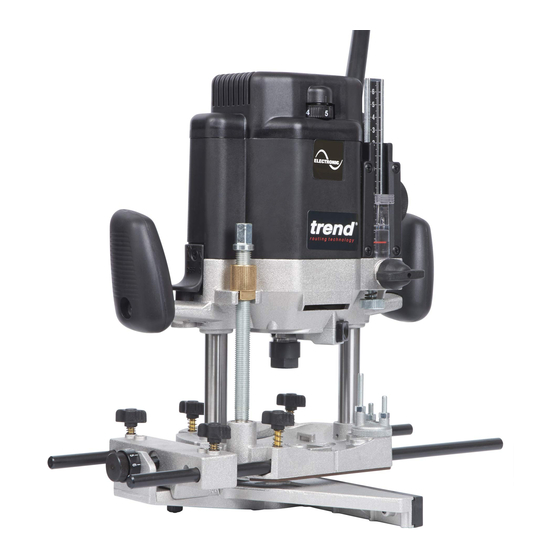
Check for damage to the tool, parts or accessories which may have occurred during transport. n Take the time to thoroughly read and understand this manual prior to operation. DESCRIPTION OF PARTS T10 Plunge locking lever Variable speed control dial Handle Template guide bush dia. 30mm... - Page 9 T10 & T11 DESCRIPTION OF PARTS T11 Plunge locking lever Variable speed control dial Handle Switch Depth stop locking knob Depth stop micro adjuster Depth stop height adjuster dial Depth stop scale Depth stop lens Thumb knob with anti-vibration spring...
-
Page 10: Assembly & Adjustment
T10 & T11 n Read the depth of cut using the measuring ASSEMBLY & ADJUSTMENT lens (5) and scale. n Adjust the depth of cut to the millimetre using Switching On & Off the knob (6). n On; pull the switch up. -
Page 11: Fitting & Removing Cutters
T10 & T11 How to Fit and Remove a Router Cutter Fitting Cutters n Insert at least of the shank length of the cutter (1) into the collet. n Press the spindle lock (2) forward until the router spindle is locked (you may need to turn the spindle slightly to engage it). -
Page 12: Speed Control
Dial Router Using a Fine Height Adjuster Speed The T10 has an optional fine height adjuster 8,000 rpm accessory Ref. FHA/003 and the T11 has a 12,000 rpm built in fine height adjuster called the Quick 16,000 rpm Raiser. -
Page 13: T10
NOTICE: Top clip (5) cannot be used with vacuum extractor hoses with a permanent adapter fitted. Fitting the T10 Fine Height Adjuster Optional Accessory Ref. FHA/003 n Plunge router and lock lever (6) down. n Remove hex cap (5) nut from threaded stud (3), using a 19mm A/F spanner. -
Page 14: Template Guide Bush
Turn the router upside down. n Fit inner plate (2) into the recess in the router base plate (1). For T10 the bushes on the inner plate must be towards the router motor. For T11 the raised side of the inner plate must be away from router base. -
Page 15: T11
Fitting Dust Extractor Spout Fitting and Removing T11 Dust Extractor Spout The dust extraction spout consists of a main section (1) with underside clip (7), an insert cover (2) and top clip (5) with screw (6). n Check underside clip (7) is fitted into main section. -
Page 16: Fine Height Adjuster
Fitting the T11 Fine Height Adjuster The fine height adjuster (Quick Raiser) for the Portable Use T11 can be used portably or when the router is held inverted in a table. If a suitable size access hole is drilled into the router table top, the height adjustment can also be adjusted from above the table top. -
Page 17: Accessories
Modification of User Router Table for T11 Fine Height Adjuster To use fine height adjuster in table mode a 20mm diameter hole is required to be drilled into the router table top. To position the hole it is advisable to remove the phenolic base slider of the T11 router and use it as a template. -
Page 18: Operation
T10 & T11 OPERATION Feed Speed WARNING: To reduce the risk of The speed at which the cutter is fed into the serious personal injury, always wood must not be too fast that the motor slows use proper hand position as down, or too slow that the cutter leaves burn shown. -
Page 19: Side-Fence Routing
T10 & T11 Side-Fence Routing The side-fence is used to guide the router when moulding, edge profiling or rebating the edge of the workpiece or when routing grooves and slots in the centre of the workpiece, parallel to the edge. -
Page 20: Template Guide Bush Routing
T10 & T11 Routing with a Template The guide bush is used in conjunction with a template when the routing operation is repetitive or the workpiece is complex in shape. The template is fixed to the upper surface of the workpiece. -
Page 21: Beam Trammel Routing Accessory
T10 & T11 Beam Trammel Routing Optional Accessory Ref. BEAM/002 Cutting Arcs with the Router n Fit the beam trammel (1) to the router base (3). n Place the machine on the workpiece and ensure pin on beam trammel will pierce the workpiece surface. -
Page 22: Bearing Guided Cutters
T10 & T11 Bearing Guided Cutter Routing Edge profiling and shaping cutters are available with a bearing fitted to the end. This enables shaped or straight workpieces to be routed without the need for a guiding device such as a side-fence or batten. -
Page 23: Freehand Routing & Batten Routing
Standard technique is used, Since accessories other than those offer and side pressure applied to by Trend, have not been tested with this ensure the router does not product, use of such accessories with this wander from the Clamp Guide. -
Page 24: Maintenance
Please call Trend Customer Services for advice as to how to dispose of unwanted Trend n Undo the two screws and take off the top electrical products in an environmentally safe cover. -
Page 25: Spare Parts - Spare Parts List
Carbon Brush 240V (1 pair) T10E & T11E >10/09 WP-T10E/004A 2 Core Cable Only 115V UK T10L & T11L WP-T10L/005 2 Core Cable with Plug 230V UK T10 & T11 WP-T10/005 2 Core Cable with Plug 230V Euro T10&T11/EURO WP-T10EUR/005 Brush Holder <10/09... - Page 26 T10 & T11 T10 & T11 - SPARE PARTS LIST v5.0 04/2015 Qty. Desc. Ref. Depth Stop Support (Left Hand) WP-T10/026 Depth Stop Support (Right Hand) WP-T10/027 Depth Stop Lens WP-T10/028 Screw Self Tapping Dome 3.8mm x 14mm PH WP-T10/029...
- Page 27 Speed Control Board 230V T10E &T11 WP-T10E/103 Washer Split Spring M4 WP-T10/104 Lead Switch to Speed Control (Red x 110mm F-F) WP-T10/105 Lead Switch to Speed Control (Red x 105mm M/F-F) WP-T10/106 Dust Spout T10 WP-T10/107 Dust Spout T11 WP-T11/107 Dust Spout Clip...
-
Page 28: Spare Parts List
T10 & T11 T10 & T11 - SPARE PARTS LIST v5.0 04/2015 Qty. Desc. Ref. Armature Kit 115V <10/09 T10EL & T11EL WP-T10EL/AK Armature Kit 230V <10/09 T10E & T11E WP-T10E/AK Manual T10 & T11 MANU/T10 Inner Plate T10 WP-T10/075... -
Page 29: Spare Parts Diagram
T10 & T11 T10 & T11 - SPARE PARTS DIAGRAM v5.0 04/2015 Please use only Trend original spare parts. IN AL OR IG IO NS RU CT IN ST Armature Kit - post Oct 2009 Nos. 1, 2, 3, 4, 6, 89... - Page 30 T10 & T11 T11 Fine Height Adjuster Fitting Hole Position 36mm Actual Size Ø 20mm 68mm Check this scale to a rule to ensure actual size, before use as a drilling template. Actual Size -28-...
- Page 32 RECYCLABLE © Copyright Trend 2013, 2015, 2017. No part of this publication may be reproduced, stored or transmitted in any form without prior permission. Our policy of continuous improvement means that specifications may change without notice. Trend Machinery and Cutting Tools cannot be held liable for any material rendered unusable or any form of consequential loss.
Need help?
Do you have a question about the T10 and is the answer not in the manual?
Questions and answers