Table of Contents
Advertisement
Quick Links
Advertisement
Table of Contents

Related Manuals for TREND KWJ900


Summary of Contents for TREND KWJ900
- Page 1 KWJ900...
-
Page 2: Table Of Contents
KWJ900 Dear Customer Thank you for purchasing this Trend product, we TECHNICAL DATA hope you enjoy many years of creative and Jig thickness 12mm productive use. Cutter size 12.7mm Please remember to return your guarantee card Workpiece thickness max. 45mm within 28 days of purchase. -
Page 3: Safety
KWJ900 SAFETY and balance at all times. Do not use recommended when working awkward or uncomfortable hand outdoors. Wear protective hair WARNING: positions. covering to contain long hair. Observe the safety regulations in the 17. Don’t abuse the cable. Never carry 5. -
Page 4: Safety
15. All fastening screws and nuts should be adhered to. Recommended speeds ensure there is sufficient clearance be tightened using the appropriate are shown in the Trend Routing between cutter tip and inside edge of spanner or key and to the torque Catalogue and/or website. -
Page 5: Items Enclosed
KWJ900 ITEMS ENCLOSED ITEMS REQUIRED s 1/2” plunge router. s Hand tools. s 30mm guide bush. s Panel connector bolts. s 12.7mm diameter x 50mm cut s Wooden biscuits Size No.20. router cutter with 1/2” shank. s Sealant. s 2 x trestles. -
Page 6: Accessories Recommended Cutters
KWJ900 C153, C153D, TR17, TR17D, 3/83, 3/83D ACCESSORIES Recommended Cutters Ref. 3/83X1/2TC, 3/83DX1/2TC, TR17, TR17D, C153X1/2TC, C153DX1/2TC or RT/13X1/2TC RT/13 A 12.7mm ( ”) diameter cutter must be used, which has a 50mm cutting reach and plunge cut facility. Description Order Ref. -
Page 7: Panel Connectors Bolts
KWJ900 Panel Connector Bolts Ref. PC/10/M ( Pack of 10) Ref. PC/50/M ( Pack of 50) Ref. PC/100/M ( Pack of 100) Ref. PC/1000/M ( Pack of 1000) Panel butt connectors are essential for connecting worktops. They fit into the recess on the underside of the worktop and are tightened with a 10mm spanner. -
Page 8: Assembly
KWJ900 ASSEMBLY Margin Distance Location Pin Identification Allow 8.5mm when cutting joints. Measure or Four location pins are used in different holes in the jig to align the correct template aperture for use a batten of this the application. thickness to aid setting out. -
Page 9: Cutting To Size
KWJ900 CUTTING TO SIZE 90° Joints PENCIL MARK PENCIL MARK POSTFORMED EDGE 45° Joints CUT OFF AREA 600mm Note: This dimension is based on a 600mm wide worktop... -
Page 10: Operation
KWJ900 OPERATION 90° JOINT - RIGHT HAND Setting Up for Right Hand 90° Female Joint s Place worktop face up and postformed edge towards you. s Place three pins in the holes marked F90. WORKTOP FACE UP s Place the fourth pin the hole marked 400, 450, 500, etc. - Page 11 KWJ900 Setting Up for Right Hand 90° Male Joint s Place worktop face down and postformed edge towards you. s Place two pins in the holes marked WORKTOP FACE DOWN M90. s Position the jig making sure both pins are pushed firmly against the worktop edge.
-
Page 12: Joint Left Hand
KWJ900 90° JOINT - LEFT HAND Setting Up for Left Hand 90° Female Joint s Place worktop face down and postformed edge towards you. s Place three pins in the holes marked F90. s Place the fourth pin the hole marked WORKTOP FACE DOWN 400, 450, 500, etc. - Page 13 KWJ900 Setting Up for Left Hand 90° Male Joint s Place worktop face up and postformed edge towards you. s Place two pins in the holes marked M90. WORKTOP FACE UP s Position the jig making sure both pins are pushed firmly against the worktop edge.
-
Page 14: Joint Right Hand
KWJ900 45° JOINT - RIGHT HAND Setting Up for Right Hand 45° Female Joint s Place worktop face up and postformed edge as shown. s Place two pins in the holes WORKTOP FACE UP marked F45. s Position the jig making sure the... - Page 15 KWJ900 Setting Up for Right Hand 45° Male Joint s Place worktop face down and postformed edge towards you. s Place two pins in the holes marked M45. s Position the jig as shown making sure WORKTOP FACE DOWN both pins are pushed firmly against the worktop edge.
-
Page 16: Joint Left Hand
KWJ900 45° JOINT - LEFT HAND Setting Up for Left Hand 45° Female Joint s Place worktop face down and postformed edge towards you. s Place two pins in the holes marked F45. WORKTOP FACE DOWN s Position the jig making sure the... - Page 17 KWJ900 Setting Up for Left Hand 45° Male Joint s Place worktop face up and postformed edge towards you. s Place two pins in the holes marked M45. s Position the jig making sure both pins are WORKTOP FACE UP pushed firmly against the worktop edge.
-
Page 18: Strengthening & Sealing The Joint
KWJ900 Strengthening the Joint If the joint between the worktops is not supported underneath, after some time the joint may ‘sag’ and become misaligned; to reduce this the joint should be reinforced with a loose tongue or biscuit dowels. The biscuit jointing cutter set Ref. -
Page 19: Corner Radius
KWJ900 Routing the Corner Radius Corner Radius R40mm or R100mm Special Note: Due to the nature of this particular cut, the corner radius will be more awkward to edge laminate. Locate the template on the worktop and line up by eye, ensuring the jig is laid at least 8mm in from the edges of the worktop to allow for the cutter and guide bush offset. -
Page 20: Square End Routing Of Worktops
KWJ900 Square End Routing of Worktops The jig can be used to square cut the worktop using the central slot. Engraved lines on the jig correspond to the edge of the worktop. Up to 650mm wide worktops can be square cut using the central slot as a router guide. -
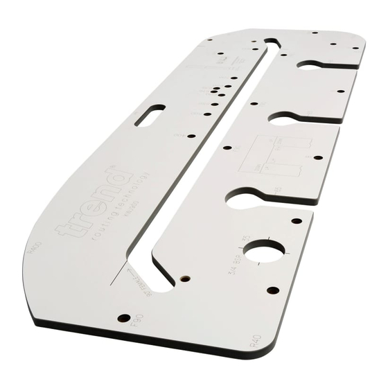
Page 21: Spare Parts - Spare Parts Diagram & List
KWJ900 KWJ900 - SPARE PARTS DIAGRAM v1.0 03/2005 KWJ900 - SPARE PARTS LIST v1.0 03/2005 Qty. Desc. Ref. KWJ900 KWJ900 Pin 10mm plastic (pack of 4) KWJ/PIN/4 Manual MANU/KWJ900 -20-... -
Page 22: Troubleshooting
KWJ900 TROUBLE SHOOTING Fault Cause Remedy s Joint does not fit correctly Cutter or guide bush is the Check concentricity of cutter at the radius. incorrect diameter or location with guide bush. Cutter 12.7mm pins are not against diameter with 30mm diameter worktop edge. - Page 23 RECYCLABLE © Copyright Trend 2010. No part of this publication may be reproduced, stored or transmitted in any form without prior permission. Our policy of continuous improvement means that specifications may change without notice. Trend Machinery and Cutting Tools...
Need help?
Do you have a question about the KWJ900 and is the answer not in the manual?
Questions and answers