Epson Stylus 1500 Service Manual
Hide thumbs
Also See for Stylus 1500:
- Service manual (181 pages) ,
- Reference manual (119 pages) ,
- Software manual (65 pages)
Table of Contents
Advertisement
Quick Links
Advertisement
Chapters
Table of Contents
Troubleshooting

Related Manuals for Epson Stylus 1500


Summary of Contents for Epson Stylus 1500
-
Page 1: Service Manual
EPSON ® Service Manual Stylus 1500 EPSON AMERICA, INC. TM-STYLUS15... - Page 2 EPSON Stylus 1500 Service Manual Revision Date 1st Printing 1/25/96...
- Page 3 EPSON Stylus 1500 Service Manual...
- Page 4 Neither Epson America, Inc., nor its affiliates shall be liable to the purchaser of this product or third parties for damages, losses, costs, or expenses incurred by purchaser or third parties as a result of: accident, misuse, or abuse of this product or unauthorized modifications, repairs, or alterations to this product.
- Page 5 Make certain that the source voltage is the same as the rated voltage listed on the serial number/rating plate. If the EPSON product has a primary AC rating different from the available power source, do not connect it to the power source.
- Page 6 Tel: (582) 241-0433 Fax: (562) 233-3197 Fax: (582) 241-6515 Epson Costa Rica, S.A. Epson Canada Limited San Jose, Costa Rica Willowdale, Ontario, Canada Tel: (506) 234-6666 (800) 922-8911 Fax: (506) 225-5709 Tel: (416) 498-9955 Fax: (416) 498-4574 EPSON Stylus 1500 Service Manual...
- Page 7 Free phone: 886-080-211172 Fax: 886-2-712-9164 Telex: 785-24444 Epson (U.K.) Ltd. Business Management Dept. (PC) Campus 100, Maylands Avenue Hemel Hempstead, Hertfordshire, HP2 7EZ, UK Phone: 44-442-227-355 Free phone: linkline 0800 289622 Fax: 44-422-227-427 Telex: 51-824767 EPSON Stylus 1500 Service Manual...
-
Page 8: Table Of Contents
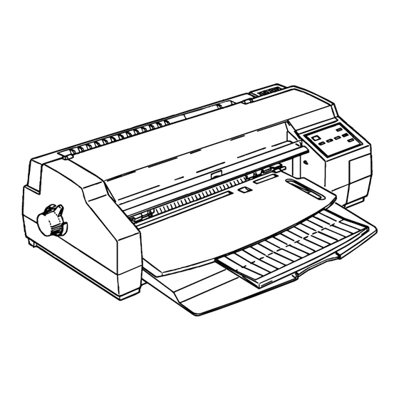
Power Supply Board..........1-34 EPSON Stylus 1500 Service Manual... - Page 9 Figure 1-1. Stylus 1500 Exterior View ....... . . 1-3...
-
Page 10: Printer Features
Printer Features The Stylus 1500 is a high-speed, high-quality color ink jet printer designed for business use. The main features of this printer are: High print quality for color graphics 720 dots per inch (dpi) printing High-speed 720 dpi printing... -
Page 11: Table 1-1. Options And Consumables
S020062 S020049 Color ink cartridge S041060 EPSON premium paper (360 dpi) Letter S041066 EPSON premium paper (360 dpi) Super A3 / B S041062 EPSON premium paper (720 dpi) Letter S041067 EPSON premium paper (720 dpi) Legal S041069 EPSON premium paper (720 dpi) Super A3 / B... -
Page 12: Specifications
Printer Features SPECIFICATIONS This section provides detailed information about the Stylus 1500. Printing Specifications Printing method: On-demand ink jet Nozzle configuration: Monochrome: 64 nozzles (32 x 2 staggered) Color: 60 nozzles (20 x 3, magenta, cyan, yellow) 1.129 mm 1.129 mm 1.129 mm... -
Page 13: Table 1-3. Character Tables And Fonts
EPSON Roman T 10.5 points, 8 - 32 points (in units of 2 points) EPSON Sans Serif H 10.5 points, 8 - 32 points (in units of 2 points) Note: Each typeface has four variations (normal, bold, italic, and bold italic). -
Page 14: Paper Feeding
Approximately 20 W (self-test with 10 cpi LQ characters) Insulation resistance: 10 MΩ minimum (500 VDC between AC line and chassis) Dielectric strength: 1000 VAC RMS for 1 minute or 1200 VAC RMS for 1 second between AC line and chassis EPSON Stylus 1500 Service Manual... -
Page 15: Environmental Conditions
CSA 22.2 950 with D3 EMC: FCC part 15 subpart B class B 220 - 240 V Version Safety standards: EN 60950 (TÜV, SEMKO, DEMKO, NEMKO, FIMKO) EMC: EN 55022 (CISPR Pub. 22) class B EN 50082-1 EPSON Stylus 1500 Service Manual... -
Page 16: Ce Marking
Printer Features CE Marking 220 - 240 V Version Lower Voltage Directive 73/23/EEC: EN60950 EMC Directive 89/336/EEC: EN55022 Class B EN50082-1 IEC801-2 IEC801-3 IEC801-4 Acoustic Noise Noise level: Approximately 45 dB (A) using ISO 7779 EPSON Stylus 1500 Service Manual... -
Page 17: Interfaces
Printer Features INTERFACES Hardware Interfaces This section describes Stylus 1500 interfaces. The printer is standard-equipped with a parallel interface. Parallel Interface Forward Channel Transmission mode: 8 bit parallel, IEEE-P1284 compatibility mode Synchronization: STROBE pulse Handshaking: BUSY and ACKNLG signal Signal level:... -
Page 18: Table 1-4. Connector Pin Assignments And Signals (Forward Channel)
— — Chassis ground. 16, 33 — — Signal ground. 19 - 30 15, 34 — — Not used. Note: The I/O column indicates the direction of the signal as viewed from the printer. EPSON Stylus 1500 Service Manual 1-11... - Page 19 The printer sends following device ID string when requested: ESC/P2 00H 36H MFG: EPSON; CMD: ESCPL2-00; MDL: Stylus 1500; CLS: PRINTER; XL24E 00H 37H MFG: EPSON; CMD: PRPXL24-00; MDL: Stylus 1500; CLS: PRINTER; Note: 00H denotes a hexadecimal value of zero. 1-12 EPSON Stylus 1500 Service Manual...
-
Page 20: Optional Interface
Not connected. Note: The I / O column indicates the direction of the signal as viewed from the printer. Optional Interface The Stylus 1500 supports an optional Type-B interface with the following characteristics: Reply Message: ESC/P2 is selected: Main type:... -
Page 21: Printer Language And Control Codes
Printer Features Printer Languages and Control Codes Printer languages and control codes: ESC/P2 IBM 24XL EPSON Remote 1-14 EPSON Stylus 1500 Service Manual... -
Page 22: Operations
Printer Features OPERATIONS This section describes the controls, settings, and adjustments used to operate the Stylus 1500. Control Panel The control panel for this printer is in the center of the upper case. The panel has 1 lock-type and 6 non-lock-type pushbuttons, and 10 LED indicators for easy operation of the various print functions. -
Page 23: Indicators
Lights when the printer is out of paper, and blinks when a paper jam occurs. Pause (orange) Lights when printing is paused. Economy (green) Lights when economy printing mode is selected. Condensed (green) Lights when condensed printing mode is selected. Font (green) Shows the selected font. 1-16 EPSON Stylus 1500 Service Manual... -
Page 24: Panel Functions At Power On
(for factory and service use only). Notes: 1. The + sign means to press one button while holding down the other button(s). 2. The EEPROM and Timer IC must be reset only by qualified service personnel. EPSON Stylus 1500 Service Manual 1-17... -
Page 25: Printer Conditions And Status
EEPROM and — On (for 1 second only) timer reset Fatal error — Blink — — — — — Blink — — Note: — means that the indicated printer status does not affect the LED. 1-18 EPSON Stylus 1500 Service Manual... -
Page 26: Default Settings
Figure 1-6. Default Setting Flowchart ATTENTION Any default value specified is not stored in the EEPROM until the printer is turned off. The last default value specified before power off is stored in the EEPROM. EPSON Stylus 1500 Service Manual 1-19... -
Page 27: Setting Menus
On / Off Auto tear off On / Off Plain paper (pure black) / Plain paper (composite black) / Print mode EPSON premium ink jet paper / Transparencies Paper roll On / Off Notes: *1. Refer to Tables 1-9 and 1-10. -
Page 28: Table 1-9. Print Direction Mode Characteristics
Bi-D Uni-D Uni-D Uni-D Auto (for DOS) Raster graphics mode Bi-D Uni-D Auto Bi-D Uni-D Bi-D Bi-D Uni-D Uni-D (for Windows) Note: The printing direction is controlled by a driver in the Windows environment. EPSON Stylus 1500 Service Manual 1-21... -
Page 29: Printer Adjustment Mode
Printer Features Printer Adjustment Mode The Stylus 1500 allows the user to adjust the printing direction and head gap without a special program. (Use continuous paper for all adjustment procedures.) The following list shows the adjustments for this printer in order:... - Page 30 No adjustment value specified is stored in the EEPROM until the printer is turned off. The last adjustment value specified before power off is stored in the EEPROM. Until all adjustments are executed, settings are not stored in the printer. Turn off the power to exit adjustment mode. EPSON Stylus 1500 Service Manual 1-23...
-
Page 31: Printer Initialization
To enter monochrome printing mode, turn the Power button off and back on again. Notes: 1. Once the printer has entered this function, print data must be re-sent. 2. The color select command (ESC r) is ignored. 1-24 EPSON Stylus 1500 Service Manual... -
Page 32: Paper Specifications
Thickness 0.003" (0.075 mm) - 0.0033" (0.085 mm) Notes: 1. Printing on transparencies is supported only at normal temperatures. 2. Use the designated side of the sheet to print on EPSON premium ink jet paper. Envelopes Table 1-13. Envelope Specifications No. -
Page 33: Table 1-15. Label (Cut Sheet) Specifications
The height from the base sheet to the label face is 0.0047" (0.12 mm) or less. label) Thickness 0.0047" (0.12 mm) (label) Quality Plain paper Note: Printing on continuous-paper labels is supported only at normal temperatures. 1-26 EPSON Stylus 1500 Service Manual... -
Page 34: Table 1-18. Banner Specifications
8.3" (210 mm) − 17" (432 mm) Width: Size Length: 196.6" (5 m) or less Thickness 0.0031" (0.08 mm) - 0.0039" (0.1 mm) Weight 17 lb (64 g/m ) - 22 lb (82 g/m Quality Plain paper EPSON Stylus 1500 Service Manual 1-27... -
Page 35: Printable Area
432 mm (25 mm) (25 mm) (62 mm) (62 mm) (3 mm) (14 mm) (17.0") Note: The printable area for labels on a cut sheet is the same as that for a regular cut sheet. 1-28 EPSON Stylus 1500 Service Manual... -
Page 36: Figure 1-9. Printable Area For Envelopes
Figure 1-9. Printable Area for Envelopes Table 1-20. Minimum Margins for Envelopes (Left Margin) (Right Margin) (Top Margin) (Bottom Margin) minimum minimum minimum minimum 0.12" 0.12" 0.12" 0.55" (3 mm) (3 mm) (3 mm) (14 mm) EPSON Stylus 1500 Service Manual 1-29... -
Page 37: Figure 1-10. Printable Area For Continuous Paper
Printable Area 1 M or e than 9 m m ( 0.35") Printable Area 2 Printable Area 1 More than 134 mm (5.28") Perforation More than 14 mm (0.55") Figure 1-10. Printable Area for Continuous Paper 1-30 EPSON Stylus 1500 Service Manual... -
Page 38: Adjust Lever Position
Table 1-21. Adjust Lever Position Platen Gap Paper Type Lever Position Adjustment Value Cut sheets, transparencies, Far side continuous paper, labels Envelopes, card stock Near side + 0.7 mm Figure 1-11. Adjust Lever Settings EPSON Stylus 1500 Service Manual 1-31... -
Page 39: Ink Cartridge Specifications
3. The ink freezes below 37 ° F (–3 ° C); however, it can be used after it returns to room temperature. PHYSICAL SPECIFICATIONS Weight: 25.4 lb (11 .5 kg) Dimensions: 26.1" (W) x 19.8" (D) x 8" (H) 664 mm (W) × 504 mm (D) × 202 mm (H) 1-32 EPSON Stylus 1500 Service Manual... -
Page 40: Main Components
Printer Features MAIN COMPONENTS The following are the main components of the Stylus 1500, designed for easy removal and repair: Main control board (C172 MAIN Board) Power supply board (C172 PSB/PSE Board) Control panel board (C172 PNL Board) Printer mechanism (M-4E60) -
Page 41: Power Supply Board
AC voltages (120 VAC and 220-240 VAC). The power switch is in the secondary circuit, allowing the CPU to remain active (20 seconds, minimum) after the printer is turned off. Regulator IC Fus e Transformer Diode Bridge Switching FET Figure 1-13. C172 PSB/PSE Board Component Layout 1-34 EPSON Stylus 1500 Service Manual... -
Page 42: List Of Figures
Color Printing ..........2-25 Normal Dot/EPSON Micro Dot Printing Modes ....2-26... - Page 43 Figure 2-29. Color Data Transmission Timing ......2-25 Figure 2-30. EPSON Micro Dot Printing Driver Waveform ....2-26 List of Tables Table 2-1.
-
Page 44: Printer Mechanism Operating Principles
This printer mechanism uses a drop-on-demand ink jet system similar to the one used on all other EPSON ink jet printers. However, the printhead in this system has been completely redesigned to make it more compact and to ensure a high level of reliability. The printer has two printheads: monochrome (black ink) and color (yellow, cyan, and magenta ink). - Page 45 Tc pulse. EPSON Micro Dot Printing Mode The Stylus 1500 has a special black ink printing mode called EPSON Micro Dot Printing Mode. This mode can be selected when using a special paper type (such as glossy or transparency).
-
Page 46: Printer Mechanism
Operating Principles Printer Mechanism The Stylus 1500 printer mechanism is composed of the printhead unit; paper feed, carriage drive, pump, and push tractor feed mechanisms; and various sensors. The figure below shows a functional block diagram of the printer mechanism. Depending on the position of the carriage unit, the paper feed motor torque is transmitted to the paper feed, auto sheet feed, push tractor feed, or pump mechanisms via a disengage mechanism. -
Page 47: Carriage Drive Mechanism
Operating Principles Carriage Drive Mechanism The timing belt attached to the base of the carriage unit is driven by the carriage motor, causing the carriage unit to move along the carriage guide shaft from left to right or vice versa. The carriage drive motor in this printer is a 4-phase, 96-pole, hybrid-type stepping motor, allowing the printer to stop the carriage or change the carriage movement at any position. -
Page 48: Paper Feed Mechanism
0.75 / 0.75 0.6 / 0.6 Pump drive — / 0.9 0.9 / — 0.75 / 0.75 Pump drive — / — — / — 0.75 / 0.75 (lower speed) Note: Hold current is 0.6 A. EPSON Stylus 1500 Service Manual... -
Page 49: Auto Sheet Feeder Mechanism
Operating Principles PF Motor Release Gear PF Motor Pinion Gear Disengage Gear To Tractor To A SF ASF Tra nsmission Ge ar PF Roller Paper Eject Roller Pu mp Un it Eject Roller Unit Eject Paper Shaft Figure 2-6. Paper Feed Mechanism Auto Sheet Feeder Mechanism The PF motor torque is transmitted to the ASF pickup rollers via a planetary gear in the disengage mechanism. -
Page 50: Push Tractor Mechanism
ASF. This mode therefore allows use of normal paper in the ASF and special paper (such as glossy or transparency paper recommended for single-sheet feeding) in the rear slot at the same time. EPSON Stylus 1500 Service Manual... -
Page 51: Platen Gap Adjust Mechanism
Operating Principles Platen Gap Adjust Mechanism Set the platen gap adjust lever, attached to the left upper side of the printer cover, to the appropriate position for the paper thickness. The platen gap adjust mechanism consists of the platen gap adjust lever, carriage guide shaft, and two parallelism adjust bushings. Switching the lever between positions 0 and + rotates the carriage guide shaft toward the front or rear. -
Page 52: Ink System
Color Ink Cartridge (Option) Head Cleaner PF Motor Clutch Unit Disengage Gear Air Valve Pu mp 1 Pu mp Un it Gear Train Pu mp 2 Waste Ink Drain Tank Figure 2-10. Ink System Block Diagram EPSON Stylus 1500 Service Manual 2-11... -
Page 53: Pump Mechanism
Operating Principles Pump Mechanism The paper feed motor drives the pump mechanism when the transmission gear moves to where the motor engages the pump mechanism gear trains (when the carriage unit is at the ink system home position). Release cam set engages (Figure 2-11) and disengages (Figure 2-13) the pump mechanism to switch to paper feed (Figure 2-14). - Page 54 Release Cam Lever Release Cam Figure 2-13. Release Cam Reset Carriage Unit PF Motor Pinion Gear PF Motor Switch Lever Disengage Gear Release Cam PF Roller Pump Unit Figure 2-14. Paper Feed Mechanism Function EPSON Stylus 1500 Service Manual 2-13...
- Page 55 Operating Principles Pump Operation The pump draws ink from the printhead nozzles and drains it into the waste ink drain tank to eliminate dust or bubbles in the nozzles. The figure below illustrates pump operation. When the paper feed drive motor rotates backward (counterclockwise), the color pulleys in the wheel pump unit rotate in the direction of the arrow while squeezing the ink tube to push the ink out to the waste ink drain tank.
-
Page 56: Cap Mechanism
Carriage Unit Carriage Unit Carriage Switch Lever Head Cleaner Printhead Head Cleaner Lever Head Cleaner Lever PF Motor Disengage Mechanism Gear Train Pump Gear / Clutch Wiping Mechanism Figure 2-17. Wiping Mechanism EPSON Stylus 1500 Service Manual 2-15... -
Page 57: Electrical Circuit Operating Principles
Operating Principles ELECTRICAL CIRCUIT OPERATING PRINCIPLES The Stylus 1500 contains the following circuit boards: C172 MAIN board (main control circuit board) C172 PSB/PSE board (power supply circuit board). This is the same board used in the Stylus Color printer. C172 PNL (control panel board) In addition to the circuit boards above, part of the printhead drive circuit is built on a separate circuit board installed in the carriage unit;... - Page 58 +42 VDC Line Overcurrent Protection Circuit The output current is monitored by transistors Q81 and Q82. This circuit feeds back output voltage level status through photocoupler PC1 to the primary switching circuit to stop circuit operation. EPSON Stylus 1500 Service Manual 2-17...
-
Page 59: Main Control Circuit Operating Principles
Operating Principles Main Control Circuit Operating Principles The main control circuit for this printer is the C172 MAIN board, which is controlled by a 16-bit TMP96C061AF CPU (IC1) running at 24.57 MHz. A 4M DRAM (CAS method) on this board is controlled by the CPU itself. -
Page 60: Reset Circuits
B H C O (CN13) +5 V +5 V Disengage Release Sensor Sensor P 7 6 RE L E A S E P 8 3 (CN14) (CN15) +5 V Figure 2-22. Sensor Circuit Block Diagram EPSON Stylus 1500 Service Manual 2-19... - Page 61 Operating Principles HP sensor A photocoupler-type home position (HP) sensor is attached to the surface of the printer mechanism to detect the carriage home position. A HIGH level signal from this sensor indicates the carriage is in the home position. Front PE A mechanical switch paper end (PE) sensor is built into the printer mechanism to sensor...
-
Page 62: Carriage Motor Driver Circuit
When the strobe pulse becomes active from the E05B16 (IC2) clock, serial data is moved into the reference voltage selection circuit and the voltage is changed. Therefore, when the printer is in constant-speed mode, this strobe pulse becomes inactive. EPSON Stylus 1500 Service Manual 2-21... -
Page 63: Paper Feed Motor Driver Circuit
Operating Principles Paper Feed Motor Driver Circuit The paper feed motor for this printer drives the following mechanisms: Paper feed Paper pickup Pump The UDN2917EB paper feed motor driver IC (IC15) outputs a constant current to drive the paper feed motor. The E05B12 gate array (IC2) determines the motor phase (PFAPH and PFBPH), phase current (PFA0/1 and PFB0/1), and current setting signals (PFV), and then sends the signals to the paper feed motor driver IC. -
Page 64: Printhead Driver Circuit
ICL K DO60 - 1 C H S O Cy a n IE N Yellow 41~44 ID1~ID4 CPSID1 ~4 DRIVER CIRCUIT ON CARRIAGE C17 2 MAIN BOARD Figure 2-26. Printhead Driver Circuit Block Diagram EPSON Stylus 1500 Service Manual 2-23... -
Page 65: Black Printing
Operating Principles Black Printing Common Driver Circuit The common voltage (VH) corresponds to characteristics of the specific black printhead installed. This value is stored in advance in the EEPROM on the C172 MAIN board by the host computer. (See Head Data Writing Operation in Chapter 4.) Gate array E05B16 (IC2) refers to this value when it outputs parallel data for voltage control signals (BHV0 - BHV5) to the common driver circuit. -
Page 66: Color Printing
After this, the nozzle selected by the head data is activated to eject the ink. CHSO # 6 4 CHCLK CHLAT C H 2 C CH2D1/0 Figure 2-29. Color Data Transmission Timing EPSON Stylus 1500 Service Manual 2-25... -
Page 67: Normal Dot/Epson Micro Dot Printing Modes
Normal Dot / EPSON Micro Dot Printing Modes The Stylus 1500 uses two ink eject modes (normal dot and EPSON Micro Dot) for monochrome ink printing. Normal dot printing mode uses a larger dot size than Micro Dot printing, so the space between dots is narrower. -
Page 68: Ink System Management
It is performed during continuous printing outside the printable area to increase throughput. False Absorbing This operation absorbs ink inside the cap and eliminates ink on the nozzle plate. Wiping This operation eliminates dust or ink from the nozzle plate using the head cleaner. EPSON Stylus 1500 Service Manual 2-27... -
Page 69: Counters
Operating Principles Rubbing This operation removes dust or ink that adheres to the head surface. It eliminates ink by ejection and absorption. Micro Absorbing When the cartridge is removed, it is possible for a small amount of air to form bubbles that can block the ink from the nozzles. - Page 70 Figure 3-16. Data Found on the Black Head ......3-19 EPSON Stylus 1500 Service Manual...
- Page 71 Table 3-1. Tools..........3-5 Table 3-2. Equipment Required for Maintenance ......3-5 EPSON Stylus 1500 Service Manual...
-
Page 72: Precautions For Disassembling The Printer
Risque d’explosion si la pile est remplacée incorrectement. Ne remplacer que par une pile du même type ou d’un type équivalent recommandé par le fabricant. Elminer les piles déchargées selon les lois et les règles de sécurité en vigueur. EPSON Stylus 1500 Service Manual... - Page 73 After you reassemble the printer, if the sliding cam is forward and the carriage lock is engaged, the carriage will bang into it on power up. To correct this problem if it occurs, push down the cam as shown, and on power up the printer will retract the lock. EPSON Stylus 1500 Service Manual...
-
Page 74: Tools
B741700200 Torque wrench B765106901 Commercially available EPSON-exclusive Table 3-2. Equipment Required for Maintenance Description Specification Multimeter — Oscilloscope 50 MHz Note : An oscilloscope is required only for servicers who repair to the component level. EPSON Stylus 1500 Service Manual... -
Page 75: Procedures For Disassembly And Assembly
Base Frame Removal Front /Rear PE Sensor Removal 3-27 Paper Eject Drive Unit Frame Removal 3-29 Paper Pickup Roller Unit Removal 3-31 Paper Feed Roller Unit Removal 3-32 Middle Frame Unit Removal Figure 3-1. Disassembly Flowchart EPSON Stylus 1500 Service Manual... -
Page 76: Upper Housing Assembly Removal
Then, disconnect the panel harness from the connector on the C172 MAIN board. Control Panel Panel Harness Tw eezers Upper Housing Figure 3-3. Removing the Control Panel EPSON Stylus 1500 Service Manual... - Page 77 Tractor Unit CBB 4x20 Printer Cover CBB 3x12 Release Lever K n o b Control Panel CBB 3x12 Upper Housing Lower Housing Hooks for Lower Housing Ink Cartridge Cover Figure 3-4. Removing the Upper Housing EPSON Stylus 1500 Service Manual...
-
Page 78: Printer Mechanism (M-4E60) Removal
H ole in the Ink C artridge H older C over C B 4 x 14 C B 4 x 14 P rinter M echanism Low er H ousing S haft for the Low er H ousing Figure 3-5. Removing the Printer Mechanism EPSON Stylus 1500 Service Manual... -
Page 79: Main Controller (C172 Main Board) Removal
The C172 MAIN board shield plate has sharp edges, so take care handling it. Take care handling the lithium battery, as described on page 3-3. Replace the control panel harness, and then remove the main controller . 3-10 EPSON Stylus 1500 Service Manual... - Page 80 C17 2 MAIN Boa rd C N 4 CP 3 x 6 CBP 3 x12 CBS 3 x 12 Upper Connector Cover L owe r Hou sin g Figure 3-6. Removing the C172 MAIN Board EPSON Stylus 1500 Service Manual 3-11...
-
Page 81: Power Supply Unit (172 Psb/Pse Board) Removal
Therefore, disconnect the power cable from the AC inlet. CBP 3 x 12 C172 PSB/PSE C N 2 C N 1 Lower Housing Figure 3-7. Removing the Power Supply Unit 3-12 EPSON Stylus 1500 Service Manual... -
Page 82: Cr Motor Removal
1 mm of the back of the fan and set the sink side of fan toward the outside. (See Chapter 6.) Less than 1 mm CR Moto r Ad he sive Point Sink side CR Motor Fan Figure 3-9. Applying Adhesive to the CR Motor Fan EPSON Stylus 1500 Service Manual 3-13... -
Page 83: Pf Motor Removal
CAUTION Never touch the white PF gears. Handling them will cause damage or contamination that will affect print quality. PF Motor Mid dle Frame Unit Hexagon Nut (M3) Figure 3-10. Removing the PF Motor 3-14 EPSON Stylus 1500 Service Manual... -
Page 84: Release Sensor Removal
Then pull the sensor off, as shown in the figure below.) HP Sensor Pap er Eject Frame HP Sensor Cable Tw eezers Figure 3-12. Removing the HP Sensor EPSON Stylus 1500 Service Manual 3-15... -
Page 85: De Sensor Removal
Then pull the sensor off, as shown in the figure below.) DE Sen sor Ca ble Sub Select Cam Frame Tweezers DE Sensor Hook for DE Sensor Figure 3-13. Removing the DE Sensor 3-16 EPSON Stylus 1500 Service Manual... -
Page 86: Black Head Removal
Ink Supply Tube O-ring Tube Cover CB(P2) 3 x 6 Head Damper CR Co ve r Head Fastening Pin Twe eze rs Head FFC Black Head Carriage Unit Figure 3-14. Removing the Black Head EPSON Stylus 1500 Service Manual 3-17... -
Page 87: Black Head Assembly
Plate Holding the Tube Tube Cover (Ink Supply Tube) FFC Holder Head FFC 3 2 ~ 3 4 mm FFC Holder B Left Frame Figure 3-15. Adjusting the Ink Supply Tube and Left Frame 3-18 EPSON Stylus 1500 Service Manual... - Page 88 Chapter 4. Nozzles Ran k of Ho lding Time 2 Normal Dot Drive Voltage Micro Dot Drive Voltage Serial Number Black Head Figure 3-16. Data Found on the Black Head EPSON Stylus 1500 Service Manual 3-19...
-
Page 89: Left / Right Ink Drain Pad Removal
Printer Mechanism Drain Pad Cover Left Drain Pad Paper Eject Drive Unit Lower Housing Figure 3-17. Removing the Ink Drain Pad 3-20 EPSON Stylus 1500 Service Manual... -
Page 90: Printer Mechanism (M-4E60) Disassembly
When you attach the ink supply tube, insert the nut used to fasten the tube first, and then insert O-ring into the ink supply tube. Tighten the screws using a torque wrench. The tightening torque for the nut is 0.09 ~ 0.11 Nm (0.90 ~ 1.1 kg-cm). EPSON Stylus 1500 Service Manual 3-21... -
Page 91: Carriage Unit Removal
Remove the CR guide shaft from the carriage unit. Figure 3-19. Removing the Carriage Unit REQUIRED ADJUSTMENTS See Table 4-1 for the complete list of adjustments required when the carriage unit is removed or disassembled. 3-22 EPSON Stylus 1500 Service Manual... - Page 92 When you attach the timing belt to the carriage unit, insert the timing belt with the teeth out from the carriage unit, as shown in the figure below. Timing Belt Carriage Unit Figure 3-20. Attaching the Timing Belt EPSON Stylus 1500 Service Manual 3-23...
-
Page 93: Paper Eject Frame Unit Removal
CBS 3 x 6 Paper Eject Frame Unit Left Frame Middle Frame Right Frame Figure 3-21. Removing the Paper Eject Frame Unit 3-24 EPSON Stylus 1500 Service Manual... -
Page 94: Pump Unit Removal
CBS 3 x 6 Rubber Face of Head Cleaner Head Cleaner Lever Pump Unit Middle Frame Right Frame CBP 3 x 8 Figure 3-22. Removing the Pump Unit EPSON Stylus 1500 Service Manual 3-25... -
Page 95: Base Frame Removal
Fr ame Cam Support CBS 3 x 6 Plain Washer Paper Feed Roller Unit Left Frame Tractor Release Cam Spur Gear (46 mm) Compression Spring (1.95 g) E-ring Figure 3-23. Removing the Base Frame 3-26 EPSON Stylus 1500 Service Manual... -
Page 96: Paper Eject Drive Unit Removal
Paper Feed Roller Unit CBP 3 x 8 Trigger Lever Pickup Roller Unit Ho p p er Asse mb ly Left Paper Eject Assembly Right Paper Eject Assembly Figure 3-24. Removing the Paper Eject Drive Unit EPSON Stylus 1500 Service Manual 3-27... - Page 97 Cam Cover Assembly Pickup Roller Unit Plain Washer Left Paper Eject Assembly Right Paper Eject Assembly Figure 3-25. Attaching the Left / Right Paper Eject Assemblies 3-28 EPSON Stylus 1500 Service Manual...
-
Page 98: Paper Pickup Roller Unit Removal
Figure 3-26. Removing the Paper Pickup Roller Unit CAUTION When disengaging the ASF transmission ratchet from the paper pickup roller unit, remove the ratchet to prevent it from hitting the spur gear (24 mm) as shown in the following figure. EPSON Stylus 1500 Service Manual 3-29... - Page 99 Spur Gear (29 mm) in the ASF Transmission Gear Set Pap er Pickup Ge ar Figure 3-27. Engaging the Gears CAUTION To preserve paper-feed accuracy, do not damage the surface of the gears, and do not touch them with your bare hands. 3-30 EPSON Stylus 1500 Service Manual...
-
Page 100: Paper Feed Roller Unit Removal
Spur Gear (33.6 mm) Spur Gear (24 mm) Bus hing Peper Feed Roller Unit Grounding Roller Spring A S F Transmission Ratchet E-ring Spur Gear (40 mm) Figure 3-28. Removing the Paper Feed Roller Unit EPSON Stylus 1500 Service Manual 3-31... -
Page 101: Middle Frame Unit Removal
Never touch the white PF gears. Handling them will cause damage or contamination that will affect print quality. Middle Frame Unit CBS 3 x 6 ASF Transmission Ratchet Paper Pickup Guide Frame Bottom Frame Figure 3-29. Removing the Middle Frame Unit 3-32 EPSON Stylus 1500 Service Manual... -
Page 102: Front / Rear Pe Sensor Removal
Rear Paper Guide Assembly Rear PE Sensor Cable Rear PE Sensor Cable Front PE Sensor Cable Hoo k s Front PE Sensor Cable Figure 3-30. Removing the Front / Rear PE Sensors EPSON Stylus 1500 Service Manual 3-33... -
Page 103: Rom Replacement
Remove the (CBP 3 × 6) screw securing the ROM cover to the lower housing, and then remove the cover. Replace the ROM. CAUTION When replacing the ROM, disconnect the AC cable from the AC inlet. 3-34 EPSON Stylus 1500 Service Manual... - Page 104 Table 4-3. Customer Data ......... . 4-7 EPSON Stylus 1500 Service Manual...
- Page 105 Adjustments EPSON Stylus 1500 Service Manual...
- Page 106 To correct this problem if it occurs, push down the cam as shown, and on power up the printer will retract the lock. Figure 4-1. Pushing the Sliding Cam EPSON Stylus 1500 Service Manual...
- Page 107 5. Black - color head vertical adjustment. (See page 4-22.) 6. Head gap adjustment. (See page 4-25.) After replacing or 1. Uni-D alignment adjustment. (See page 4-17.) disassembling the CR motor 2. Bi-D alignment adjustment. (See page 4-19.) Black head only EPSON Stylus 1500 Service Manual...
-
Page 108: Platen Gap (Pg) Adjustment
After adjusting the gap on the left side, perform the gap adjustment on the right side in the same way as for the left side. Repeat steps 1 to 5 for both sides of printer to create the correct platen gap. EPSON Stylus 1500 Service Manual... - Page 109 Is right PG OK? Set the PG adjust lever to +. Move the carriage unit to the left. Set the PG adjust lever to 0. Is left PG OK? Figure 4-3. Platen Gap Adjustment Flowchart EPSON Stylus 1500 Service Manual...
-
Page 110: Destination Data Writing Operation
(EAI) — — 20000A00 20000A00 00000A00 Northern Middle East 20010A00 Europe 20010A00 20010A00 — — (EUL) (EUL) CAUTION If you enter an incorrect ID number for the “Customer Data” field, printer functions are not guaranteed. EPSON Stylus 1500 Service Manual... - Page 111 Choose END by selecting it from the keyboard. Choose another selection if you want to continue in the adjustment mode. The following menu appears on the display. If you want end the program, press 5. Stylus 1500 <********> Customer Data <********> 95/**/** ( Customer Data Input ) ..1 ( Adjustment ) ..
-
Page 112: Head Data Writing Operation
Refer to the printhead circuit board to input the head data. (See Figure 3-16.) Nozzles Rank o f Holding Time 2 Normal Dot Drive Voltage Micro Dot Drive Voltage Serial Number Black Head Figure 4-4. Printhead Voltage Value EPSON Stylus 1500 Service Manual... - Page 113 The menu below appears on the display. If you want to end the program, press 5. Stylus 1500 <********> Customer Data <********> 95/**/** ( Customer Data Input ) ..1 ( Adjustment ) ..
-
Page 114: Black Head Angle Adjustment
Select:<Up> or <Down> Go:<SPACE> or <ENTER> Change menu:<1> or <2> Move the cursor to “Black Head Angle Adj.” to perform the black head angle adjustment operation by pressing the 1, 2, ↑, and ↓ keys. EPSON Stylus 1500 Service Manual 4-11... - Page 115 To ma in men u Figure 4-7. Black Head Angle Adjustment Flowchart Press ENTER to exit the setting mode, or press SPACE to continue entering settings. Fasten the 2 (CBP (P2) 3 × 6) screws. 4-12 EPSON Stylus 1500 Service Manual...
- Page 116 10. The menu below appears on the display. If you want end the program, press 5. Stylus 1500 <********> Customer Data <********> 95/**/** ( Customer Data Input ) ..1 ( Adjustment ) ..
-
Page 117: Color Head Angle Adjustment
Move the cursor to “Color Head Angle Adj.” to perform the color head angle adjustment operation by pressing 1, 2, ↑, and ↓. Patterns are printed out with the color (magenta, cyan and yellow) adjustment pattern. The color head angle adjustment pattern is shown in the following illustration. 4-14 EPSON Stylus 1500 Service Manual... - Page 118 1 step to the front. 1 step to the rear. Is the color head an g le O K? Pres s ENTER k ey . To main men u. Figure 4-10. Color Head Angle Adjustment Flowchart EPSON Stylus 1500 Service Manual 4-15...
- Page 119 10. The following menu appears on the display. If you want end the program, press 5. Stylus 1500 <********> Customer Data <********> 95/**/** ( Customer Data Input ) ..1 ( Adjustment ) ..
-
Page 120: Uni-D (Unidirectional Printing) Alignment Adjustment
Press SPACE and ENTER to enter the adjustment mode. The printer prints out an adjustment pattern, and the adjustment selection menu appears, as shown below. < Draft Uni-D > DATA : ** n Select: Cursor<Up> or <Down> Print:<SPACE> OK:<ENTER> Figure 4-11. Uni-D Adjustment Pattern EPSON Stylus 1500 Service Manual 4-17... - Page 121 The menu below appears on the display. If you want end the program, press 5. Stylus 1500 <********> Customer Data <********> 95/**/** ( Customer Data Input ) ..1 ( Adjustment ) ..
-
Page 122: Bi-D (Bidirectional Printing) Alignment Adjustment
..ENTER Choose the number for printer speed you are using for the adjustment. If you choose 1, the Bi-D adjustment pattern is printed out at 400 cps, as shown in the next illustration. EPSON Stylus 1500 Service Manual 4-19... - Page 123 Print Bi-D pattern. Is Bi-D OK ? Misalignment direction ? Press ENTER key. Press down arrow Press up arrow key. key. All speed OK? Press ENTER key. To main menu Figure 4-13. Bi-D Adjustment Flowchart 4-20 EPSON Stylus 1500 Service Manual...
- Page 124 The menu below appears on the display. If you want end the program, press 5. Stylus 1500 <********> Customer Data <********> 95/**/** ( Customer Data Input ) ..1 ( Adjustment ) ..
-
Page 125: Black - Color Head Vertical Adjustment
Move the cursor to “Black-Color HV Adj.” to perform the Black - Color Head vertical adjustment operation by pressing 1, 2, ↑, and ↓. Press SPACE and ENTER to enter the adjustment mode. The adjustment selection menu appears, and the adjustment patterns are printed as follows: 4-22 EPSON Stylus 1500 Service Manual... - Page 126 0 to 6. Input the value of the nearest pattern ( 0 ~ 6). Print the selected pattern. Is the adjustment OK ? Press the ENTER key. Figure 4-16. Black - Color Head Vertical Adjustment Flowchart EPSON Stylus 1500 Service Manual 4-23...
- Page 127 The menu below appears on the display. If you want end the program, press 5. Stylus 1500 <********> Customer Data <********> 95/**/** ( Customer Data Input ) ..1 ( Adjustment ) ..
-
Page 128: Head Gap Adjustment (Black And Color Head)
Adjustment Mode ..2 ..ENTER SELECT No. Enter 1 or 2 to select the print resolution. Then the printer outputs an adjustment pattern, as shown below. Black Magenta Black Figure 4-17. Head Gap Adjustment Pattern EPSON Stylus 1500 Service Manual 4-25... - Page 129 Reset protect counter B using the adjustment program to make the printer perform the initial ink charge operation before sending the unit back to the customer. The menu below appears on the display. To end the program, press 5. Stylus 1500 <********> Customer Data <********> 95/**/** ( Customer Data Input ) ..1 ( Adjustment ) ..
-
Page 130: Initial Ink Charge Function
Move the cursor to “END” by pressing 1, 2, ↑, and ↓, and then press ENTER to exit the adjustment program. Turn off the printer. CAUTION After you reset protect counter B, no one but the customer should turn on the printer. EPSON Stylus 1500 Service Manual 4-27... - Page 131 Table 5-7. Repair of the Printer Mechanism......5-14 EPSON Stylus 1500 Service Manual...
- Page 132 Troubleshooting EPSON Stylus 1500 Service Manual...
-
Page 133: Troubleshooting
Sensor Change the pulse width of the charge pulse for the common driver circuit. TH Sensor Pin 13 to Pin Analog data Themistor resistance: Approx.10K Ω 16, 18, or 20 (at 25° C, 77° F) EPSON Stylus 1500 Service Manual... - Page 134 Blinks — — — — — — Blinks — — printer and turn it Fatal Error on again. Note: — means this light’s status is not used to indicate the message in the left column. EPSON Stylus 1500 Service Manual...
-
Page 135: Unit Level Troubleshooting
Abnormal printing (missing dots, etc.) Print quality is poor No paper is fed. Printer does not feed the paper Paper feed is irregular. correctly Paper jam occurs. Control panel operation is No response to button access. abnormal EPSON Stylus 1500 Service Manual... -
Page 136: Printer Does Not Operate At Power On
Replace any bad parts. (If a motor and driver are bad, replace both at the same time.) Is the problem corrected ? Replace the main board. Figure 5-1. Flowchart — 1 EPSON Stylus 1500 Service Manual... -
Page 137: Error Is Detected
Replace the waste ink absorbing material, and reset the protect counter. (See page 3-20 .) Check release and ink cartridge sensor and, if bad, replace. Fgiure 5-2. Flowchart — 2 EPSON Stylus 1500 Service Manual... -
Page 138: Failure Occurs During Printing
OK, replace the main board. Is the problem corrected ? Y E S Check all motors, drivers, and printhead E ND for shorts. If they are OK, replace the main board. Fgiure 5-3. Flowchart — 3 EPSON Stylus 1500 Service Manual... -
Page 139: Printer Does Not Feed The Paper Correctly
Is the problem corrected ? Clean the paper feed rollers and path Is the problem corrected ? See the section describing repair of the printer mechanism. Fgiure 5-4. Flowchart — 4 EPSON Stylus 1500 Service Manual... -
Page 140: Control Panel Operation Is Abnormal
Is the control panel connected properly ? Connect the control panel correctly. Is the problem corrected ? Replace the control panel. Is the problem corrected ? Replace the main board. Fgiure 5-5. Flowchart — 5 5-10 EPSON Stylus 1500 Service Manual... -
Page 141: Unit Repair - C172 Psb/Pse Board
. Repla ce PC1. Check the pin 5 waveform of L4962. Replace L4962. +5 V line is Regulator de ad . IC L4962 is dead. Check the pin 7 waveform of L4962. Replace L4962. EPSON Stylus 1500 Service Manual 5-11... -
Page 142: Unit Repair - C172 Main Board
Check the waveforms of IC15 pin 6 or 17. Replace IC2. The carriage The carriage IC2 is defective. motor does does not operate not operate normally. normally. Replace CPU is defective. IC2 or MAIN. board 5-12 EPSON Stylus 1500 Service Manual... - Page 143 Paper feed board. does not operate normally. PF motor does not rotate. Check the signals from pins 3, 6, or pins 18, 21 of IC16. IC15 is defective. Replace IC16 or MA IN borad. EPSON Stylus 1500 Service Manual 5-13...
-
Page 144: Unit Repair - Printer Mechanism (M-4E60)
The carriage Measure the coil Replace the motor is defective. resistance of the CR motor. carriage motor. 5-14 EPSON Stylus 1500 Service Manual... - Page 145 A dot is not Plug the cable printed Check whether the cable into the occasionally. is properly plugged into Insufficient connector the connector. contact of the properly. head cable. Check that contacts are Clean. clean. EPSON Stylus 1500 Service Manual 5-15...
- Page 146 Paper feed gears Replace rotating the gears with the are defective. defective gears. knob. The paper feed Measure the coil Replace the PF motor is defective. resistance of the PF motor. motor. 5-16 EPSON Stylus 1500 Service Manual...
-
Page 147: Pump Operation Test
13. Check whether the drops of water fall into the waste ink tank. If water drops, it proves that the pump is operational. Color Ink Cartridge Black Ink Cartridge Carriage Lock (Lever Cleaner) Waste Ink Drain Pads Figure 5-6. Releasing the Carriage Lock EPSON Stylus 1500 Service Manual 5-17... - Page 148 Table 6-2. Lubrication and Adhesive Points......6-5 EPSON Stylus 1500 Service Manual...
- Page 149 Maintenance EPSON Stylus 1500 Service Manual...
-
Page 150: Preventive Maintenance
5. Do not dismantle the battery. (The gas inside the battery may hurt your throat. Leakage, burning, or explosion may also result.) 6. Do not install the battery in the wrong direction. (This may cause burning or explosion.) EPSON Stylus 1500 Service Manual... -
Page 151: Service Maintenance
Hold down the Alt button and press the Economy/Condensed button for color head cleaning. When the printer accepts the panel button selection, the PAUSE LED flashes during the cleaning cycle. When cleaning completes, the PAUSE LED stops flashing and returns to the standby mode. EPSON Stylus 1500 Service Manual... -
Page 152: Lubrication And Adhesives
The printer must be lubricated properly when it is disassembled for component replacement, or if mechanical noise increases. EPSON recommends only the lubricants listed in table below for this printer, both of which have been tested extensively and found to comply with the requirements of this printer mechanism. - Page 153 Maintenance Figure 6-1. Lubrication and Adhesive Points EPSON Stylus 1500 Service Manual...
- Page 154 Maintenance CR Motor CR Motor Fan Figure 6-2. Lubrication and Adhesive Points (2) EPSON Stylus 1500 Service Manual...
- Page 155 Figure A-9. C172 PNL Board Component Layout ..... . A-20 Figure A-10. Stylus 1500 Exploded Diagram (1) ..... . . A-21 Figure A-11.
- Page 156 Appendix EPSON Stylus 1500 Service Manual...
-
Page 157: Connector Summary
Appendix CONNECTOR SUMMARY The figure below shows the interconnection between major components of the Stylus 1500. C172 PSB/PSE AC Inlet Carriage Unit CN16 Parallel Color Black HP Sensor Type-B I/F (Option) Front PE Sensor CN10 Rear PE Sensor CN11 C172 MAIN... - Page 158 CN15 Disengage sensor • +5 V power supply from the power board CN16 • Power ON signal (PSC) C172 PSB/PSE AC inlet (L/N) DC output (+5 V / +42 V) C172 PNL (to C172 MAIN) EPSON Stylus 1500 Service Manual...
- Page 159 Not connected — Ground — — Frame ground — +5 V +5 VDC 19-30 — Ground INIT INIT signal ERROR signal — Ground Not connected — +5 VDC — +5 V SLIN SELECT IN signal EPSON Stylus 1500 Service Manual...
- Page 160 Address bus bit 0 Data bus bit 7 Data bus bit 6 Data bus bit 5 Data bus bit 4 Data bus bit 3 Data bus bit 2 Data bus bit 1 Data bus bit 0 EPSON Stylus 1500 Service Manual...
- Page 161 Table A-6. Connector Pin Assignments – CN5 Name Description CR A Phase A drive signal CR B Phase B drive signal CR/A Phase A drive signal CR/B Phase B drive signal — CRCOM Common (+42 V) EPSON Stylus 1500 Service Manual...
- Page 162 6, 7, 10, — Ground 12, 14 ID 4 signal Color head serial data output Latch signal for color head CLOCK Clock signal for color head Color cartridge out sensor — Power supply for color head driver EPSON Stylus 1500 Service Manual...
- Page 163 Table A-14. Connector Pin Assignments – CN13 Name Description Black ink cartridge out detection signal BHCO Ground — Table A-15. Connector Pin Assignments – CN14 Name Description RELEASE Release lever position detection signal — Ground EPSON Stylus 1500 Service Manual...
- Page 164 Description Disengage gear position detection signal — Ground Table A-17. Connector Pin Assignments – CN16 Name Description 1, 5 — +5 V Power supply for logic system 2, 4 — Ground Power scan signal A-10 EPSON Stylus 1500 Service Manual...
-
Page 165: Circuit Diagrams
Appendix CIRCUIT DIAGRAMS Figure A-2. C172 MAIN Board Circuit Diagram (1) EPSON Stylus 1500 Service Manual A-11... - Page 166 Appendix A-12 EPSON Stylus 1500 Service Manual...
- Page 167 Appendix Figure A-3. C172 MAIN Board Circuit Diagram (2) EPSON Stylus 1500 Service Manual A-13...
- Page 168 Appendix A-14 EPSON Stylus 1500 Service Manual...
- Page 171 ORANGE LED5 LED5 LED5 LED4 LED6 LED4 LED7 LED3 GREEN LED8 LED3 GREEN LED2 LED9 LED2 MOUNTED LED1 MOUNTED LED1 MOUNTED LED0 MOUNTED LED0 MOUNTED MOUNTED MOUNTED Figure A-6. C172 PNL Board Circuit Diagram EPSON Stylus 1500 Service Manual A-17...
- Page 173 Appendix CIRCUIT BOARD COMPONENT LAYOUTS Figure A-8. C172 PSB/PSE Board Component Layout EPSON Stylus 1500 Service Manual A-19...
- Page 174 Appendix Figure A-9. C172 PNL Board Component Layout A-20 EPSON Stylus 1500 Service Manual...
- Page 178 Appendix A-24 EPSON Stylus 1500 Service Manual...
- Page 179 BIND HEAD P-tight SCREW 3 × 12 Bind Head P-tight Screw M3 × 8 BIND HEAD P-tight SCREW M3 × 8 Bind Screw 4 × 14 BIND SCREW 4 × 14 Ferrite Core FERRITE CORE EPSON Stylus 1500 Service Manual A-25...
- Page 180 TORSION SPRING, 908.5 Torsion Spring 728.1 TORSION SPRING, 728.1 PF Support Holder HOLDER, PF, SUPPORT PF Drive Roller ROLLER, PF , DRIVE PF Motor Assembly MOTOR ASSY., PF Rear PF Harness HARNESS, PF, REAR A-26 EPSON Stylus 1500 Service Manual...
- Page 181 Paper Out Holder Assembly C PAPER OUT HOLDER ASSY.;C Paper Out Holder Assembly E PAPER OUT HOLDER ASSY.;E Paper Eject Cam CAM, PAPER EJECT Middle Edge Guide Assembly EDGE GUIDE ASSY., MIDDLE Edge Guide Label LABEL, EDGE GUIDE EPSON Stylus 1500 Service Manual A-27...
- Page 182 Left Discharge Brush DISCHARGE BRUSH, LEFT Head Fastening Pin PIN, FASTENING HEAD Paper Support Stopper STOPPER, PAPER SUPPORT PG Adjust Lever LEVER, PG ADJUST Tube Fastening Plate FASTENING PLATE, TUBE Tube Cover COVER, TUBE A-28 EPSON Stylus 1500 Service Manual...
- Page 183 TUBE FASTENING O-RING Torsion Spring 3490 TORSION SPRING, 3490 Wire Saddle WIRE SADDLE Bushing 6 BUSHING, 6 Spur Gear 16 SPUR GEAR, 16 Spur Gear 11.5 SPUR GEAR, 11.5 Spur Gear 11.4 SPUR GEAR, 11.4 EPSON Stylus 1500 Service Manual A-29...
- Page 184 Hexagon Nut M3 HEXAGON NUT M3 Hexagon Nut M4 HEXAGON NUT M4 Plain Washer 5.2 × 0.3 × 10 PLAIN WASHER 5.2 × 0.3 × 10 Retaining Ring TYPE -E (3) RETAINING RING TYPE -E (3) A-30 EPSON Stylus 1500 Service Manual...
- Page 185 BIND P-tight SCREW M3 × 8 Bind P-tight Screw with Plain Washer BIND P-tight SCREW WITH PLAIN 3 × 8 WASHER 3 × 8 Bind S-tight Screw 2 × 6 BIND S-tight SCREW 2 × 6 EPSON Stylus 1500 Service Manual A-31...
Need help?
Do you have a question about the Stylus 1500 and is the answer not in the manual?
Questions and answers