Table of Contents
Advertisement
Advertisement
Table of Contents

Related Manuals for IPC Eagle CT110


Summary of Contents for IPC Eagle CT110
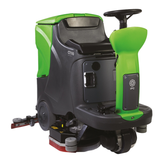
- Page 1 OPERATIONS MANUAL CT110...
-
Page 2: Table Of Contents
CONTENTS CONTENTS .......................... 2 GENERAL INFORMATION ....................4 2.1........................4 COPE OF THE MANUAL 2.2......................5 DENTIFYING THE MACHINE 2.3................5 OCUMENTATION PROVIDED WITH THE MACHINE TECHNICAL INFORMATION....................5 3.1........................5 ENERAL DESCRIPTION 3.2............................5 EGEND 3.3. - Page 3 ENGLISH...
-
Page 4: General Information
GENERAL INFORMATION Read this manual carefully before carrying out any work on the machine 2.1. Scope of the manual This manual has been written by the Manufacturer and is an integral part of the machine. It defines the purpose for which the machine has been designed and constructed and contains all the information required by operators. -
Page 5: Identifying The Machine
2.2. Identifying the machine The rating plate under the seat (fig. B, ref. 8) provides the following information: • model; • power supply; • total nominal power; • serial number; • year of fabrication; • weight fully loaded; • maximum slope; •... -
Page 6: Safety Information
D -Rear wheels: danger of crushing between the wheel and chassis. E -Battery compartment: danger of short circuit between the battery poles and presence of hydrogen during charging. SAFETY INFORMATION 4.1. Safety regulations Read the "User manual" carefully before start-up and use, or before performing maintenance or any other work on the machine. - Page 7 The operator must always use personal protection devices - protective apron or overalls, non-slip waterproof shoes, rubber gloves, protective goggles and ear protectors and mask to protect the respiratory tract. Keep the hands away from moving parts. Never use detergents other than those specified. Follow the instructions on the relative safety sheet.
- Page 8 If you decide to stop using the machine, you are recommended to remove the batteries and dispose of them at an authorised collection centre. You should also make sure that all parts of the appliance which could represent a hazard, particularly to children, are made safe.
-
Page 9: Handling And Installation
HANDLING AND INSTALLATION 5.1. Lifting and transporting the packaged machine IMPORTANT During all lifting operations, make sure the packaged machine is firmly anchored to avoid it tipping up or being accidentally dropped. Always load/unload lorries in adequately lit areas. The machine, packaged on a wooden pallet by the Manufacturer, must be loaded using suitable equipment (see EC Directive 89/392 and subsequent amendments and/or additions) onto the transporting vehicle. -
Page 10: Batteries: Preparation
The technical characteristics must correspond to those indicated in the paragraph on the technical specification of the machine. The use of heavier batteries could seriously jeopardise manoeuvrability and lead to the brush motor overheating. Batteries with a lower capacity and weight will require recharging more frequently. They must be kept charged, dry and clean and the connections must be tight. -
Page 11: The Battery Charger
6) Referring to the arrangement of cables shown in the diagram (fig. D), connect the battery cable and bridge terminals to the battery poles. Arrange the cables as shown in the diagram (fig. D), tighten the terminals on the poles and cover with Vaseline. -
Page 12: Practical Guide For The Operator
PRACTICAL GUIDE FOR THE OPERATOR 6.1. Controls - Description With reference to fig. A, the machine has the follow controls and indicator lights: • Power light (fig. A, ref. 5): consists of 4 LEDs indicating the battery charge level (see paragraph 6.7) •... -
Page 13: Mounting And Changing The Brush/Abrasive Disks
6.3. Mounting and changing the brush/abrasive disks IMPORTANT Never work without the brushes and abrasive disks perfectly installed. The terms RIGHT and LEFT refer to the forward movement of the machine Mounting the right brush (or abrasive disk) • remove the right and left side hatches (fig. L, ref. 2); •... -
Page 14: Adjusting The Riding Position
• via the opening (fig. C, ref. 5) under the seat, fill the solution tank (fig. B, ref. 1) with a suitable concentration of clean water and low-foam detergent. leave at least 5 cm between the surface of the liquid and the opening of the tank; •... - Page 15 speed on bends is therefore not a malfunction, but a feature which increases the machine's stability in all conditions. i INFORMATION To set the most suitable head pressure value and solution flow, press the brush button (fig. A, ref. 8) brushes on. •...
- Page 16 1 flashing red LED: battery voltage under 18 V (ACID batteries) or under 19 V (GEL batteries), drive is shut down. Recharge the batteries. 1 red LED on steadily: battery voltage between 18 and 20.5 V (ACID batteries) or 19 and 21.5 V (GEL batteries), SUPER-MINIMUM battery charge.
-
Page 17: Periods Of Inactivity
You should remove the handwheel (fig. F, ref. 1) and screw it onto the electromagnetic brake only for the time strictly necessary to push or pull the machine. PERIODS OF INACTIVITY If the machine is not used for some time, remove the squeegee and brushes (or abrasive disks), wash them and put them away in a dry place (preferably in a bag or wrapped in plastic film) away from dust. -
Page 18: Maintenance - General Rules
Maintenance on the electrical circuit and all other operations not explicitly described in this manual must be performed by specialised personnel only, in compliance with current safety legislation and as described in the maintenance manual. 9.1. Maintenance - General rules Performing regular maintenance according to the Manufacturer's instructions improves performance and extends the working life of the machine. -
Page 19: Fuses: Replacing
• reuse the same blade by reversing the edge in contact with the floor until all four edges are worn out, or replace with a new blade, fitting it onto the screws on the body of the squeegee (fig. I ref. 1); •... -
Page 20: Troubleshooting And Error Codes
TROUBLESHOOTING AND ERROR CODES 10.1. How to resolve possible problems PROBLEM CAUSE SOLUTION the batteries are disconnected connect batteries machine does machine function the batteries are flat recharge the batteries The emergency button is pressed (fig. H Press the emergency button (fig. - Page 21 Electromagnetic brake lock machine does (fig. F Screw up the handwheel (fig. F ref. brake handwheel unscrewed ref. 1) see paragraph 6.7 Electromagnetic brake malfunction replace The batteries do not last as the battery poles and terminals are clean and grease the poles and dirty and oxidised terminals, charge the batteries long as usual...
- Page 22 the battery charger does not work make sure there is voltage to the battery charger, that the fuses are not blown and that the current reaches the battery; try charging with another rectifier. If the battery charger is not working, contact the technical service centre...
-
Page 23: Alarms Displayed
10.2. Alarms displayed NO24 Battery below minimum level (18V) NOFR Main fuse blown or power relay malfunction NOEP EEPROM management error FH20 No water in tank. SH20 Dirty water tank full Machine shutting down R (xxx) Software release CD (xx) Chemical DOSE quantity SEGG Motor drive board deactivated (operator not seated). -
Page 24: Motor Drive Alarm Board
10.3. Motor drive alarm board (fig. C ref. 6). The board controlling the motor drive is located inside the front upright If drive is interrupted, the error code should be identified by means of the status LED. In the absence of malfunctions, the status LED is steadily on while the machine is in operation.
Need help?
Do you have a question about the CT110 and is the answer not in the manual?
Questions and answers