Table of Contents
Advertisement
Advertisement
Table of Contents

Subscribe to Our Youtube Channel
Related Manuals for JRC JMA-1032


Summary of Contents for JRC JMA-1032
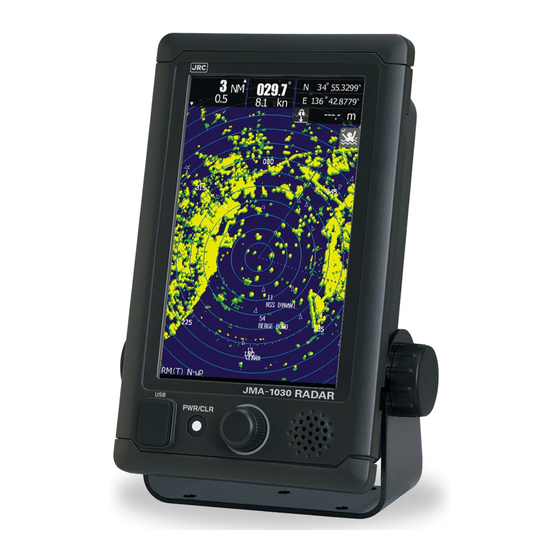
- Page 1 JMA-1030Series MARINE RADAR EQUIPMENT INSTRUCTION MANUAL...
- Page 3 PRECAUTIONS BEFORE OPERATION PRECAUTIONS BEFORE OPERATION ■ Cautions for high voltage High voltages from hundreds volts to tens of thousands volts are to be applied to the electronic equipment such radio and radar devices. You do not face any danger during normal operation, but sufficient cares are required for maintenance, inspection and adjustment of their internal components.
- Page 4 FIRST-AID TREATMENTS FIRST-AID TREATMENTS ■ First-aid treatments As far as the victim of electric shock is not in dangerous condition, do not move him and practice artificial respiration on him immediately. Once started, it should be continued rhythmically. Do not touch the victim confusedly as a result of the accident, but the rescuer may also get an electric shock.
- Page 5 FIRST-AID TREATMENTS When pulse is beating but breathing has stopped ■ (Mouth-to-mouth respiration) Fig. 1 Tilt the victim's head back as far as this face looks back. (A pillow may be inserted his neck. ) Push his jaw upward to open his throat wide (to spread his airway). Pinch the victim's nostrils and take a deep breath, block his mouth completely with yours and blow into his mouth strongly.
- Page 6 FIRST-AID TREATMENTS When both pulse and breathing have stopped ■ Perform the (Cardiac massage) Fig. 2 and (Mouth-to-mouth respiration) Fig. 1 When no pulse has come not to be felt, his pupils are open and no heartbeat is heard, cardiac arrest is supposed to have occurred and artificial respiration must be performed.
-
Page 7: Preface
PREFACE PREFACE Thank you very much for purchasing the JRC marine radar equipment, JMA-1030 series. This equipment is a marine radar equipment designed to obtain safe operation of marine ships. This equipment consists of a scanner unit and a display unit as its main units. - Page 8 Standard supply items are as follows. The normal installation cable length is 10m between scanner and display. Optional special length cables are prepared by JRC if request. Standard cable length is 10m. Optional special length cables are 5m, 15m, 20m 30m each.
-
Page 9: Before Operation
BEFORE OPERATION BEFORE OPERATION PICTORIAL INDICATION ■ Various pictorial indications are included in this manual and are shown on these equipment so that you can operate them safety and correctly and prevent any danger to you and/or to other persons and any damage to your property during operation. - Page 10 BEFORE OPERATION WARNING LABEL ■ Warning label is patched on the equipment visible surface. Do not try to remove, break or modify the label. viii...
- Page 11 BEFORE OPERATION RUSSIA CTP MARK ■ According to the requirements of clause 20 of Technical Regulations about safety of Maritime transport objetcs, approved by Resolution of the Russian Federation Goverment #620 dated August 12, 2010 and requirements Technical Regulation of the Russian Federation Goverment #623 dated August 12, 2010 navigation &...
-
Page 12: Precautions
PRECAUTINS PRECAUTIONS DANGER Never carry out internal inspection or repair work of the equipment by users. Inspection or repair work by unauthorized personnel may result in fire hazard or electric shock. For inspection and repair work of equipment components, consult with our branch office, branch shop, sales office, or our distributor in your district. - Page 13 PRECAUTINS WARNING Never directly touch the internal components of the antenna, receiver/transceiver, or indicator. Direct contact with these high-voltage components may cause electrocution. For maintenance, inspection, or adjustment of equipment components, consult with our branch office, branch shop, sales office, or our distributor in your district. Microwave radiation level: Keep away from a scanner when it is transmitting.
- Page 14 PRECAUTINS CAUTION A malfunction may occur if the power in the ship is instantaneously interrupted during operation of the radar. In this case, the power should be turned on again. Always use the automatic tuning mode. Use the manual tuning mode only when the automatic tuning mode does not provide the best tuning state due to deterioration of magnetron for example.
- Page 15 PRECAUTINS CAUTION Target Tracking Function Test is provided to test if the target tracking function is operating normally. Thus, do not use the function except when you test the target tracking function. Note especially that, if this function is used during actual navigation, simulated targets are displayed and may become confused with other actual targets.
- Page 16 PRECAUTINS CAUTION When replacing magnetrons, make sure to shut off the main power and let the equipment stand for more than 5 minutes to discharge the high-voltage circuit. Failure to comply may result in electrocution. Make sure to take off your watch when your hand must get close to the magnetron.
-
Page 17: Warning Label Mounting Point
WARNING LABEL MOUNTING POINT WARNING LABEL MOUNTING POINT NKE-1066 SCANNER UNIT View from cable inlet side. - Page 18 WARNING LABEL MOUNTING POINT NKE-2044 SCANNER UNIT View from cable inlet side.
-
Page 19: Equipment Appearance
(NKE-1066) (NKE-2044) Radome diameter 450mm Radome diameter 620mm CFQ9924-5,10,15,20,30 *STANDARD LENGTH 10m OPTION: (Cable length: 5m/15m/20m/30m) JMA-1034 ADAR JMA-1032 RADAR External Navigational Signal input. NMEA 3 input ports (GPS,AIS,DEPTH) Ship’s Main Power (10.8-31.2VDC) CFQ-9900 7inch WIDE VGA COLOUR LCD DISPLAY... - Page 20 DISPLAY APPEARANCE DISPLAY APPEARANCE DISPLAY TYPE NAME NCD-2256 TABLE TOP MOUNTING FRONT PANEL SUN COVER TOUCH PANEL USB PORT POWER/CLR PUSH SWITCH ROTARY KNOB WITH PUSH SPEAKER MOUTING BRANCKET REAR CASE xviii...
- Page 21 SCANNER APPEARANCE SCANNER APPEARANCE 1.5-FT SCANNER NKE-1066 SCANNER NKE-2044 NCD-2256 + NKE-1066 NCD-2256 + NKE-2044...
-
Page 23: Table Of Contents
CONTENTS CONTENTS PREFACE..........................v CHECKING THE SUPPLIED ITEMS.................vi BEFORE OPERATION ......................vii PRECAUTIONS ........................x WARNING LABEL MOUNTING POINT ................xv EQUIPMENT APPEARANCE..................xvii CONTENTS ..........................A GLOSSARY...........................a Chapter 1 INSTALLATION....................1 1-1 OVERVIEW .................. 1 1-2 INSTALLATION OF THE DISPLAY UINT ......... 2 1-2-1 SELECTING THE INSTALLATION POSITION.............. 2 1-2-2 SELECTION OF DISPLAY MOUNTING ................ -
Page 24: Contents
CONTENTS 3-2 ADJUSTS GAIN (RADAR SENSITIVITY) ........55 3-3 ADJUST SEA (CLUTTER CONTROL) ..........56 3-4 ADJUST RAIN AND SNOW CLUTTER CONTROL ......57 3-5 ADJUST BRILLIANCE OF SCREEN ..........58 Chapter 4 MEASURE THE SURROUND SHIPS ............60 4-1 MEASURE DIRECTION AND RANGE USING VRM/EBL ....60 4-1-1 ICON DISPLAY...................... - Page 25 CONTENTS 7-9-1 HEADING SIGNAL DEVICE SELECT................94 7-9-2 MANUAL HEADING INPUT..................95 7-9-3 SPEED INPUT SELECTION ..................95 7-9-4 MANUAL SPEED INPUT ....................96 7-9-5 MAGNETIC COMPASS SETUP ................96 Chapter 8 DETAIL PERFORMANCE SETTING............97 8-1 RADAR ECHO SETUP..............97 8-1-1 MAIN BANG SUPPRESSION..................
- Page 26 CONTENTS 8-8-1 SCANNER........................131 8-8-2 DISPLAY UNIT ......................133 8-8-3 CONNECTION DEVICE ....................135 8-8-4 RX DATA ........................136 Chapter 9 MAINTENANCE AND CHECK..............138 9-1 ROUTINE MAINTENANCE ............138 9-2 MAINTENANCE OF EACH UNIT ..........139 9-2-1 SCANNER NKE-1066....................139 9-2-2 SCANNER NKE-2044....................
- Page 27 CONTENTS 12-2-1 NCD-2256......................161 12-3 EQUIPMENT OUTLINE ............. 163 12-3-1 CONFIGULATION ..................... 163 12-3-2 FEATURE ........................163 12-3-3 RADAR MODEL ......................163 12-3-4 SYSTEM DIAGRAM....................164 12-4 GENERAL SPECIFICATIONS ............ 165 12-5 SCANNER................166 12-5-1 SCANNER (NKE-1066) SPECIFICATION ............... 166 12-5-2 SCANNER (NKE-2044) SPECIFICATION ...............
-
Page 29: Glossary
GLOSSARY GLOSSARY This section describes the main terms used for this equipment and general related maritime terms. Acquisition/Activation zone A zone set up by the operator in which the system should automatically acquire radar targets and activate reported AIS targets when entering the zone. Activated target A target representing the automatic or manual activation of a sleeping target for the display of additional information. - Page 30 GLOSSARY Electronic Bearing Line An electronic bearing line originated from own ship’s position. Enhance Estimated Time of Arrival Ground stabilization A display mode in which speed and course information are referred to the ground, using ground track input data. Heading The horizontal direction that the bow of a ship is pointing at any instant, expressed in angular units from a reference direction.
- Page 31 GLOSSARY Parallel Index line Past positions Equally time-spaced past position marks of a tracked or AIS target and own ship. POSN Position Pulse Repetition Frequency The number of radar pulses transmitted each second. PROC Process Radar signal processing function Radar beacon A navigation aid which responds to the radar transmission by generating a radar signal to identify its position and identity Radar cross-section Radar cross-section of a target determines the power density returned to the...
- Page 32 GLOSSARY SART Search And Rescue Transponder Radar transponder capable of operating in the 9GHz band Sea stabilization A display mode in which speed and course information are referred to the sea. Sea state Status of the sea condition due to the weather environment, expressed as a sea state 0 for flat conditions with minimal wind, to sea state 8 for very rough sea conditions.
- Page 33 GLOSSARY Universal Time Coordinated. The international standard of time, kept by atomic clocks around the world. Variable Range Marker An adjustable range ring used to measure the distance to a target. Waypoint A geographical location on a route indicating an event. GLOSSARY-e...
-
Page 35: Chapter 1 Installation
■ Available cable lengths and types for installing the radar JMA-1030 are as shown in the table below. Request an appropriate cable from JRC beforehand. A cable longer than the sufficient length may degrade radar performance, so give it careful consideration when planning the installation. -
Page 36: Installation Of The Display Uint
Chapter 1 INSTALLATION 1 - 2 IN S T A LL A TI O N O F T H E DI S P L A Y UI N T 1-2-1 SELECTING THE INSTALLATION POSITION Select the display unit installation position by taking into consideration the following. ■... -
Page 37: Dimensional Drawing Of Display Mounting
Chapter 1 INSTALLATION 1-2-3 DIMENSIONAL DRAWING OF DISPLAY MOUNTING... - Page 38 Chapter 1 INSTALLATION...
-
Page 39: Examples Of Display Mounting
Chapter 1 INSTALLATION 1-2-4 EXAMPLES OF DISPLAY MOUNTING DESK TOP INSTALLATION ■ Standard mounting base. - Page 40 Chapter 1 INSTALLATION Disktop Mounting Template.
- Page 41 Chapter 1 INSTALLATION ■ FLUSH MOUNT Front cap Flash mount: Remove base, and take out cover of front panel Fix with the front 4corner screws to the wall.
- Page 42 Chapter 1 INSTALLATION Flush Mounting Template...
- Page 43 Chapter 1 INSTALLATION CEILING INSTALLATION ■ Option: fixation tool.
-
Page 44: Power Cable Installation
Chapter 1 INSTALLATION 1-2-5 POWER CABLE INSTALLATION This radar includes 2m power cable, which radar side was already ended with connector. Cable assembly name: CFQ-9900 The cable’s core color is white (+), black (-) ,shield mesh + green (frame ground). Wire : AWG16 The fuse box is built into the cable (white line side). -
Page 45: External Navigational Signal Connection
Chapter 1 INSTALLATION 1-2-6 EXTERNAL NAVIGATIONAL SIGNAL CONNECTION (GPS, AIS, GYRO, LOG, etc.) Connecting cable is option Navigation system interfaces, such as GPS Telecommunications standard NMEA0183 / 61162 to 1EC1 conformity Communications protocol: 4800 bps, start 1bit, data 8bit, stop 1bit, and no parity Input sentence NMEA0183: V1,5 : GGA/ GLL/ RMC... -
Page 46: Installation Of The Scanner Unit
Chapter 1 INSTALLATION 1 - 3 IN S T A LL A TI O N O F T H E S C AN N E R U NI T 1-3-1 SELECTING THE INSTALLATION POSITION ■ PHYSICAL SELECTION CRITERIA ■ Install the scanner at the center of the mast on the keel line. ■... -
Page 47: Lowest Scanner Installation Height
Chapter 1 INSTALLATION 1-3-2 LOWEST SCANNER INSTALLATION HEIGHT JMA-1030 : θ= 12.5 ° 2θ= 25 ° Fig. 1-3-2 ■ If it is considered that sufficient installation height cannot be provided when the scanner is installed directly on the roof of the wheelhouse, use a mounting rack or radar mast (Fig. -
Page 48: Scanner And The Surrounding Structural Objects
Chapter 1 INSTALLATION 1-3-4 SCANNER AND THE SURROUNDING STRUCTURAL OBJECTS Vertical beam width of X-band: Approx. 20° (+/-10.0° when the height of the radiating section is 0°). Fig. 1-3-4 When installing two scanners, provide a height difference so that those two scanners do not enter each other's vertical beam width range. -
Page 49: Ensuring View Angle
Chapter 1 INSTALLATION 1-3-5 ENSURING VIEW ANGLE direction Make no blind sector Fig. 1-3-5 ■ Magnetron which has strong magnetic force is included in the scanner. Install the scanner at least 3 meters away from nautical instruments including magnetic compasses and chronometers. * If there is a concern that structural objects existing within the vertical beam width may generate false images, equip the structural objects with a radio wave absorber. - Page 50 Chapter 1 INSTALLATION ■ Others ■ The design of the mounting platform for the scanner should take into account the vibration requirements defined by IEC 60945. Vibration Frequency 2 to 13.2 Hz 13.2 Hz to 100 Hz Amplitude +/-1 mm +/-10 % Acceleration 7m/s constant...
-
Page 51: Confirm Mounting Base Before Install
Chapter 1 INSTALLATION 1-3-6 CONFIRM MOUNTING BASE BEFORE INSTALL NKE-1066 1.5FT SCANNER 4-φ40 RUBBER PLATE Fig 1-3-6-1 Fig 1-3-6-2... - Page 52 Chapter 1 INSTALLATION NKE-2044 2 FT SCANNER Fig 1-3-6-3 Fig 1-3-6-4...
- Page 53 Chapter 1 INSTALLATION Installation and clamping method ■ Installation direction ■ Installation should be done so that the cable gland is oriented toward the stern. Bolts, nuts and tightening torque to be used ■ ■ Use stainless steel bolts for the scanner and uniformly tighten all of the bolts using double nuts for each bolt so that the scanner will not become loose (Table 1-2-1).
-
Page 54: Connecting The Installation Cable
Chapter 1 INSTALLATION 1 - 4 C O N N EC TI N G TH E IN S T A L L AT IO N C AB L E Scanner type is selected from two types. 2 ft scanner (NKE-2044) ,and 1.5 ft scanner(NKE-1066). Both are the radome type, they are no affect from the wind blow. -
Page 55: Nke-1066 Scanner(1.5Feet)
Chapter 1 INSTALLATION 1-4-1 NKE-1066 SCANNER(1.5FEET) Set the cable inlet side to stern. (Any direction is possible to install and possible to initial setup. , but it is better selection to select the cable length must be minimize along the mast.) stern Ship’s heading Fig. - Page 56 Chapter 1 INSTALLATION Fig. 1-4-1-3...
- Page 57 Chapter 1 INSTALLATION...
- Page 58 Chapter 1 INSTALLATION coating clip Connect cable’s mesh wire as Ground. Pull and fix the cable toward the outside with coating clip. (Aboid to touch the cable to electorical parts) Fig. 1-4-1-4...
-
Page 59: Nke-2044 Scanner (2Feet)
Chapter 1 INSTALLATION 1-4-2 NKE-2044 SCANNER (2FEET) Set the cable inlet side to stern. (Any direction is possible to install and possible to initial setup. , but it is better selection to select the cable length must be minimize along the mast.) Ship’s heading stern Fig. - Page 60 Chapter 1 INSTALLATION Fig. 1-4-2-3...
- Page 61 Chapter 1 INSTALLATION...
- Page 62 Chapter 1 INSTALLATION Connect cable’s mesh wire as Ground. Clamp whole cable Fig. 1-4-2-4...
Need help?
Do you have a question about the JMA-1032 and is the answer not in the manual?
Questions and answers