Sign In
Upload
Manuals
Brands
Lakeshore Manuals
Temperature Controller
335
Lakeshore 335 Manuals
Manuals and User Guides for Lakeshore 335. We have
1
Lakeshore 335 manual available for free PDF download: User Manual
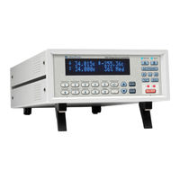
Lakeshore 335 User Manual (172 pages)
Brand:
Lakeshore
| Category:
Temperature Controller
| Size: 11.51 MB
Table of Contents
Table of Contents
7
Chapter 1 1.1 Product Description
13
Product Description
13
Sensor Inputs
14
Interface
15
Temperature Control
15
Configurable Display
16
Model 3060 Thermocouple Input Option
16
Sensor Selection
17
Model 335 Specifications
19
Input Specifications
19
Control
20
Heater Outputs (Outputs 1 and 2)
20
Sensor Input Configuration
20
Thermometry
20
Front Panel
22
General
22
Interface
22
Safety Summary and Symbols
23
Cooling System Design and Temperature Control
25
General
25
Temperature Sensor Selection
25
Sensor Sensitivity
25
Temperature Range
25
Chapter 2 2.1 General
25
Environmental Conditions
26
Measurement Accuracy
26
Sensor Calibrations
26
Curve Handler
27
Precision Calibration
27
Sensors Using Standard Curves
27
Softcal
27
Sensor Package
26
Sensor Installation
28
Mounting Materials
28
Sensor Location
28
Thermal Conductivity
28
Contact Area
29
Contact Pressure
29
Lead Wire
29
Lead Soldering
30
Thermal Anchoring Leads
30
Thermal Radiation
31
Heater Selection and Installation
31
Heater Resistance and Power
31
Heater Location
32
Heater Types
32
Heater Wiring
33
Consideration for Good Control
33
Thermal Conductivity
33
Thermal Lag
33
Two-Sensor Approach
33
System Non-Linearity
34
Thermal Mass
34
PID Control
34
Derivative (D)
35
Integral (I)
35
Manual Output
35
Proportional (P)
35
Manual Tuning
37
Setting Heater Range
37
Tuning Proportional
37
Tuning Integral
38
Tuning Derivative
39
Autotuning
39
Thermoelectric Devices
40
Zone Tuning
40
General
41
Inspection and Unpacking
41
Chapter 3 3.1 General
41
Line Input Assembly
42
Line Voltage
42
Line Fuse and Fuse Holder
43
Power Cord
43
Power Switch
43
Rear Panel Definition
42
Diode/Resistor Sensor Inputs
43
Sensor Input Connector and Pinout
43
Grounding and Shielding Sensor Leads
44
Sensor Lead Cable
44
Four-Lead Sensor Measurement
45
Sensor Polarity
45
Lowering Measurement Noise
46
Two-Lead Sensor Measurement
46
Thermocouple Sensor Inputs (Thermocouple Model 3060)
47
Grounding and Shielding
47
Sensor Input Terminals
47
Thermocouple Installation
47
Heater Output Setup
48
Heater Output Connectors
48
Heater Output Description
48
Heater Output Wiring
48
Choosing a Power Supply
49
Heater Output Noise
49
Powering Output 2 Using an External Power Supply
49
Connecting to the Model 335
50
Power Supply Setup
50
Programming Voltages under 10 V
51
General
53
Understanding Menu Navigation
53
Chapter 4 4.1 General
53
Front Panel Description
54
Direct Operation Keys
54
Keypad Definitions
54
Menu/Number Pad Keys
54
Annunciators
55
General Keypad Operation
55
Display Setup
56
Display Modes
56
Two Input, One Loop Modes
56
Input Display Modes
57
Two Loop Mode
57
Custom Display Mode
58
Display Brightness
59
Input Setup
59
Diode Sensor Input Setup
60
Negative Temperature Coefficient (NTC) Resistor Sensor Input Setup
60
Positive Temperature Coefficient (PTC) Resistor Sensor Input Setup
60
Range Selection
61
Thermal Electromotive Force (EMF) Compensation
61
Internal Room Temperature Compensation
62
Internal Room Temperature Compensation Calibration Procedure
62
Thermocouple Sensor Input Setup (Model 3060 Only)
62
Curve Selection
63
Filter
64
Input Name
65
Temperature Limit
65
Max/Min
66
Preferred Units
66
Output and Control Setup
66
Heater Outputs
66
Configuration
67
Heater Output Type (Output 2)
67
Max Current and Heater Resistance
67
User Max Current
68
Power up Enable
69
Closed Loop PID Mode
70
Heater out Display
70
Output Modes
70
Zone Mode
70
Control Input
71
Control Parameters
71
Open Loop Mode
71
Integral (I)
72
Proportional (P)
72
Derivative (D)
73
Manual Output
73
Setpoint
74
Setpoint Ramping
75
All off
76
Heater Range
76
Voltage Output
76
Monitor out
77
Warm up Supply
77
Interface
77
Ieee-488
77
Remote/Local
77
Usb
77
Locking and Unlocking the Keypad
77
Advanced Operation
79
Autotune
79
Chapter 5 5.1 General
79
General
79
Zone Settings
81
Bipolar Control
83
Warm up Supply
83
Warm up Control
84
Warm up Percentage
84
Monitor out
84
Monitor Units
85
Polarity and Monitor out Scaling Parameters
85
Alarms and Relays
86
Alarm Annunciators
86
Alarms
86
Alarm Latching
87
Relays
88
Curve Numbers and Storage
89
Curve Breakpoints
89
Curve Header Parameters
89
Front Panel Curve Entry Operations
90
Edit Curve
90
Edit a Breakpoint Pair
91
Add a New Breakpoint Pair
92
Delete a Breakpoint Pair
92
Thermocouple Curve Considerations
92
Copy Curve
93
Erase Curve
93
Softcal
93
Softcal™ with Silicon Diode Sensors
94
Softcal™ Accuracy with DT-400 Series Silicon Diode Sensors
95
Softcal™ with Platinum Sensors
95
Softcal™ Accuracy with Platinum Sensors
96
Softcal™ Calibrationcurve Creation
96
Emulation Modes
97
Emulation Mode Configuration
97
Baud Rate
98
Command Interpretation
98
PID Scaling Mode
98
Unsupported Commands
98
Emulation Mode Differences
99
Hardware Differences
99
Computer Interface Operation
101
General
101
IEEE-488 Interface
101
Chapter 6 6.1 General
101
Changing IEEE-488 Interface Parameters
102
IEEE-488.2 Command Structure
102
Bus Control Commands
102
Common Commands
103
Device Specific Commands
103
Message Strings
103
Remote/Local Operation
102
Status System Overview
104
Condition Registers
104
Enable Registers
104
Event Registers
104
Programming Registers
106
Reading Registers
106
Service Request Enable Register
106
Status Byte Register
106
Clearing Registers
107
Status System Detail: Status Register Sets
107
Standard Event Status Register Set
107
Operation Event Register Set
108
Status System Detail: Status Byte Register and Service Request
109
Status Byte Register
109
Service Request Enable Register
110
Using Service Request (SRQ) and Serial Poll
110
Operation Complete Query (*OPC?)
111
Using Status Byte Query (*STB?)
111
Using the Message Available (MAV) Bit
111
USB Interface
112
Hardware Support
112
Installing the USB Driver
112
Physical Connection
112
Windows Vista® or Windows 7
112
Download the Driver
113
Extract the Driver
113
Installing the Driver from the Web
113
Installing the Driver from Windows® Update in Windows® XP
113
Manually Install the Driver
114
Installing the USB Driver from the Included CD
115
Character Format
116
Communication
116
Message Flow Control
116
Message Strings
116
Command Summary
117
Command Function
118
106 Chapter 106 106 Chapter 6: Computer Interface Operation
118
Command Function
118
CLS Clear Interface CMD
119
ESE Event Status Enable Register CMD
119
ESE? Event Status Enable Register Query
119
Interface Commands
119
ESR? Standard Event Status Register Query
120
IDN? Identification Query
120
OPC Operation Complete CMD
120
OPC? Operation Complete Query
120
RST Reset Instrument CMD
120
SRE Service Request Enable Register CMD
121
SRE? Service Request Enable Register Query
121
STB? Status Byte Query
121
TST? Self-Test Query
121
WAI Wait-To-Continue CMD
121
Alarm
122
ALARM? Input Alarm Parameter Query
122
ALARMST? Input Alarm Status Query
122
Almrst
122
Analog
123
ANALOG? Monitor out Parameter Query
123
Atune
123
Brigt
123
BRIGT? Display Brightness Query
124
CRDG? Celsius Reading Query
124
Crvdel
124
Crvhdr
124
CRVHDR? Curve Header Query
124
Crvpt
125
CRVPT? Curve Data Point Query
125
Dflt
125
DIOCUR Diode Excitation Current Parameter CMD
125
DIOCUR? Diode Excitation Current Parameter Query
125
Dispfld
126
DISPFLD? Custom Mode Display Field Query
126
Display
126
DISPLAY? Display Setup Query
126
Emul
127
Filter
127
FILTER? Input Filter Parameter Query
127
HTR? Heater Output Query
127
Model 331/332 Emulation Mode Query
127
Htrset
128
HTRSET? Heater Setup Query
128
HTRST? Heater Status Query
128
Ieee
128
IEEE? IEEE-488 Interface Parameter Query
129
Incrv
129
INCRV? Input Curve Number Query
129
Inname
129
INNAME? Sensor Input Name Query
129
Intype
130
INTYPE? Input Type Parameter Query
130
KRDG? Kelvin Reading Query
131
Leds
131
LEDS? Front Panel LEDS Query
131
Lock
131
LOCK? Front Panel Keyboard Lock Query
131
MDAT? Minimum/Maximum Data Query
131
Mnmxrst
131
Mode
132
MODE? Remote Interface Mode Query
132
Mout
132
MOUT? Output Manual Heater Power (MHP) Output Query
132
OPST? Operational Status Query
132
Opste
132
OPSTE? Operational Status Enable Query
132
Opstr?
133
OUTMODE Output Mode Command
133
OUTMODE? Output Mode Query
133
PID Control Loop PID Values CMD
133
PID? Control Loop PID Values Query
133
POLARITY Output Voltage Polarity Command
134
POLARITY? Output Voltage Polarity Query
134
Ramp
134
RAMP? Control Setpoint Ramp Parameter Query
134
RAMPST? Control Setpoint Ramp Status Query
134
Range
135
RANGE? Heater Range Query
135
RDGST? Input Reading Status Query
135
Relay
135
RELAY? Relay Control Parameter Query
135
RELAYST? Relay Status Query
136
Scal
136
Setp
136
SETP? Control Setpoint Query
136
SRDG? Sensor Units Input Reading Query
137
TEMP? Thermocouple Junction Temperature Query
137
Tlimit
137
TLIMIT? Temperature Limit Query
137
TUNEST? Control Tuning Status Query
137
Warmup
138
WARMUP? Warmup Supply Parameter Query
138
Zone
138
ZONE? Output Zone Table Parameter Query
138
General
139
Models
139
Options
139
Chapter 7 7.1 General
139
Options and Accessories
139
Rack Mounting
141
Model 3060-H Thermocouple Input Option
142
Model 3003 Heater and Output Conditioner
143
General
145
USB Troubleshooting
145
Existing Installation no Longer Working
145
Intermittent Lockups
145
New Installation
145
Chapter 8 8.1 General
145
Fuse Drawer
146
IEEE Interface Troubleshooting
146
Existing Installation no Longer Working
146
Intermittent Lockups
146
New Installation
146
Line Voltage Selection
146
Fuse Replacement
147
Factory Reset Menu
148
Default Values
148
Product Information
149
Calibration Procedure
149
Error Messages
149
Rear Panel Connector Definition
150
IEEE-488 Interface Connector
152
Electrostatic Discharge
153
Handling Electrostatic Discharge Sensitive Components
153
Identification of Electrostatic Discharge Sensitive Components
153
Model 3060 Installation
153
Firmware Updates
155
Updating the Firmware
155
Technical Inquiries
156
Contacting Lake Shore
156
Return of Equipment
156
RMA Valid Period
156
Restocking Fee
157
Shipping Charges
157
Advertisement
Advertisement
Related Products
Lakeshore 325
Lakeshore 340
Lakeshore 332
Lakeshore 331E
Lakeshore 331S
Lakeshore 330
Lakeshore 336
Lakeshore 3f Wye
Lakeshore 3f Delta
Lakeshore 3f Polyphase
Lakeshore Categories
Temperature Controller
Indoor Furnishing
Measuring Instruments
Power Supply
Controller
More Lakeshore Manuals
Login
Sign In
OR
Sign in with Facebook
Sign in with Google
Upload manual
Upload from disk
Upload from URL