Table of Contents
Advertisement
Quick Links
INSTALLATION INSTRUCTIONS
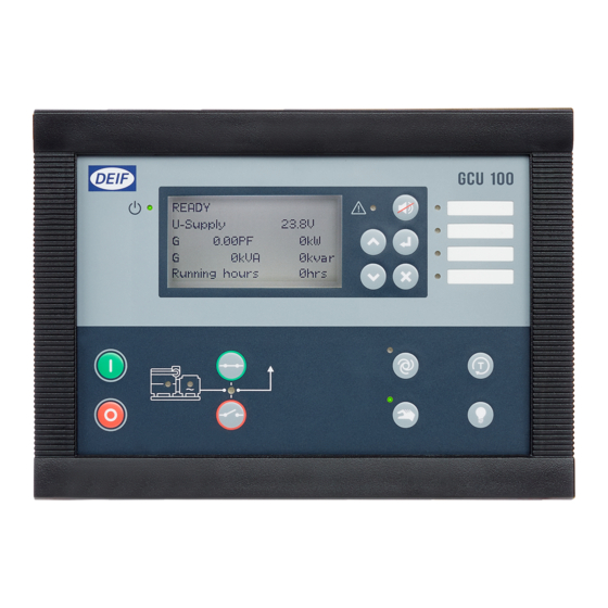
Genset Controller Unit, GCU 100
● Mounting
● Terminal overview
● Wiring
● Communication wiring
● Unit dimensions and cut-out
DEIF A/S · Frisenborgvej 33 · DK-7800 Skive · Tel.: +45 9614 9614 · Fax: +45 9614 9615 · info@deif.com · www.deif.com
Document no.: 4189340799D
SW version:
Advertisement
Table of Contents

Related Manuals for Deif GCU 100


Summary of Contents for Deif GCU 100
- Page 1 ● Unit dimensions and cut-out DEIF A/S · Frisenborgvej 33 · DK-7800 Skive · Tel.: +45 9614 9614 · Fax: +45 9614 9615 · info@deif.com · www.deif.com isenborgvej 33 · DK-7800 Skive · Tel.: +45 9614 9614 · Fax: +45 9614 9615 · info@deif.com · www.deif.com Document no.: 4189340799D...
-
Page 2: Table Of Contents
GCU 100 installation instructions 4189340799 UK 1. General information 1.1. Warnings, legal information and safety....................3 1.1.1. Warnings and notes ........................3 1.1.2. Legal information and disclaimer ....................3 1.1.3. Safety issues ..........................3 1.1.4. Electrostatic discharge awareness ....................3 1.1.5. Factory settings ..........................4 1.1.6. UL applications..........................4 1.2. -
Page 3: General Information
1.1.2 Legal information and disclaimer DEIF takes no responsibility for installation or operation of the generator set. If there is any doubt about how to install or operate the engine/generator controlled by the Multi-line 2 unit, the company responsible for the installation or the operation of the set must be contacted. -
Page 4: Factory Settings
GCU 100 installation instructions General information 4189340799 UK 1.1.5 Factory settings The Multi-line 2 unit is delivered from factory with certain factory settings. These are based on average values and are not necessarily the correct settings for matching the engine/generator set in question. Precautions must be taken to check the settings before running the engine/generator set. -
Page 5: Mounting
GCU 100 installation instructions Mounting 4189340799 UK 2. Mounting 2.1 GCU 100 mounting 2.1.1 Mounting of the unit Included in the package is 12 fixing clamps. The unit is designed for flush mounting for both IP52 and IP65 mounting. For IP52, four fixing clamps are to be used;... -
Page 6: Tightening Torques
GCU 100 installation instructions Mounting 4189340799 UK 220.0 (8.66) 211.0 (8.30) 2.1.3 Tightening torques Unit panel door mounting: 0.15-0.20 Nm, 1.4-1.8 lb-in (see diagram in "Unit dimensions and panel cut- out") Plug connections (terminals): 0.5 Nm, 4.4 lb-in AOP-1 and AOP-2 (see diagram below) Panel door mounting: 0.7 Nm, 6.2 lb-in... - Page 7 GCU 100 installation instructions Mounting 4189340799 UK 220.0 (8.661) 0.2 Nm Display 9P Female Sub 0 connector 0.7 Nm Screw M3 Max. 10 mm Bossard BN5687 Min. 6 mm or similar 20.0 (0.787) DEIF A/S Page 7 of 31...
-
Page 8: Terminals
GCU 100 installation instructions Terminals 4189340799 UK 3. Terminals 3.1 Terminal overview and description 3.1.1 Terminal overview Unit rear view 10 11 12 13 14 15 16 19 20 23 24 25 26 27 Power Multi-functional Digital inputs RPM inputs Emer. - Page 9 GCU 100 installation instructions Terminals 4189340799 UK Terminal Technical data Description Power supply + 6…36V DC (UL/cUL Listed: 7.5…32.7V DC) Power supply – 0V DC Status out/configurable. Contact ratings 1 A See note* 24V DC/V AC Resistive Common Common for term. 10…15...
- Page 10 GCU 100 installation instructions Terminals 4189340799 UK Terminal Technical data Description Not used, must not be connected Gen. voltage L3 3-phase generator current input Gen. current L1, s1 Generator current Gen. current L1, s2 Gen. current L2, s1 Gen. current L2, s2 Gen.
- Page 11 GCU 100 installation instructions Terminals 4189340799 UK * The status relay is the uP watchdog output. This relay is normally energised, and the switch is closed after power-up. If the uP fails or the power is lost, the relay will de-energise and the switch will open. If the unit fails to start up at power-up, then the relay switch will remain open.
-
Page 12: Wiring
GCU 100 installation instructions Wiring 4189340799 UK 4. Wiring 4.1 Wiring diagram Controller Charging alternator Running 1N4007 Programming tool Alarm RJ11 plug Alarm horn Oli pressure RUN coil Coolant temp. Starter Overspeed Start prep. Emer. STOP Remote start Start enable... -
Page 13: Dc Connections
GCU 100 installation instructions Wiring 4189340799 UK 4.2 DC connections Engine communication Modbus External I/O and AOP 2 Controller Controller Controller CAN H B (-) CAN H CAN L A (+) CAN L Multi-functional inputs, Multi-functional inputs, Multi-functional inputs, RMI sensors... -
Page 14: Digital Inputs
GCU 100 installation instructions Wiring 4189340799 UK 4.3 Digital inputs All digital inputs are 12/24V DC bi-directional optocoupler type. The typical wiring is illustrated below: The digital inputs use fixed signals. Only the mode shift input and the test input (if the timer is used) use pulse signal. - Page 15 GCU 100 installation instructions Wiring 4189340799 UK Running feedback Run coil input Battery 1N4007 Brush Exciter Charger coil (rotor) alternator Brush Stator Excitation controller Rex: Excitation resistor 12 V systems: 47 Ω 4 W 24 V systems: 100 Ω 6 W At standstill, the battery + is connected to terminal 9 (common), and a current flows to terminal 12 and via the D+ input on the alternator to ground (battery -).
-
Page 16: Gcu Wiring Diagrams For Voltage And Current
GCU 100 installation instructions Wiring 4189340799 UK 4.5 GCU wiring diagrams for voltage and current 4.5.1 GCU 113 3-phase BUSBAR GCU 113 BUSBAR VOLTAGE TB OFF command TB ON command Consumers GB ON command GB OFF command GENERATOR VOLTAGE GENERATOR... - Page 17 GCU 100 installation instructions Wiring 4189340799 UK 2-phase L1L2 BUSBAR GCU 113 BUSBAR VOLTAGE TB OFF command TB ON command Consumers GB ON command GB OFF command GENERATOR VOLTAGE GENERATOR CURRENT GENERATOR DEIF A/S Page 17 of 31...
- Page 18 GCU 100 installation instructions Wiring 4189340799 UK 2-phase L1L3 BUSBAR GCU 113 BUSBAR VOLTAGE TB OFF command TB ON command Consumers GB ON command GB OFF command GENERATOR VOLTAGE GENERATOR CURRENT GENERATOR DEIF A/S Page 18 of 31...
- Page 19 GCU 100 installation instructions Wiring 4189340799 UK 1-phase BUSBAR GCU 113 BUSBAR VOLTAGE TB OFF command TB ON command Consumers GB ON command GB OFF command GENERATOR VOLTAGE GENERATOR CURRENT GENERATOR DEIF A/S Page 19 of 31...
-
Page 20: Gcu 112
GCU 100 installation instructions Wiring 4189340799 UK 4.5.2 GCU 112 3-phase BUSBAR GCU 112 BUSBAR VOLTAGE GB ON command GB OFF command GENERATOR VOLTAGE GENERATOR CURRENT GENERATOR DEIF A/S Page 20 of 31... - Page 21 GCU 100 installation instructions Wiring 4189340799 UK 2-phase L1L2 BUSBAR GCU 112 BUSBAR VOLTAGE GB ON command GB OFF command GENERATOR VOLTAGE GENERATOR CURRENT GENERATOR DEIF A/S Page 21 of 31...
- Page 22 GCU 100 installation instructions Wiring 4189340799 UK 2-phase L1L3 BUSBAR GCU 112 BUSBAR VOLTAGE GB ON command GB OFF command GENERATOR VOLTAGE GENERATOR CURRENT GENERATOR DEIF A/S Page 22 of 31...
- Page 23 GCU 100 installation instructions Wiring 4189340799 UK 1-phase BUSBAR GCU 112 BUSBAR VOLTAGE GB ON command GB OFF command GENERATOR VOLTAGE GENERATOR CURRENT GENERATOR DEIF A/S Page 23 of 31...
-
Page 24: Gcu 111
GCU 100 installation instructions Wiring 4189340799 UK 4.5.3 GCU 111 3-phase Consumer GCU 111 GENERATOR VOLTAGE GENERATOR CURRENT GENERATOR DEIF A/S Page 24 of 31... - Page 25 GCU 100 installation instructions Wiring 4189340799 UK 2-phase L1L2 Consumer GCU 111 GENERATOR VOLTAGE GENERATOR CURRENT GENERATOR DEIF A/S Page 25 of 31...
- Page 26 GCU 100 installation instructions Wiring 4189340799 UK 2-phase L1L3 Consumer GCU 111 GENERATOR VOLTAGE GENERATOR CURRENT GENERATOR DEIF A/S Page 26 of 31...
- Page 27 GCU 100 installation instructions Wiring 4189340799 UK 1-phase Consumer GCU 111 GENERATOR VOLTAGE GENERATOR CURRENT GENERATOR DEIF A/S Page 27 of 31...
-
Page 28: Communication
GCU 100 installation instructions Communication 4189340799 UK 5. Communication 5.1 Wiring instructions Cable Belden 3106 A or equivalent. 22 AWG (0.324 mm ) shielded twisted pair, min. 95 % shield coverage. Cable shield Connect the cable shield to earth at one end only. -
Page 29: Canbus Engince Communication
GCU 100 installation instructions Communication 4189340799 UK 5.2 CANbus engince communication 5.2.1 Connection with 2-wire shielded cable (recommended) Multi-line 2 engine control module DEIF A/S Page 29 of 31... -
Page 30: Connection With 3-Wire Shielded Cable
GCU 100 installation instructions Communication 4189340799 UK 5.2.2 Connection with 3-wire shielded cable Multi-line 2 engine control module DEIF A/S Page 30 of 31... -
Page 31: Additional Operator Panel, Aop-2
GCU 100 installation instructions Communication 4189340799 UK 5.3 Additional Operator Panel, AOP-2 Additional operator´s panel AOP-2 CAN L CAN H CAN 1 CAN 2 R=120 Ω 5V DC Terminal block DIN rail 24V DC Comm. to next units Cable shield Status relay 1...6...
Need help?
Do you have a question about the GCU 100 and is the answer not in the manual?
Questions and answers