Table of Contents
Advertisement
Quick Links
Download this manual
See also:
Instruction Manual
Advertisement
Table of Contents

Related Manuals for Pulsar FLOW PULSE


Summary of Contents for Pulsar FLOW PULSE
- Page 1 Flow Pulse Handheld NSTRUCTION ANUAL...
- Page 3 ARRANTY AND IABILITY Pulsar Process Measurement Limited guarantee for a period of 2 years* from the date of delivery that it will either exchange or repair any part of this product returned to Pulsar Process Measurement Limited if it is found to be defective in material or workmanship, subject to the defect not being due to unfair wear and tear, misuse, modification or alteration, accident, misapplication or negligence.
-
Page 5: Table Of Contents
Totaliser Multiplier ............................32 Exporting Log Files to Excel ..........................33 Flow Pulse Parameter Files........................... 33 Loading a Parameter File onto Flow Pulse ....................34 System Information ............................... 35 Internal Storage ..............................35 Upgrading Firmware on the Flow Pulse Handheld ................35 Flow Pulse Handheld Parameters .................. - Page 6 Troubleshooting the Handheld Controller ......................43 Sensor not connected ............................ 43 Controller does not switch on ........................44 Battery level drops too quickly ........................45...
-
Page 7: Chapter 1 Introduction
Chapter 1 Introduction Flow Pulse Handheld Congratulations on your purchase of a Pulsar It has been designed to give you years of trouble free performance, and a few minutes spent reading this operation manual will ensure that your installation is as simple as possible. -
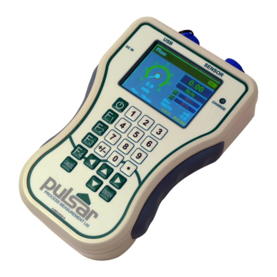
Page 8: About The Flow Pulse Handheld Controller
About the Handheld Controller Flow Pulse Flow Pulse Handheld is designed specifically for use with the Flow Pulse sensor. It is a complete, battery-powered, portable platform Flow Pulse that complements the , offering the ability to view traces, perform data logging, as well as to save and program parameters on the... -
Page 9: Product Specification
In-car charger Power supply DC 12-18V, Power Consumption 3.5W @ 12V not charging 15W @ 12V when charging Pulsar Process Measurement Limited operates a policy of constant development and improvement and reserve the right to amend technical details as necessary. Page... -
Page 10: Eu Declaration Of Conformity
EU Declaration of Conformity Page 10... -
Page 11: Setup And Quick Start
Power-up the and verify each cable core by measuring its voltage. Important Information Please ensure that when carrying the Flow Pulse and Flow Pulse Handheld the cable is held out of the way as it is a tripping hazard. Page... - Page 12 Flow Pulse Handheld Flow For reference when connecting the to the Pulse Flow Pulse Flow Pulse the connections on both the and the Handheld are shown below. The table describes the connections between the two. Flow Pulse Flow Pulse Handheld...
-
Page 13: Dimensions
Dimensions Page... -
Page 14: Key Guide
Toggle continuous data logging on/off Cancel Sleep/Wake logging (when device is awake) Stop file replay (only during file replay session) Jump to Flow Pulse setting menu Increase screen brightness (when pressed repeatedly) Jump to Handheld setting menu Decrease screen brightness (when pressed repeatedly) -
Page 15: Connecting To A Flow Pulse
Connecting to a Flow Pulse Flow Pulse Handheld Flow can be connected to any existing Pulse Flow monitoring, diagnostic trace and normal data logging functions are supported. Flow Pulse However, the following features will only be supported by firmware 1.2.4 and later:... - Page 16 This page is left blank intentionally Page 16...
-
Page 17: Chapter 3 Operating The Controller
Fahrenheit). Never submerge the controller in liquid. Always power-down device, disconnect charger or any external power source and unplug sensor connector before performing any servicing to the Flow Pulse Handheld Flow Pulse or the Charging the Controller A charger is supplied for charging the battery on the handheld. Other chargers may be used, but the power rating must be within 12-18 VDC and fused @ 2A max. -
Page 18: User Interface Structure
Flow Pulse Always disconnect the charger and the sensor before attempting any form of cable or wire servicing. Flow Pulse Handheld has an internal temperature sensor that Flow Pulse monitors board temperature and will power-down the Handheld and taper charging rate when temperature rises beyond the specified threshold. -
Page 19: Flow Window
The main window is the Flow window. This page displays both the flow velocity and the associated flow rate. The expected mA output on the Flow Pulse and the name of site for data logging are also shown. The units of flow rate can be changed in Setting1 ... -
Page 20: Diagnostic Trace Window
Diagnostic Trace Window Trace Flow Flow Pulse The Trace window displays the diagnostic trace from the The red dot on the trace indicates the amount of flow perceived by the sensor. Flow Pulse Use F1 key to enable or disable traces from the . -
Page 21: Record Window
The Record window shows the recently reported flow. Only the most recent 300 flow readings are displayed. The ‘Flow’ axis on the chart is in units of the set volumetric flow rate, which is litres per second by default. Settings 1 – Flow Pulse Settings-1 SETUP: FLOW PULSE: 1-Pipe I.D 15mm... - Page 22 Settings-1 Sensitivity Parameter: Cur Value: New Value: Info: Sensitivity. Higher value increases sensitivity. Increase only if required by application. Min: 0, Max: 10 The “Manual Param” function (illustration of “Manual Param” screen above) allows the setting of parameters using parameter addresses. This is useful for setting less frequently used parameters or any parameters that are not listed on the menu.
-
Page 23: Settings 1 - Flow Pulse
Settings 1 - Flow Pulse Relay / Manual Device Setup Modbus Output Alarm Param Info Pipe I.D. Min mA AlmMode Mode Sensitivity Max mA ModbusID LoSet mA Trim Damping Baudrate HiSet Min Flow Cal Factor Parity RelMode Max Flow StopBit... -
Page 24: Settings 2 - Controller
Settings 2 - Controller Settings-2 SYSTEM: CONTROLLER: 1-Data Logger 1-Norm Bright 10 2- System 2- Dim Bright 10 3-Tools 3- Auto Dim 90 4-Manual Paramet 4- Time 10:47 5- Date 04-05-2017 5-Device Info 6- Region 1 6-Totaliser 7- Factory Reset 7-Service Access The “Setting-2”... -
Page 25: Connecting To A Computer
This is similar to connecting a USB drive, and therefore no additional software installation is required. Upon connection, a ‘Pulsar 4GB’ drive will appear as a USB drive on the PC. The user may transfer any saved data file directly to the PC. -
Page 26: Data Logging
This only affects user interface and has no impact on sensor operation. The “Factory Reset” function will default user and service parameters on the Flow Pulse controller. Enter 4 to confirm reset. This does not affect parameters. -
Page 27: Sleep/Wake Logging
The data logging icon is displayed whenever data logging is in progress. Pressing the F2 key again will disable the function. Flow Pulse All log files are named in -dd-mm-yy-hh-mm. flg format by default, the date and time corresponding to the start of data logging. The log files can be freely renamed if the. - Page 28 Important Information Due to the possibility of power-off while using sleep/wake logging, the mA output on the Flow Pulse may be interrupted. This may be an issue in cases where the Flow Pulse is permanently installed and its mA output is separately monitored for flow.
-
Page 29: Replaying Log Files
To cancel sleep/wake mode, press the F2 key. If there is no response, the Flow Pulse Handheld may have been powered-down. In such cases, Flow Pulse Handheld power-on the and press the F2 key to cancel. -
Page 30: Charting Log Files
Explorer SITE FlowPulse-SITE2-04-05-2017-13-07.flg SITE FlowPulse-SITE2-04-05-2017-15-10.flg FlowPulse-SITE2-04-05-2017-21-42.flg Flow Pulse During replay, the will be powered-down to save power. The replay icon is displayed in place of the sensor icon to indicate replay in progress. Flow Pulse Connection to will automatically resume upon completion or cancellation of replay. -
Page 31: Totaliser Window
Totaliser Window Totaliser Totaliser (R): 0.0000 Totaliser (S): 4690.4937 This window displays the current value of the resettable and system totaliser. The totaliser will appear during Run mode when the totaliser screen is selected. Pressing the left-hand arrow key from the Flow window will display the Totaliser window. -
Page 32: Accessing The Totaliser Options
Accessing the totaliser options Pressing the F4 key will take you to the “Settings 2-Controller” menu options where you will need to select “6-Totaliser”. You are now given the opportunity to choose different totaliser options. Totaliser Multiplier This can be used if the totaliser increments by too large or too small amount, enter the factor by which the actual flow rate is multiplied by before incrementing the totaliser. -
Page 33: Exporting Log Files To Excel
Exporting Log Files to Excel Log files can be transported to a computer via USB, they can then be displayed on Flow Pulse -PC 1.2.4 or later. From “Tools” menu, select “Export Data to CSV”, then choose the flg files to convert. -
Page 34: Loading A Parameter File Onto Flow Pulse
Care should be taken while renaming csv files to avoid confusion between parameter csv file and log files converted into csv, as both would have the same csv extension. Loading a Parameter File onto Flow Pulse Flow Pulse A parameter file previously saved from a , or transferred from... -
Page 35: System Information
Flow Pulse The firmware file you wish to install on to the Handheld • A USB to serial converter with RJ11 lead (Pulsar programming lead) • Flow A Philips screwdriver for removing the screws on the back of the Pulse Handheld... - Page 36 5) Lift the back slightly – avoid sudden force as critical cables are connected between the front and back plates 6) Connect the serial to USB cable to the RJ11 socket located on the top Flow Pulse Handheld end of the internal and the USB socket on...
- Page 37 8) Run FlowPulse PC (do not click connect), go to System menu and select Bootloader Control Flow Pulse 9) On the Bootloader window, select the Com Port number and click Connect 10) Click “Load Hex File” and choose the relevant firmware file for the Handheld.
-
Page 38: Chapter 4 Flow Pulse Handheld Parameters
Chapter 4 Flow Pulse Handheld Parameters Parameter System Configuration parameters can be queried and set. With each parameter, there is a factory default value, an associated access level which is required for setting, and a valid range of values for each parameter. -
Page 39: Configuration Parameters
Configuration Parameters Data Logger Parameter Addr Options Def. Notes Time duration Data Interval between logs, in 2 – 3600 seconds. Time duration before a new file is created during logging, hours. Note: A new file is File Interval 1 – 7 always created when logging started,... -
Page 40: System
System Parameter Addr. Options Def. Notes Brightness level when a key is Norm Bright 1 - 10 pressed. Higher is brighter Brightness level when the screen is dimmed. Higher is brighter. Dim Bright 0 - 7 Set to 0 to turn off screen when dimming is activated. -
Page 41: Device Info
Reset handheld controller parameters to factory default. Factory Reset Set to 4 to reset This does not affect Flow Pulse Device Info These parameters are read-only, and are usually only updated by the device. Parameter Addr Def. Notes Controller Serial... -
Page 42: Service Parameters
Service Parameters These parameters are service only parameters, and should only be changed with specific advice. Parameter Addr Notes 0 – USB off 1 – SD card only USB Function 2 – SD + Serial port 3 - Serial port only Low Power Warning Battery level below which a low Threshold... -
Page 43: Chapter 5 Diagnostic And Troubleshooting
Chapter 5 Diagnostic and Troubleshooting Diagnostic Flow Pulse Flow Pulse Please refer to the Instruction Manual regarding information on using and interpreting the diagnostic trace. Troubleshooting the Handheld Controller Sensor not connected POSSIBLE CAUSES ACTION Flow Pulse Ensure that the... -
Page 44: Controller Does Not Switch On
Controller does not switch on POSSIBLE CAUSES ACTION Battery level is too low. Plug in a charger and check that the charge led lights up. Low or damaged battery Try switching on again by pressing and holding down the power key until the start-up logo appears. -
Page 45: Battery Level Drops Too Quickly
Battery level drops too quickly The drop-in battery level is not necessarily linear across time. The battery level may also fluctuate when a sensor is connected or disconnected. However, the operating duration should still be more than 4 hours on a single full charge under normal use (i.e.
Need help?
Do you have a question about the FLOW PULSE and is the answer not in the manual?
Questions and answers