Landice 90 Series Owner's Manual
Rehab treadmill
Hide thumbs
Also See for 90 Series:
- Owner's manual (100 pages) ,
- Installation manual (28 pages) ,
- Owner's manual (54 pages)
Table of Contents
Advertisement
Quick Links
Download this manual
See also:
Installation Manual
Advertisement
Table of Contents

Related Manuals for Landice 90 Series


Summary of Contents for Landice 90 Series
- Page 1 Rehab Treadmill 90 Series Owner’s Manual Part Number: 73060...
-
Page 2: Contents Important Safety Instructions
• Use the treadmill only for its intended use as described in this manual. Do not use attachments not recommended by Landice. • Never operate treadmill if it has a damaged cord or plug, if it is not working properly, or if it has been damaged. - Page 3 Important Safety Instructions Failure to observe the following warning WARNING statements can result in serious injury! • Do not use this product without first consulting your doctor if you suffer from any illness, condition, or disability that affects your ability to run, walk or exercise.
-
Page 4: Grounding Instructions
Grounding Instructions Connect treadmill to a properly grounded, WARNING dedicated electrical outlet only. See the following Grounding Instructions. Grounding Instructions This product must be grounded. If it should malfunction or break down, grounding provides a path of least resistance for electric current to reduce the risk of electric shock. -
Page 5: Treadmill Quick Start Guide
Lower Lower Safety Lanyard Block Control Control Panel Panel Emergency Stop Switch Using the Control Panel This manual covers the Landice Rehabilitation treadmill control panel. Quick start instructions are included. For detailed instructions, see “Rehab Treadmill Operation” on page 41. - Page 6 Treadmill Quick Start Guide Rehab Treadmill Console Treadmill Controls: Quick Start Guide To start the treadmill: Press START to power up treadmill and light all displays. To turn off the treadmill: Press STOP once to stop the treadbelt and put the unit in pause mode. Press STOP twice to power down the treadmill.
- Page 7 Treadmill Quick Start Guide Treadmill Controls: Quick Start Guide (Continued) To change treadbelt incline: Press and hold INCLINE (+) key to increase incline. Pressing for more than 2 seconds raises incline faster. Release key when desired incline is shown on INCLINE display.
- Page 8 Treadmill Quick Start Guide Switching English/Metric Display Units The treadmill display shows English units (mph for speed, lb for weight) by default. To change to metric units (kilometers per hour for speed and kilograms for weight): • Ensure the treadmill is plugged in and powered off. •...
-
Page 9: Table Of Contents
Contents Important Safety Instructions ..............2 Contents Grounding Instructions ................4 Treadmill Quick Start Guide..............5 Contents ....................9 1. Introduction ..................11 1.1. Before You Begin ................. 11 1.2. Heart Rate Monitoring ..............14 1.2.1. What is exercise intensity?..........14 1.2.2. What is maximum heart rate? ......... 14 1.2.3. - Page 10 Contents 5. Maintenance and Troubleshooting ............ 61 5.1. Cleaning..................61 5.2. Maintenance ................61 5.2.1. Lubrication ..............61 5.2.2. Treadbelt Tracking Adjustment ........62 5.2.3. Treadbelt Tensioning ............62 5.2.4. Motor Drive Belt Tensioning ........... 63 5.2.5. Service Checklist ............63 5.3.
-
Page 11: Introduction
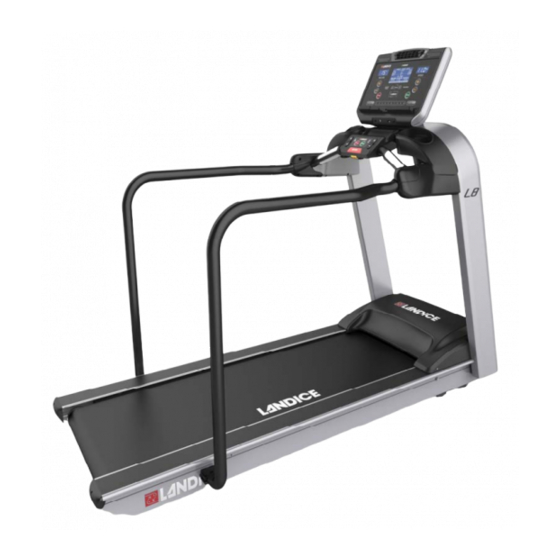
1. Introduction Your Landice treadmill is a high-quality fitness tool that will provide many years of fitness benefits. Unpleasant weather is no longer an obstacle to getting your exercise. Cold, windy, wet days will never discourage you again, nor will heat and humidity. - Page 12 Introduction Figure 1-1. Treadmill Features and Controls Control Panel Fan Vent Fan Controls USB Port Reading Rack Bottle Holder Accessory Tray Pulse Grip Pulse Grip Speed Adjust Incline Emergency Adjust Stop Button Resume Stop Button Safety Lanyard Block Table 1-1 Treadmill Features and Controls Item Description Control Panel...
- Page 13 Introduction Table 1-1 Treadmill Features and Controls (Continued) Item Description USB Port Provides a charging port for most devices up to 600mA. Service use only: allows treadmill software to be updated. Reading Rack Holds reading material or tablet. Accessory Tray Provides accessory storage.
-
Page 14: Heart Rate Monitoring
Introduction 1.2. Heart Rate Monitoring This section provides basic concepts of heart rate monitoring so you can better understand how to use it to reach the fitness level you desire. 1.2.1. What is exercise intensity? Exercise intensity is simply a measure of how hard you are working at a given time during exercise. -
Page 15: Why Should I Monitor Exercise Intensity
Introduction If John is 35 years old, what is his estimated maximum heart rate? John’s estimated maximum heart rate is: 220 - 35 = 185 185 beats per minute is the estimated maximum number of times John’s heart can beat before his body would fatigue or “max out.”... -
Page 16: How Do I Determine My Target Heart Rate Zone
Introduction 1.2.4. How do I determine my Target Heart Rate Zone? Your THRZ represents the minimum and maximum number of times your heart should beat in one minute of exercise. The ACSM recommends that all individuals should work within a Target Heart Rate Zone of 60% to 85% of Maximum Heart Rate. -
Page 17: Wireless Chest Strap Monitoring System
THRZ during workouts. A heart rate monitor provides a reminder of the intensity and quality of each workout session. Landice heart rate monitors are used to monitor your level of exercise intensity during workouts. Pulse meters have a high margin for error. -
Page 18: Contact Heart Rate Monitoring System
Introduction 1.3.2. Contact Heart Rate Monitoring System The Contact Heart Rate Monitoring System is designed for use at walking speeds. A natural running motion involves using your arms to maintain balance. Because the Contact Heart Rate Monitoring System requires your arms to remain stationary, we recommend using the pulse grips at speeds of less than approximately 4 mph (6.4 km/h) or the fastest speed at which you are comfortable walking. -
Page 19: Treadmill Program Capabilities
Introduction 1.4. Treadmill Program Capabilities The treadmill has the following program capabilities: • Built-in Programs: You enter the program’s maximum time, speed and incline. 5 Built-in Programs. See page 45. • User-Defined Programs: A User-Defined Program looks and runs exactly like a Built-In Program. The primary difference between Built-In and User-Defined Programs is customization. - Page 20 Introduction...
-
Page 21: Installation
2. Installation 2.1. Tools Needed • Socket set with 3/8” socket, 1/2” socket, and 9/16” socket • Open end wrenches 14mm and 19mm, or adjustable open end wrench • Hex wrenches: 4mm, 5mm, 6mm • Cross-tip screwdriver • Razor blade knife 2.2. - Page 22 Figure 2-2. Remove box and discard. 4. The L8 treadmill and final assembly components including 90 Series Hardware kit for both models are held together with plastic strapping. Remove these straps using caution as they may be under tension.
- Page 23 Installation Be careful! Straps are under pressure. CAUTION CAUTION To avoid damaging the treadmill, DO NOT cut CAUTION CAUTION through the center of the box. Figure 2-2. Cut Line...
-
Page 24: Assembly
Locate the plastic bag that contains the Owner's Manual and the 90 Series Hardware Kit. • 90 Series Hardware Kit contains: • Handrail screws-12x •... -
Page 25: Medical Rail Installation
Installation 2. Use a 3/8” socket to remove three bolts from each side of the upright bracket on the frame. Slide the upright down over both brackets (Figure 2-3). Upright legs may require slight compression to properly fit between the upright brackets. - Page 26 Installation • 2 Medical rail covers: left and right • 12 Medical rail cover screws, M8x16, found in the 90 Series Hardware Kit • 2- 5/16” bolts to attach Medical Rail to Medical Rail Bracket with 2-5/16" lock washers - found in Medical Rail •...
- Page 27 Installation Figure 2-5. Medical Rail Bolt Medical Rail 5/16” Bolt with Lock Washer (both sides) 3. Attach Medical Rail to Frame (Figure 2-6) using 1/4x20 self-tapping screws with long cross tip screwdriver. Figure 2-6. Medical Rail to Frame Attachment Points 1/4”x20 self- tapping screws 4.
- Page 28 Cap Screw (6x) 6. Begin with left outside cover installation by inserting the (6) M8x16 Socket Head Cap Screws (found in 90 series hardware kit) through the upright mounting bracket into the outside cover corresponding treaded holes. Be certain to start all (6) screws by hand prior to tightening.
-
Page 29: Optional Handrail Installation
1. Using a 4mm hex wrench, remove (3) M5X15 screws from each inner handrail cover. Slide the handrail onto the bracket found on the upright and secure with (6) M8x15 socket head cap screws found in the 90 Series Hardware Kit. Repeat on other side. (Figure 2-10). -
Page 30: Plastic Bridge Installation
Installation Figure 2-10. Optional Handrail Installation Inner Handrail Cover M8X15 (6x) Socket Head M5X15 (3x) Cap Screw Socket Head Cap Screw Handrail Both Sides 2. Install the inner handrail covers on both sides with (3) M5x15 socket head cap screws using the 4mm hex wrench. 2.3.4. - Page 31 Installation Figure 2-11. Plastic Bridge Installation - Upper Screws Plastic Bridge M6X16 (4x) Button Head Cap Screws Notch Cables from Lower Control Panel 2. Attach bridge from underneath with (2) M6x16 button head cap screws from the hardware kit with a 5mm hex wrench. (Figure 2-12).
- Page 32 Installation Figure 2-13. Lower Control Panel Cables Upright Center Hole Ribbon Cable Hole in Plastic Pulse Cable Bridge Guide Wire Tie 4. Engage the tray tabs in the notches of the plastic bridge. Rotate the Accessory Tray as shown to snap the posts into their receivers.
- Page 33 Installation Wire Harness, the flat ribbon cable, and the wireless pulse cable. (Figure 2-15). Figure 2-15. Display Console Cables Wireless Pulse Cable Upper Wire Harness Guide Wire Ribbon Cable 6. Find the wire tie coming from the Upright Center Hole. Wrap the wire tie around the Upper Wire Harness (see Figure 2-15) and feed the connectors into the Upright Center Hole.
- Page 34 Installation Figure 2-16. Upper Wire Harness Routing Path Upright Center Hole Guide Wire 7. Connect the ribbon cable and the pulse cable from the upright center hole to the to the corresponding cables from the Display Console (Figure 2-17). 8. Ensure cables are not crimped or caught between console and upright, then engage the studs on the console in their keyways in the upright then pull forward to lock the Display Console in place.
- Page 35 Installation Figure 2-17. Console Assembly Installation Pulse cable Stud (both sides) Ribbon Cable Upper Wire Harness Keyway (both sides) 9. Remove power cord from motor pan and plug into receptacle at front of treadmill. 10. Run the Upper Wire Harness behind the Elevation Motor (opposite screw end, Figure 2-19) and connect it to the Motor Control Board.
- Page 36 Installation Figure 2-19. Motor Wiring Connections Elevation Motor Drive Motor Motor Control Board 12. Using (4) M6x75 button head cap screws from the 90 Series Hardware Kit and a 5mm hex wrench, secure Display Console assembly to upright. (Figure 2-20). Figure 2-20.
-
Page 37: Leveling Feet
Installation 2.3.5. Leveling Feet 1. Confirm that all treadmill feet are touching the ground. If necessary, loosen the 19mm and 14mm nuts using open end or adjustable wrench, until foot touches the floor. (Figure 2-21). Figure 2-21. Leveling Feet 19mm Jam Nut 14mm Adjustment Nut Increases Height Decreases Height... - Page 38 Installation 4. Lock each leveling foot into place by threading the 19mm nut until it touches the bottom of the frame. Turn the 19mm nut counterclockwise and 14mm nut clockwise using an open end wrench to lock each foot into place. 5.
- Page 39 Installation Figure 2-23. Motor Cover Screw Locations 8-32x1 (4x) Cross-head Screws Do not plug treadmill into a surge suppressor or WARNING GFI outlet. 7. Plug the treadmill power cord into a dedicated power outlet. Ensure that the power cord has plenty of slack and will not be pinched beneath the treadmill as the treadmill elevates up and down.
- Page 40 Installation 11. As you walk, test the treadmill by adjusting speed and incline. Ensure all displays light. 12. The treadbelt is tracked (centered) and tensioned by the take-up screws located at the back of the treadmill (Figure 2-24). If the treadbelt is too loose (slipping as you walk), turn both screws clockwise by 1/4 turn to tighten using the 9/16”...
-
Page 41: Rehab Treadmill Operation
3. Rehab Treadmill Operation 3.1. Rehab Control Panel Table 3-1 Control Panel Functions Function Description INCLINE Displays the incline of the treadmill in percent (%). SPEED Displays the current speed of the treadbelt in MPH (km/hr in metric mode). Powers up the treadmill and lights all displays. STOP Press once to pause the treadmill or twice to turn it off. - Page 42 Rehab Treadmill Operation Table 3-1 Control Panel Functions (Continued) Function Description To use the built-in, user-defined and heart rate workout programs: PROGRAMS Press at any time to display the programs selection screen. Use arrow to scroll through the program ENTER previews and select the desired program by pressing You are then prompted to enter the program’s specific parameters (Maximum Speed, Incline, Time, etc.).
-
Page 43: Display Features
Rehab Treadmill Operation Table 3-1 Control Panel Functions (Continued) Function Description The Express Speed and Express Incline keys, in conjunction with the numeric keypad, allow you to directly enter a target EXPRESS speed or incline without using the (+/–) keys. Press SPEED EXPRESS INCLINE , then enter the desired value... - Page 44 Rehab Treadmill Operation Table 3-2 Display Features Feature Description TIME Time logged on treadmill, displayed as Minutes:Seconds DISTANCE Miles logged on treadmill (kilometers when in metric) PACE Time to complete 1 mile (1 kilometer when in metric) CALORIES Total calories burned, based on entered user weight CALS/HR Approximate calories used per hour, based on user weight 1/4-mile (400 meter in metric) track and Lap Indicator...
-
Page 45: Using The Treadmill
Rehab Treadmill Operation 3.3. Using the Treadmill 1. Make sure you have read and understand this owner’s manual before beginning. 2. Plug the treadmill power cord into its outlet. 3. Straddle the treadbelt with one foot on each traction strip. 4. -
Page 46: Running A Built-In Program
Rehab Treadmill Operation Table 3-3 Built-In Programs Screen Program Description FAT BURN: This program features two elevation peaks along with gradual changes in speed. The overall goal is to raise heart rate, maintain the raised heart rate for most of the workout, then gradually bring heart rate down during the last 2 cool down segments. - Page 47 Rehab Treadmill Operation 3. Select a built-in program by using the arrow to scroll through the list, then press ENTER. You are prompted to enter the following program parameters: • Maximum Speed: This scales the speed curve to the maximum speed entered. •...
-
Page 48: User Programs
Rehab Treadmill Operation 9. Press ENTER or use the arrow keys at any time to view any of the other motivational screens during your program, including the Program Profile screen to see a program overview. When viewing a motivational screen other than the Program Progress Detail screen during a segment change, the display temporarily shows the Program Progress Detail screen then returns to the original screen. -
Page 49: Learn Mode
Rehab Treadmill Operation Note: Pressing ENTER toggles between speed, incline and time values for the current segment. To change segments, press either arrow. You can change segments in either the forward of reverse direction. 5. Use the numeric keypad to change the value and press ENTER. - Page 50 Rehab Treadmill Operation 1. Start a workout, then press PROGRAMS to display the Programs selection screen. 2. Scroll through the program options by pressing PROGRAMS or use the arrow keys. When the USER PROGRAM PREVIEW you desire is shown, press ENTER.The User Program Preview Screen displays the program overview and the total program time.
-
Page 51: Specific Goal Programs
Rehab Treadmill Operation 3.6. Specific Goal Programs The Rehab treadmill provides Specific Goal programs. Whether you want to go for a 3-mile run or simply exercise for 15 minutes, the Goal Progress screen accurately assesses your progress with a variety of statistics. During these programs you retain full manual control. -
Page 52: Heart Rate Control Program
Rehab Treadmill Operation 3.7. Heart Rate Control Program The Rehab treadmill offers a Heart Rate Control (HRC) program that displays your heart rate and automatically varies treadmill speed and elevation. HRC training allows you to maximize your workout performance while minimizing your workout time. -
Page 53: Built-In Hrc Program
Rehab Treadmill Operation 3.7.1. Built-in HRC Program 1. Press PROGRAMS to display the Programs selection screen. Press ENTER while the HR Control program is displayed. 2. Select a program by using the arrow to scroll through the list, then press ENTER. You are prompted to enter the Maximum Speed: This scales the speed curve to... - Page 54 Rehab Treadmill Operation...
-
Page 55: Fitness Testing
4. Fitness Testing 4.1. Introduction The Rehab treadmill has built-in tests that measure fitness level based on your age, gender, and performance. A person’s fitness level can be measured by the amount of oxygen their body can consume while exercising at maximum capacity. - Page 56 Fitness Testing PROGRAMS or use the arrow keys. Select the Balke Fitness Test by pressing ENTER. 2. Use the keypad or arrow to enter your age (10 to 99), then press ENTER or wait 3 seconds. 3. Enter your gender using the center arrow to toggle to MALE or FEMALE.
-
Page 57: Firefighter (Gerkin) Fitness Test
Fitness Testing Table 4-1 Men: VO Rating <20 20-29 30-39 40-49 50-59 60-69 >69 >65 >62 >58 >54 >52 >50 >48 Superior 57-65 54-62 50-58 46-54 44-52 42-50 40-48 Excellent 47-56 44-53 40-49 37-45 35-43 32-41 30-39 Good 37-46 35-43 32-39 28-36 26-34... - Page 58 Fitness Testing Test Parameters • Maximum Speed: 7 mph • Maximum Incline: 15% (cannot be modified) • Maximum Heart Rate: 85% of Maximum Heart Rate (See Heart Rate Monitoring sections). To run the test: 1. Press PROGRAMS to view the programs screen. 2.
- Page 59 Fitness Testing This test increases in difficulty until you reach the target heart rate, then a 30-second countdown follows and ends the test. To stop the test at any time, press any key other than ENTER. Upon completion the treadmill displays a VO Max score and fitness assessment based on your performance compared to the general population.
- Page 60 Fitness Testing...
-
Page 61: Maintenance And Troubleshooting
Under no circumstances should the motor cover be removed except by a Landice factory-authorized technician. 5.2.1. Lubrication In institutional settings, Landice recommends lubricating the underside of the treadbelt with Landice SlipCoat every 3,000 miles. See instructions included with SlipCoat Lubricant. -
Page 62: Treadbelt Tracking Adjustment
Maintenance and Troubleshooting 5.2.2. Treadbelt Tracking Adjustment Note: On the L7 model you should see an equal gap on either side of the treadbelt. On L8 models, a yellow warning label is visible on the deck from the rear of the treadmill when the treadbelt is not tracked correctly. -
Page 63: Motor Drive Belt Tensioning
Maintenance and Troubleshooting 5.2.4. Motor Drive Belt Tensioning Moving parts can cause serious injury. Always WARNING unplug treadmill before placing hands beneath the treadbelt! DO NOT OVER-TIGHTEN. Over-tightening the CAUTION CAUTION motor drive belt can damage the drive motor and front roller. - Page 64 “No Errors Detected”, or “Error Detected, Contact Service Provider”. Contact your Dealer or go to www.landice.com and click on Service Locator to find a provider in your area. To manually enter self- diagnostics mode, with the treadmill off, press the CENTER ARROWS and START at the same time.
-
Page 65: Hidden Menus
Maintenance and Troubleshooting 5.4. Hidden Menus The Hidden Menus provide the ability to control specific settings. To access the Hidden Menus press INCLINE (-), STOP and START at the same time while the control panel is off. This will provide access to the items below. To navigate through the menu use the SPEED or INCLINE (+ or -) keys to move up and down the list. - Page 66 Maintenance and Troubleshooting • Toggle Client Mode: Provides the ability to show two Clients and a guest on home screen. This feature is for residential use only.
- Page 68 111 Canfield Avenue, Suite A-1, Randolph, NJ 07869 1-800-LANDICE Tel. 973-927-9010 · Fax 973-927-0630 www.landice.com...
Need help?
Do you have a question about the 90 Series and is the answer not in the manual?
Questions and answers