
Related Manuals for Advantech PCA-6276


Summary of Contents for Advantech PCA-6276
- Page 1 PCA-6276 Full-size dual Socket 370 Intel ® Celeron™ processor-based PCI/ISA-bus CPU card User's Manual...
-
Page 2: Copyright Notice
Copyright notice This document is copyrighted, 2000, by Advantech Co., Ltd. All rights are reserved. Advantech Co., Ltd. reserves the right to make improvements to the products described in this manual at any time without notice. No part of this manual may be reproduced, copied, translated or transmitted in any form or by any means without the prior written permission of Advantech Co., Ltd. -
Page 3: Technical Support
A Message to the Customer Advantech customer services Each and every Advantech product is built to the most exacting specifications to ensure reliable performance in the harsh and demanding conditions typical of industrial environments. Whether your new Advantech equipment is destined for the laboratory or the... - Page 4 PCA-6276 Series comparison table Model PCA-6276V PCA-6276VE CPU: Dual Intel Celeron Socket 370 System chipset: Intel 440 BX BIOS: Award P&P Flash BIOS L2 cache: 128 KB (on CPU) Max. system RAM: 1 GB (4 x 168-pin DIMM sockets) ISA High Drive: Up to 64 mA...
-
Page 5: Product Warranty
Advantech assumes no liability under the terms of this warranty as a consequence of such events. If an Advantech product is defective, it will be repaired or replaced at no charge during the warranty period. For out-of-warranty repairs, you will be billed according to the cost of replacement materials, service time and freight. -
Page 6: Initial Inspection
It should be free of marks and scratches and in perfect working order upon receipt. As you unpack the PCA-6276, check it for signs of shipping damage. (For example, damaged box, scratches, dents, etc.) If it is damaged or it fails to meet the specifications, notify our service department or your local sales representative immediately. -
Page 7: Table Of Contents
Contents Chapter 1 Hardware Configuration ......1 Introduction ................2 Features ................3 Specifications ..............4 1.3.1 System .................4 1.3.2 Memory ...............4 1.3.3 Input/Output ..............4 1.3.4 VGA interface .............5 1.3.5 Ethernet LAN (PCA-6276VE only) ......5 1.3.6 Industrial features ............5 1.3.7 Mechanical and environmental specifications ....6 Board Layout: Main Features ..........7 Jumpers and Connectors ...........8 Board Layout: Jumper and Connector ...... - Page 8 USB Connector (CN6) .............22 VGA Connector (CN7) ............23 Ethernet Connector (CN8) ..........23 Serial Ports (CN9: COM1; CN10: COM2) ....24 PS/2 Keyboard and Mouse Connector (CN11) .....25 External Keyboard Connector (CN12) ......25 2.10 IR Connector (CN13) ............26 2.11 CPU Fan Connectors (CN14, CN24) ......26 2.12 Front Panel Connectors (CN16, CN17, CN18, CN19 and CN21) ......27 2.12.1 Keyboard lock and power on LED (CN16) ....27...
- Page 9 3.4.11 OS Select for DRAM > 64MB........ 37 3.4.12 Video BIOS Shadow ..........37 3.4.13 C8000-CBFFF Shadow / DC000-DFFFF Shadow .37 Chipset Features Setup ............38 3.5.1 SDRAM RAS to CAS Delay ........38 3.5.2 SDRAM RAS Precharge Time .........38 3.5.3 SDRAM CAS Latency Time ........39 3.5.4 DRAM Data Integrity Mode ........39 3.5.5 16 Bit I/O Recovery Time / 8 Bit I/O Recovery Time ................39...
- Page 10 Chapter 4 SVGA Setup..........47 Before You Begin .............48 Features ................49 Installation ................49 Driver Installation ............50 4.4.1 Necessary prerequisites ..........50 4.4.2 Before you begin ............50 4.4.3 Changing display drivers in Windows ......50 4.4.4 Changing color schemes ...........50 Windows 95/98 Drivers Setup Procedure ......51 Windows NT/98SE Drivers Setup Procedure ....54 Chapter 5 LAN Configuration ........
- Page 11 Appendix A Programming the Watchdog Timer ..79 Programming the Watchdog Timer ....... 80 Appendix B Pin Assignments ........83 Primary (CN1) and Secondary (CN2) IDE Connectors 84 Floppy Drive Connector (CN3) ........85 Parallel Port Connector (CN4) ........86 USB Connector (CN6) .............86 VGA Connector (CN7) ............86 Ethernet 10/100Base-T RJ-45 Connector (CN8) ...88 COM1/COM2 RS-232 Serial Port (CN9, CN10) ...88...
-
Page 12: Chapter 1 Hardware Configuration
Hardware Configuration This chapter gives background informa- tion on the PCA-6276. It then shows you how to configure the card to match your application and prepare it for installation into your PC. Sections include: • Introduction • Features • Specifications •... -
Page 13: Introduction
Introduction The PCA-6276 all-in-one industrial grade CPU card uses two of ® Intel's highly acclaimed Celeron™ processors, together with the Intel 440BX PCI chipset. The card works with standard ISA or PCI/ISA-bus passive backplanes. The CPU provides 128 KB on-CPU L2 cache, eliminating the need for external SRAM chips. -
Page 14: Features
Features ® • Dual Intel Celeron™ Socket 370 architecture ® • Accepts Intel Celeron™ processor up to 500+ MHz ® • Intel 82440BX PCI set, FSB 66/100 MHz ® • Four DIMM sockets to support Intel PC100-compliant SDRAMs up to 1 GB; supports ECC •... -
Page 15: Specifications
• Bus interface: PCI/ISA bus, PICMG compliant • Bus speed: ISA: 8 MHz PCI: 33 MHz • DMA channels: 7 • Interrupt levels: 15 • Enhanced parallel port: Configurable to LPT1, LPT2, LPT3 or disabled. Standard DB-25 female connector provided. Supports EPP/ECP/SPP PCA-6276 User's Manual... -
Page 16: Vga Interface
• Serial ports: Two RS-232 ports with 16C550 UARTs (or compatible) with 16-byte FIFO buffer. Supports speeds up to 115.2 Kbps. Ports can be individually configured to COM1, COM2 or disabled • Keyboard and PS/2 mouse connector: A 6-pin mini-DIN connector is located on the mounting bracket for easy connection to a keyboard or PS/2 mouse. -
Page 17: Mechanical And Environmental Specifications
• Power supply voltage: +5 V, ±12 V • Power consumption: +5 V @ 14 A (max.) ±12 V @ 100 mA (max.) • Board size: 338 x 122 mm (13.3" x 4.8") • Board weight: 0.5 kg (1.2 lb) PCA-6276 User's Manual... -
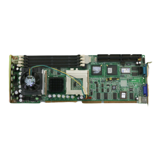
Page 18: Board Layout: Main Features
Board Layout: Main Features Figure 1-1: Board layout: main features Chapter 1 Hardware Configuration... -
Page 19: Jumpers And Connectors
Jumpers and Connectors Connectors on the PCA-6276 board link it to external devices such as hard disk drives and a keyboard. In addition, the board has a number of jumpers used to configure your system for your application. The tables below lists the function of each of the board's jumpers and connectors. - Page 20 Table 1-2: Connectors Label Function Primary IDE connector Secondary IDE connector Floppy drive connector Parallel port USB port VGA connector 10/100Base-T Ethernet connector Serial port: COM1 CN10 Serial port: COM2 CN11 PS/2 keyboard and mouse CN12 External keyboard connector CN13 Infrared (IR) connector CN14 CPU fan connector 1...
-
Page 21: Board Layout: Jumper And Connector
Board Layout: Jumper and Connector Locations Figure 1-2: Board layout: jumper and connector locations PCA-6276 User's Manual... -
Page 22: Safety Precautions
Safety Precautions Warning! Always completely disconnect the power cord from your chassis whenever you work with the hardware. Do not make connections while the power is on. Sensitive electronic components can be damaged by sudden power surges. Only experienced electronics personnel should open the PC chassis. Caution! Always ground yourself to remove any static charge before touching the CPU card. -
Page 23: Jumper Settings
A pair of needle-nose pliers may be useful when setting jumpers. 1.8.2 CMOS clear (J1) The PCA-6276 CPU card contains a jumper that can erase CMOS data and reset the system BIOS information. Normally this jumper should be set with pins 1-2 closed. If you want to reset the CMOS data, set J1 to 2-3 closed for just a few seconds, and then move the jumper back to 1-2 closed. -
Page 24: Watchdog Timer Output (J2)
* default setting 1.8.3 Watchdog timer output (J2) The PCA-6276 contains a watchdog timer that will reset the CPU or send a signal to IRQ11 in the event the CPU stops processing. This feature means the PCA-6276 will recover from a software failure or an EMI problem. -
Page 25: System Memory
(16, 32, 64, 128 or 256 MB) x 1 1.9.1 Sample calculation: DIMM memory capacity Suppose you install a 128 MB DIMM into your PCA-6276's socket 1 and a 32 MB DIMM into sockets 2 and 3. Your total system memory... -
Page 26: Supplementary Information About Dimms
1.9.2 Supplementary information about DIMMs Your PCA-6276 can accept SDRAM memory chips (with or without parity). Also note: • If the PCA-6276 operates at 100 MHz, only use PC100-compliant DIMMs. Most systems will not even boot if non-compliant modules are used. This is due to strict timing issues involved at this speed. -
Page 27: Memory Installation Procedures
Celeron™ processor, you do not have to take care of either SRAM chips or SRAM modules. The built-in second level cache in the Celeron processor yields much higher performance than the external cache memories. The cache size in the Intel Celeron processor is 128 PCA-6276 User's Manual... -
Page 28: Cpu Installation
1.12 CPU Installation ® The PCA-6276 provides a Socket 370 for dual Intel Celeron™ processors. The CPU on the board must have a fan or heat sink attached, to prevent overheating. Warning: Without a fan or heat sink, the CPU will overheat and cause damage to both the CPU and the mother- board. -
Page 29: Dual Processor Systems
1.13 Dual Processor Systems The dual processor function of the PCA-6276 is a special design for ® Socket 370 CPUs. The PCA-6276 supports Intel SMP (Symmetric Multiple Processor) specifications. It is equipped with two PGA 370 sockets with which you can install two Socket 370 processors. Of course, if desired, only one Socket 370 processor need be installed. -
Page 30: Chapter 2 Connecting Peripherals
Connecting Peripherals This chapter tells how to connect periph- erals, switches and indicators to the PCA-6276 board. You can access most of the connectors from the top of the board while it is installed in the chassis. If you have a number of cards installed, or your... -
Page 31: Primary (Cn1) And Secondary (Cn2) Ide Connectors
Connectors You can attach up to four IDE (Integrated Device Electronics) drives to the PCA-6276’s internal controller. The primary (CN1) and secondary (CN2) connectors can each accommodate two drives. Wire number 1 on the cable is red or blue and the other wires are gray. -
Page 32: Floppy Drive Connector (Cn3)
Floppy Drive Connector (CN3) You can attach up to two floppy disk drives to the PCA-6276's on-board controller. You can use any combination of 5.25" (360 KB / 1.2 MB) and/or 3.5" (720 KB / 1.44/2.88 MB) drives. The card comes with a 34-pin daisy-chain drive connector cable. On one end of the cable is a 34-pin flat-cable connector. -
Page 33: Usb Connector (Cn6)
Make sure that wire 1 corresponds to pin 1 of CN4. Pin 1 is on the upper right side of CN4. USB Connector (CN6) The PCA-6276 CPU card provides one USB (Universal Serial Bus) interface, which give complete Plug & Play and hot attach/detach for up to 127 external devices.The USB interface complies with USB Specification Rev. -
Page 34: Vga Connector (Cn7)
VGA Connector (CN7) The PCA-6276V/VE series includes a PCI SVGA interface that can drive conventional CRT displays. CN7 is a standard 15-pin D-SUB connector commonly used for VGA. Pin assignments for CRT connector CN7 are detailed in Appendix B. Ethernet Connector (CN8) Note: Only the PCA-6276VE model includes a 10/100Base-T Ethernet connector. -
Page 35: Serial Ports (Cn9: Com1; Cn10: Com2)
Serial Ports (CN9: COM1; CN10: COM2) The PCA-6276 offers two serial ports, CN9 as COM1 and CN10 as COM2. These ports can connect to serial devices (such as a mouse, printers, and so on) or to a communication network. Table 2-1: Serial port connections (COM1, COM2) -
Page 36: Ps/2 Keyboard And Mouse Connector (Cn11)
PS/2 keyboard connector. External Keyboard Connector (CN12) In addition to the PS/2 mouse/keyboard connector on the PCA-6276's rear plate, there is also an extra on-board external keyboard connector. This gives system integrators greater flexibility in designing their systems. -
Page 37: Ir Connector (Cn13)
These connectors support cooling fans of 500 mA (6 W) or less. The connectors also support hardware monitoring for CPU fan speed. For details on setting up the software for CPU fan speed monitoring, refer to Chapter 6. PCA-6276 User's Manual... -
Page 38: Front Panel Connectors (Cn16, Cn17, Cn18, Cn19 And Cn21)
2.12.2 External speaker (CN17) CN17 is a 4-pin connector for an extenal speaker. If there is no external speaker, the PCA-6276 provides an on-board buzzer as an alternative. To enable the buzzer, set pins 3-4 as closed. 2.12.3 Reset (CN18) Many computer cases offer the convenience of a reset button. -
Page 39: Ide Led (Cn19)
CN21) 2.13.1 ATX feature connector (CN20) and soft power switch connector (CN21) The PCA-6276 can support an advanced soft power switch function if an ATX power supply is used. To enable the soft power switch function: 1. Take the specially designed ATX-to-PS/2 power cable out of the PCA-6276's accessory bag. -
Page 40: Controlling The Soft Power Switch
Warnings: 1. Make sure that you unplug your power supply when adding or removing expansion cards or other system components. Failure to do so may cause severe damage to both your CPU card and expan- sion cards. 2. ATX power supplies may power on if certain motherboard components or connections are touched by metallic objects. - Page 41 PCA-6276 User's Manual...
-
Page 42: Chapter 3 Award Bios Setup
Award BIOS Setup This chapter describes how to set the card’s BIOS configuration data. -
Page 43: Introduction
This type of information is stored in battery-backed RAM so that it retains the setup information when the power is turned off. Entering Setup Press <Del> to enter the setup. Figure 3-1: Award BIOS Setup initial screen PCA-6276 User’s Manual... -
Page 44: Standard Cmos Setup
Standard CMOS Setup Choose the “STANDARD CMOS SETUP” option from the “INITIAL SETUP SCREEN” menu, and the screen below will be displayed. This standard setup menu allows users to configure system components such as date, time, hard disk drive, floppy drive, display, and memory. Figure 3-2: Standard CMOS Setup screen Note: BIOS versions are regularly updated from time to... -
Page 45: Bios Features Setup
The “BIOS FEATURES SETUP” screen appears when choosing the “BIOS FEATURES SETUP” item from the “CMOS SETUP UTILITY” menu. It allows the user to configure the PCA-6276 according to his particular requirements. Below are some major items that are provided in the BIOS FEATURES SETUP screen. -
Page 46: Boot Sequence
3.4.2 Boot Sequence This function determines the sequence in which the computer will search the drives for the disk operating system (i.e. DOS). The BIOS provides the following boot sequences: A,C, SCSI C,A, SCSI (Default) C, CDROM, A CDROM, C, A D, A, SCSI E, A, SCSI F, A, SCSI... -
Page 47: Boot Up Numlock Status
The system will not boot, and access to Setup will be denied if the correct password is not entered at the prompt. Setup The system will boot, but access to Setup will be denied if the correct password is not entered at the prompt. PCA-6276 User’s Manual... -
Page 48: Pci/Vga Palette Snoop
Note: To disable security, select “PASSWORD SETTING” in the main menu. At this point, you will be asked to enter a password. Simply press <Enter> to disable security. When security is disabled, the system will boot, and you can enter Setup freely. 3.4.10 PCI/VGA Palette Snoop Some display cards that are nonstandard VGA, such as graphics accelerators or MPEG Video Cards, may not show colors properly. -
Page 49: Chipset Features Setup
This controls the latency between SDRAM active command and the read/write command. Leave this on the default setting. 3.5.2 SDRAM RAS Precharge Time This controls the idle clocks after issuing a precharge command to SDRAM. Leave this on the default setting. PCA-6276 User’s Manual... -
Page 50: Sdram Cas Latency Time
3.5.3 SDRAM CAS Latency Time This controls the latency between SDRAM read command and the time that the data actually becomes available. Leave this on the default setting. 3.5.4 DRAM Data Integrity Mode “Non-ECC” has byte-wise write capability but no provision for protecting data integrity in the memory module array. -
Page 51: Power Management Setup
“suspend” mode. If the HDD is in a power saving mode, any access to it will wake it up. Note: The HDD will not power down if the Power Management option is disabled. PCA-6276 User’s Manual... -
Page 52: Soft-Off By Pwr-Bttn
3.6.3 Soft-Off by PWR-BTTN If you choose “Instant-Off”, then pushing the ATX soft power switch button once will switch the system to “system off” power mode. You can choose “Delay 4 sec.” If you do, then pushing the button for more than 4 seconds will turn off the system, whereas pushing the button momentarily (for less than 4 seconds) will switch the system to “suspend”... -
Page 53: Dma-X Assigned To : Pci/Isa Pnp
These default values are loaded automatically if the stored record created by the setup program becomes corrupted (and therefore unusable). Load Setup Defaults “LOAD SETUP DEFAULTS” loads the values required by the system for maximum performance. PCA-6276 User’s Manual... -
Page 54: Integrated Peripherals
3.10 Integrated Peripherals Figure 3-7: Integrated peripherals 3.10.1 IDE HDD Block Mode If you enable IDE HDD Block Mode, the enhanced IDE driver will be enabled. Leave IDE HDD Block Mode on the default setting. 3.10.2 IDE Primary Master/Slave PIO/UDMA Mode, IDE Secondary Master/Slave PIO/UDMA Mode (Auto) Each channel (Primary and Secondary) has both a master and a slave,... -
Page 55: Onboard Fdc Controller
This selection is available only if you select “ECP” or “ECP + EPP” in the Parallel Port Mode field. In ECP Mode Use DMA, you can select DMA channel 1, DMA channel 3, or Disable. Leave this field on the default setting. PCA-6276 User’s Manual... -
Page 56: Password Setting
3.11 Password Setting To change the password: 1. Choose the “PASSWORD SETTING” option from the Setup main menu and press <Enter>. The screen will display the following message: Enter Password: Press <Enter>. 2. If the CMOS is good or if this option has been used to change the default password, the user is asked for the password stored in the CMOS. -
Page 57: Save & Exit Setup
This record is required for the system to operate. 3.14 Exit Without Saving Selecting this option and pressing <Enter> lets you exit the setup program without recording any new values or changing old ones. PCA-6276 User’s Manual... -
Page 58: Chapter 4 Svga Setup
SVGA Setup The PCA-6276 features an onboard AGP/VGA interface. This chapter provides instructions for installing and operating the software drivers on the display driver utility CDs included in your PCA-6276 package. -
Page 59: Before You Begin
The enhanced display drivers for the PCA-6276 board are located on the software utility CDs. You must install the drivers and utility software by using the supplied SETUP program for DOS drivers. -
Page 60: Features
Features • Built-in ATI Rage XL 128-bit 3D multimedia accelerator • Supports AGP 2x (133 MHz) mode with sideband addressing and AGP texturing • PC 98 compliant • Superior 3D performance achieved through a floating print setup engine rated at 1.2 million triangles/sec •... -
Page 61: Driver Installation
To change the color scheme, select the Control Panel from the Main window. Select the Color icon. You will be shown the current color scheme. Choose a new color scheme, and click the OK button. PCA-6276 User's Manual... -
Page 62: Windows 95/98 Drivers Setup Procedure
Windows 95/98 Drivers Setup Procedure 1. Insert the utility CD into drive D:. Navigate to Pca6276\Vga\Win9x\Setup. Double-click on "Setup". 2. In the "Severe" window, click on "OK". Chapter 4 SVGA Setup... - Page 63 3. In the "Question" window, click on "Yes". 4. In the "Welcome" window, click on "Next". PCA-6276 User's Manual...
- Page 64 5. In the "Software License Agreement" window, carefully read the "End User License Agreement". If you accept all the terms of this Agreement, click on "Yes". 6. In the "Setup Complete" window, select "Yes, I want to ...". Then click on "Finish". Chapter 4 SVGA Setup...
-
Page 65: Windows Nt/98Se Drivers Setup Procedure
Windows NT/98SE Drivers Setup Procedure 1. Insert the utility CD into drive D:. Navigate to Pca6276\Vga\WinNT\Setup. Double-click on "Setup". 2. In the "Welcome" window, click on "Next". PCA-6276 User's Manual... - Page 66 3. When the "Software License Agreement" window, carefully read the "End User License Agreement". If you accept all the terms of this Agreement, click on "Yes". 4. In the "Select Components" window, click on "Express: Recom- mended". Chapter 4 SVGA Setup...
- Page 67 5. In the "Setup Complete" window, select "Yes, I want to ...". Then click on "Finish". PCA-6276 User's Manual...
-
Page 68: Chapter 5 Lan Configuration
LAN Configuration The PCA-6276VE features an onboard LAN interface. This chapter gives detailed information on Ethernet configu- ration. It shows you how to configure the card to match your application require- ments. -
Page 69: Introduction
• 32-bit Bus Master technology complies with PCI Rev. 2.1 • Plug and Play • Enhancements on ACPI & APM • Complies with PCI Bus Power Management Interface Rev. 1.0, ACPI Rev. 1.0, and Device Class Power Management Rev. 1.0 PCA-6276 User's Manual... -
Page 70: Driver Installation
5.3 Driver Installation The PCA-6276VE's onboard Ethernet interface supports all major network operating systems. The BIOS automatically detects the LAN while booting, and assigns an IRQ level and I/O address. No jumpers or switches are required for user configuration. The drivers and installation instructions are located in the following directories of the utility diskette or CD: •... - Page 71 PCA-6276 User's Manual...
-
Page 72: Chapter 6 Onboard Security Setup
Onboard Security Setup This chapter explains OBS concepts and provides instructions for installing the relevant software drivers. This is done using the OBS driver utility CDs included in your PCA-6276 package. -
Page 73: Introduction
Introduction On-board security (OBS) functions monitor key hardware. They help you maintain your system's stability and durability. The PCA-6276 can monitor 5 sets of system positive voltages, 2 sets of system negative voltages, CPU cooling fan speed, and CPU temperature. -
Page 74: Driver Installation
Driver Installation 6.2.1 Necessary prerequisites The instructions in this manual assume that you understand elementary concepts of MS-DOS and the IBM personal computer. Before installing any driver or utility, you should know how to copy files from a floppy disk to a directory on the hard disk, understand the MS-DOS directory structure, and know how to format a floppy disk. -
Page 75: Windows 95/98/98Se Drivers Setup Procedure
Pca6276\Obs\Win9x\Setup. Double-click on "Setup". Note: If you are using Windows 95, you will have to restart Windows twice. This is necessary to update some outmoded files which are on your system. 2. In the "HWDoctor Setup" screen, click on "OK". PCA-6276 User's Manual... - Page 76 3. In the following "HWDoctor Setup" screen, click on the button indicated. 4. In the following "HWDoctor Setup" screen, click on "OK". Chapter 6 On-board Security Setup...
- Page 77 5. Using the "Start" button, select "Programs". Then click on "HWDoctor". PCA-6276 User's Manual...
- Page 78 6. It is recommended that you load all the default values for all the OBS settings. If desired, however, you can set new conditions for voltage, fan speed and temperature. Chapter 6 On-board Security Setup...
- Page 79 7. "OBS Hardware Monitor" will show an icon on the right side of the bottom window bar. This icon is the "Terminate and Stay Resident" (TSR) icon. It will permanently remain in the bottom window bar, and will activate warning signals when triggered by the onboard security system. PCA-6276 User's Manual...
- Page 80 8. In the "OBS Hardware Monitor" window, click on "Configura- tion" in the top menu bar (see step 6 on page 67). Then click on "Monitoring Config." While enabling each OBS function, you can choose "Faults 1". This will result in a warning message being delivered as soon as any monitored reading exceeds safe limits for the first time.
- Page 81 9. After completing the setup, all the OBS functions are permanently enabled. When a monitored reading exceeds safe limits, a warning message will be displayed and an error beep tone will activate to attract your attention. PCA-6276 User's Manual...
-
Page 82: Windows Nt Drivers Setup Procedure
Windows NT Drivers Setup Procedure 1. Insert the utility CD into drive D:. Navigate to: Pca6276\Obs\Win NT\Hd6276. Double-click on "Hd6276". 2. In the "OBS Hardware Doctor Installation" window, click on "Next". Chapter 6 On-board Security Setup... - Page 83 3. In the following "OBS Hardware Doctor Installation" window, click on "Next". 4. In the following "OBS Hardware Doctor Installation" window, click on "Next". PCA-6276 User's Manual...
- Page 84 5. In the following "OBS Hardware Doctor Installation" window, click on "Finish". 6. In the "Install" window, click on "OK". Chapter 6 On-board Security Setup...
- Page 85 7. Using the "Start" button, select "Programs". Then click on "HWDoctor". PCA-6276 User's Manual...
- Page 86 8. It is recommended that you load all the default values for all the OBS settings. If desired, however, you can set new conditions for voltage, fan speed and temperature. Chapter 6 On-board Security Setup...
- Page 87 9. "OBS Hardware Monitor" will show an icon on the right side of the bottom window bar. This icon is the "Terminate and Stay Resident" (TSR) icon. It will permanently remain in the bottom window bar, and will activate warning signals when triggered by the onboard security system. PCA-6276 User's Manual...
- Page 88 10. In the "OBS Hardware Monitor" window, click on "Configura- tion" in the top menu bar (see step 6 on page 67). Then click on "Monitoring Config." While enabling each OBS function, you can choose "Faults 1". This will result in a warning message being delivered as soon as any monitored reading exceeds safe limits for the first time.
- Page 89 11. After completing the setup, all the OBS functions are permanently enabled. When a monitored reading exceeds safe limits, a warning message will be displayed and an error beep tone will activate to attract your attention. PCA-6276 User's Manual...
-
Page 90: Appendix A Programming The Watchdog Timer
Programming the Watchdog Timer The PCA-6276 is equipped with a watchdog timer that resets the CPU or generates an interrupt if processing comes to a standstill for any reason. This feature ensures system reliability in industrial standalone or unmanned environments. -
Page 91: Programming The Watchdog Timer
The value range is from 01 (hex) to 3F (hex), and the related time interval is 1 sec. to 63 sec. Data Time Interval 1 sec. 2 sec. 3 sec. 4 sec. • • • • • • 63 sec. PCA-6276 User's Manual... - Page 92 After data entry, your program must refresh the watchdog timer by rewriting I/O port 443 (hex) while simultaneously setting it. When you want to disable the watchdog timer, your program should read I/O port 443 (hex). The following example shows how you might program the watchdog timer in BASIC: Watchdog timer example program OUT &H443, data REM...
- Page 93 PCA-6276 User's Manual...
-
Page 94: Appendix B Pin Assignments
Pin Assignments This appendix contains information of a detailed or specialized nature. It includes: • Primary (CN1) and Secondary (CN2) IDE Connectors • Floppy Drive Connector • Parallel Port Connector • USB Connector • VGA Connector • Ethernet 10/100Base-T RJ-45 Connector •... -
Page 95: Primary (Cn1) And Secondary (Cn2) Ide Connectors
DATA 0 DATA 15 SIGNAL GND DISK DMA REQUEST IO WRITE IO READ IO CHANNEL READY HDACKO* IRQ14 ADDR 1 ADDR 0 ADDR 2 HARD DISK SELECT 0* HARD DISK SELECT 1* IDE ACTIVE* * low active PCA-6276 User's Manual... -
Page 96: Floppy Drive Connector (Cn3)
B.2 Floppy Drive Connector (CN3) Table B-2: Floppy drive connector (CN3) Signal Signal FDHDIN* FDEDIN* INDEX* MOTOR 0* DRIVE SELECT 1* DRIVE SELECT 0* MOTOR 1* DIRECTION* STEP* WRITE DATA* WRITE GATE* TRACK 0* WRITE PROTECT* READ DATA* HEAD SELECT* DISK CHANGE* * low active Appendix B Pin Assignments... -
Page 97: Parallel Port Connector (Cn4)
B.3 Parallel Port Connector (CN4) Table B-3: Parallel port connector (CN4) Signal Signal STROBE* AUTOFD* INIT* SLCTINI* ACK* BUSY SLCT * low active PCA-6276 User's Manual... -
Page 98: Usb Connector (Cn6)
B.4 USB Connector (CN6) Table B-4: USB1/USB2 connector (CN6) USB1 Signal USB2 Signal +5 V +5 V Chassis GND B.5 VGA Connector (CN7) Table B-5: VGA connector (CN7) Signal Signal GREEN BLUE H-SYNC V-SYNC Appendix B Pin Assignments... -
Page 99: Ethernet 10/100Base-T Rj-45 Connector (Cn8)
B.6 Ethernet 10/100Base-T RJ-45 Connector (CN8) Table B-6: Ethernet 10/100Base-T RJ-45 connector (CN8) Signal XMT+ XMT- RCV+ RCV- B.7 COM1/COM2 RS-232 Serial Port (CN9, CN10) Table B-7: COM1/COM2 RS-232 serial port (CN9, CN10) Signal PCA-6276 User's Manual... -
Page 100: Ps/2 Keyboard And Mouse Connector (Cn11)
B.8 PS/2 Keyboard and Mouse Connector (CN11) Table B-8: Keyboard and mouse connector (CN11) Signal KB DATA MS DATA KB CLOCK MS CLOCK B.9 External Keyboard Connector (CN12) Table B-9: External keyboard connector (CN12) Signal DATA Appendix B Pin Assignments... -
Page 101: Ir Connector (Cn13)
B.10 IR Connector (CN13) Table B-10: IR connector (CN13) Signal Signal +5 V FIRRX CIRRX IR_RX +5VSB IR_TX B.11 CPU Fan Power Connectors (CN14, CN24) Table B-11: CPU fan power connectors (CN14, CN24) Signal +12 V Detect PCA-6276 User's Manual... -
Page 102: Power Led And Keylock Connector (Cn16)
B.12 Power LED and Keylock Connector (CN16) You can use an LED to indicate when the CPU card is on. Pin 1 of CN16 supplies the LED's power, and Pin 3 is the ground. You can use a switch (or a lock) to disable the keyboard so that the PC will not respond to any input. -
Page 103: Reset Connector (Cn18)
B.14 Reset Connector (CN18) Table B-14: Reset connector (CN18) Signal RESETIN B.15 HDD LED Connector (CN19) Table B-15: HDD LED connector (CN19) Signal (LED+) LED0 (LED-) B.16 ATX Feature Connector (CN20) Table B-16: ATX feature connector (CN20) Signal PS-ON PCA-6276 User's Manual... -
Page 104: System I/O Ports
B.17 System I/O Ports Table B-17: System I/O ports Addr. range (Hex) Device 000-01F DMA controller 020-021 Interrupt controller 1, master 022-023 Chipset address 040-05F 8254 timer 060-06F 8042 (keyboard controller) 070-07F Real-time clock, non-maskable interrupt (NMI) mask 080-09F DMA page register 0A0-0BF Interrupt controller 2 0C0-0DF... -
Page 105: Dma Channel Assignments
IRQ12 PS/2 mouse IRQ13 INT from co-processor IRQ14 Fixed disk controller IRQ15 Available IRQ3 Serial communication port 2 IRQ4 Serial communication port 1 IRQ5 Parallel port 2 IRQ6 Diskette controller (FDC) IRQ7 Parallel port 1 (print port) PCA-6276 User's Manual... -
Page 106: 1St Mb Memory Map
B.20 1st MB Memory Map Table B-20: 1st MB memory map Addr. range (Hex) Device F0000h - FFFFFh System ROM C8000h - EFFFFh Unused C0000h - C7FFFh VGA BIOS B8000h - BFFFFh CGA/EGA/VGA text B0000h - B7FFFh Unused A0000h - AFFFFh EGA/VGA graphics 00000h - 9FFFFh Base memory... - Page 107 PCA-6276 User's Manual...
Need help?
Do you have a question about the PCA-6276 and is the answer not in the manual?
Questions and answers