
Subscribe to Our Youtube Channel
Related Manuals for Advantech PCA-6277-B


Summary of Contents for Advantech PCA-6277-B
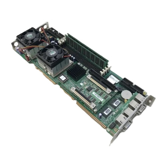
- Page 1 PCA-6277-B Full-size dual socket 370 Intel Pentium III proces- ® ® sor based PCI/ISA-bus CPU card...
- Page 2 Copyright notice This document is copyrighted, 2004, by Advantech Co., Ltd. All rights are reserved. Advantech Co., Ltd. reserves the right to make improve- ments to the products described in this manual at any time without notice. No part of this manual may be reproduced, copied, translated or trans- mitted in any form or by any means without the prior written permission of Advantech Co., Ltd.
- Page 3 A Message to the Customer Advantech customer services Each and every Advantech product is built to the most exacting specifications to ensure reliable performance in the harsh and demanding conditions typical of industrial environments. Whether your new Advantech equipment is destined for the laboratory or the...
- Page 5 Advantech assumes no liability under the terms of this warranty as a consequence of such events. If an Advantech product is defective, it will be repaired or replaced at no charge during the warranty period. For out-of-warranty repairs, you will be billed according to the cost of replacement materials, service time and freight.
- Page 6 It should be free of marks and scratches and in perfect working order upon receipt. As you unpack the PCA-6277-B, check it for signs of shipping damage. (For example, damaged box, scratches, dents, etc.) If it is damaged or it fails to meet the specifications, notify our service department or your lo- cal sales representative immediately.
-
Page 7: Table Of Contents
Contents Chapter 1 Hardware Configuration ......1 Introduction ................2 Features ................3 Specifications ..............5 1.3.1 System .................5 1.3.2 Memory ...............5 1.3.3 Input/Output ..............6 1.3.4 VGA interface .............6 1.3.5 SCSI interface .............6 1.3.6 Ethernet LAN ..............6 1.3.7 Industrial features ............7 1.3.8 Mechanical and environmental specifications ....7 Jumpers and Connectors ...........8 Board Layout: Jumper and Connector Locations .. - Page 8 Floppy Drive Connector (CN3) ........25 Parallel Port (CN4) ............26 USB Port (CN6) ..............27 USB Ports (CN31 and CN32) ..........27 VGA Connector (CN7) .............28 10/100Base-T Ethernet Connectors (CN8 and CN34) ...28 Serial Ports (CN9: COM1; CN10: COM2) ....29 2.10 PS/2 Keyboard & Mouse Connectors (CN11, CN33) ..31 2.11 External Keyboard Connector (CN12) ......31 2.12 CPU_1 Fan Connector (CN14)........32 2.13 CPU_2 Fan Connector (CN15)........32...
- Page 9 3.4.9 Typematic Rate Setting ..........42 3.4.10 Typematic Rate (Chars/Sec) ........42 3.4.11 Typematic Delay (msec) .......... 42 3.4.12 Security Option ............42 3.4.13 MPS Version Control For OS [1.1] ......42 3.4.14 OS Select for DRAM > 64MB ........ 42 3.4.15 Video BIOS Shadow ..........43 Advanced Chipset Features ..........43 3.5.1 DRAM Clock ............44 3.5.2 SDRAM Cycle Length ..........44...
- Page 10 3.6.6 Onboard FDD Controller ..........50 3.6.7 Onboard Serial Port 1 (3F8/IRQ4) ......50 3.6.8 Onboard Serial Port 2 (2F8/IRQ3) ......50 3.6.9 UART 2 Mode ............50 3.6.10 Onboard Parallel Port (378/IRQ7) ......51 3.6.11 Onboard Parallel Mode (ECP + EPP) .....51 3.6.12 ECP Mode Use DMA ..........51 3.6.13 Parallel Port EPP Type ..........51 Power Management Setup ..........52 3.7.1 Power Supply Type ...........52...
- Page 11 3.10.1 Current CPU_1 Temperature ........59 3.10.2 Current CPU_2 Temperature ........59 3.10.3 Current CPUFAN1 Speed ........60 3.10.4 Current CPUFAN2 Speed ........60 3.10.5 CPU_1 VCORE ............60 3.10.6 CPU_2 VCORE ............60 3.10.7 +3.3V/+5V/+12V ............60 3.11 Load Setup Defaults ............61 3.12 Password Setting ..............61 3.13 Save &...
- Page 12 Terminating the SCSI Bus ..........96 Configuring the SCSI interface with SCSISelect ..97 Starting SCSISelect ............99 Using SCSISelect Settings ..........100 Using SCSI Disk Utilities ..........104 Installation under Windows NT/Windows 2000 ..104 7.10 Windows NT Driver Setup Procedure ......105 7.11 Windows 2000 Driver Setup Procedure .......108 Chapter 8 IDE Driver Setup ........115 Installation ..............
- Page 13 B.18 ATX Soft Power Switch (CN21) ........136 B.20 Extension I/O Board Connector (CN28) ......137 B.21 SM Bus Connector (CN29) ..........138 B.22 PS/2 Mouse Connector (CN33) ........138 B.23 System I/O Ports .............139 B.24 DMA Channel Assignments .......... 140 B.25 Interrupt Assignments ...........140 B.26 1st MB Memory Map .............141 B.27 PCI Bus Map ..............
- Page 14 Tables Table 1-1: Jumpers ......................8 Table 1-2: Connectors ....................... 9 Table 1-3: CMOS clear (J1) .................... 16 Table 1-4: Watchdog timer output (J2) ................16 Table 1-5: DIMM module allocation table ............... 17 Table 1-6: DIMM memory capacity sample calculation ..........17 Table 2-1: Serial port connections (COM1, COM2) ............
- Page 15 Figures Figure 1-1: Board layout: jumper and connecter locations ......... 11 Figure 1-2: SCSI daughter board layout ..............12 Figure 1-3: Extension I/O daughter board ..............13...
-
Page 16: Chapter 1 Hardware Configuration
Hardware Configuration This chapter provides background information on the PCA-6277-B. It will show you how to configure the card to match your application and prepare it for installation into your PC.. Sections include: • Introduction • Features • Specifications • Board Layout •... -
Page 17: Introduction
Introduction The PCA-6277-B Series all-in-one industrial grade dual CPU card uses Intel's highly acclaimed Pentium III processor, together with the ® VIA Apollo Pro133A chipset. The card works with standard ISA or PCI/ISA-bus passive backplanes. The CPU provides 256/512 KB on-CPU L2 cache, eliminating the need for external SRAM chips. -
Page 18: Features
A remote monitoring interface is reserved for remote management through Ethernet by using Advantech's SNMP-1000 system management module. 2. Fan status monitoring and alarm: To prevent system overheat- ing and damage, the CPU fan can be monitored for speed and failure. - Page 19 CMOS RAM is automatically backed up to the Flash ROM. This is particularly useful in industrial environ- ments which may cause soft errors. Upon such an error occurring, BIOS will check the data, and automatically restore the original data for booting. PCA-6277-B User's Manual...
-
Page 20: Specifications
Specifications 1.3.1 System • CPU:Dual Intel Pentium III processor, up to 1.4GHz, FSB 100/ ® 133 MHz • BIOS: Award Flash BIOS, 2 Mb • System Chipset: VIA Apollo Pro133A (VT82C694T + VT82C686B) • Green function: Supports power management operation via BIOS. Activated by keyboard or mouse activity •... -
Page 21: Input/Output
• Display memory: 32 MB VRAM 1.3.5 SCSI interface • SCSI: Supports dual-channel ultra 160 SCSI up to 160 MB/sec. • Chipset: Adaptec AIC-7899 1.3.6 Ethernet LAN • Supports dual 10/100Base-T Ethernet networking • Chipset: Realtek 8139C PCA-6277-B User's Manual... -
Page 22: Industrial Features
1.3.7 Industrial features • Watchdog timer: Can generate a system reset or IRQ11. The watchdog timer is programmable, with each unit equal to one second (63 levels). The program uses I/O port hex 443h to control the watchdog timer 1.3.8 Mechanical and environmental specifications •... -
Page 23: Jumpers And Connectors
Jumpers and Connectors Connectors on the PCA-6277-B board link it to external devices such as hard disk drives and a keyboard. In addition, the board has a number of jumpers used to configure your system for your applica- tion. The tables below list the function of each of the board jumpers and connectors. -
Page 24: Table 1-2: Connectors
Table 1-2: Connectors Label Function Primary IDE connector Secodary IDE connector Floppy driver connector Parallel port USB port VGA connector 10/100Base-T Ethernet connector 2 Serial port: COM1 CN10 Serial port: COM2 CN11 PS/2 keyboard and mouse connector CN12 External keyboard connector CN13 Infrared (IR) connector CN14... - Page 25 USB port 0, 1 CN32 USB port 2, 3 CN33 PS/2 mouse connector CN34 10/100Base-T Ethernet connector 1 SCSI Daughter board CN50 68 pin U160 SCSI connector CN51 Ultra Wide SCSI Connector CN52 Ultra Wide SCSI Connector PCA-6277-B User's Manual...
-
Page 26: Board Layout: Jumper And Connector Locations
Board Layout: Jumper and Connector Locations Figure 1-1: Board layout: jumper and connecter locations Chapter 1 Hardware Configuration... - Page 27 CN52 CN51 CN50 Figure 1-2: SCSI daughter board layout PCA-6277-B User's Manual...
- Page 28 Figure 1-3: Extension I/O daughter board Chapter 1 Hardware Configuration...
-
Page 29: Safety Precautions
As a safety precaution, use a grounding wrist strap at all times. Place all electronic components in a static-dissipative surface or static-shielded bag when they are not in the chassis. PCA-6277-B User's Manual... -
Page 30: Jumper Settings
Jumper Settings This section provides instructions on how to configure your card by setting jumpers. It also includes the card's default settings and your options for each jumper. 1.7.1 How to set jumpers You configure your card to match the needs of your application by setting jumpers. -
Page 31: Cmos Clear (J1)
* default setting 1.7.3 Watchdog timer output (J2) The PCA-6277-B contains a watchdog timer that will reset the CPU or send a signal to IRQ11 in the event the CPU stops processing. This feature means the PCA-6277-B will recover from a software failure or an EMI problem. -
Page 32: System Memory
16, 32, 64, 128, 256 or 512 MB. The sockets can be filled in any combination with DIMMs of any size, giving your PCA-6277-B single board computer between 16 MB and 2 GB of memory. Use the following table to calculate the total DRAM memory... -
Page 33: Supplementary Information About Dimms
Your PCA-6277-B can accept SDRAM memory chips (with or without parity). Also note: • If the PCA-6277-B operates at 133/100 MHz, only use PC-133/ PC- 100 compliant DIMMs. Most systems will not even boot if non- compliant modules are used. This is due to strict timing issues involved at this speed. -
Page 34: Memory Installation Procedures
Memory Installation Procedures To install DIMMs, first make sure the two handles of the DIMM socket are in the "open" position. i.e. The handles lean outward. Slowly slide the DIMM module along the plastic guides on both ends of the socket. Then press the DIMM module right down into the socket, until you hear a click. -
Page 35: Cpu Installation
1.11 CPU Installation The PCA-6277-B provides a dual socket 370 for an Intel Pentium ® ® III processor. The CPU on the board must have a fan or heat sink attached, to prevent overheating. Warning: Without a fan or heat sink, the CPU will overheat and cause damage to both the CPU and the motherboard. -
Page 36: Dual Processor Systems
1.12 Dual Processor Systems The dual processor function of the PCA-6277-B is a special design for Socket 370 CPUs. The PCA-6277-B supports Intel SMP (Symmetric ® Multiple Processor) specifications. It is equipped with two PGA 370 sockets with which you can install two Socket 370 processors. Of course, if desired, only one Socket 370 processor need be installed. - Page 37 PCA-6277-B User's Manual...
-
Page 38: Chaper 2 Connecting Peripherals
Connecting Peripherals This chapter tells how to connect periph- erals, switches, and indicators to the PCA-6277-B board. -
Page 39: Introduction
Connectors You can attach up to four IDE (Integrated Drive Electronics) drives to the PCA-6277-B’s built-in controller. The primary (CN1) and secondary (CN2) connectors can each accommodate two drives. Wire number 1 on the cable is red or blue and the other wires are gray. -
Page 40: Floppy Drive Connector (Cn3)
Floppy Drive Connector (CN3) You can attach up to two floppy disk drives to the PCA-6277-B's onboard controller. You can use 3.5" (720 KB and 1.44 MB) drives. The card comes with a 34-pin daisy-chain drive connector cable. On one end of the cable is a 34-pin flat-cable connector. -
Page 41: Parallel Port (Cn4)
The parallel port is normally used to connect the CPU card to a printer. The PCA-6277-B includes an onboard parallel port, accessed through a 26-pin flat-cable connector, CN4. The card comes with an adapter cable which lets you use a traditional DB-25 connector. The cable has a 26- pin connector on one end and a DB-25 connector on the other, mounted on a retaining bracket. -
Page 42: Usb Port (Cn6)
The USB interface can be disabled in the system BIOS setup. USB Ports (CN31 and CN32) The PCA-6277-B provides four ports of USB (Universal Serial Bus) interface, which gives complete Plug & Play and hot swapping for up to 127 external devices.The USB interface complies with USB Specifi- cation Rev. -
Page 43: Vga Connector (Cn7)
VGA Connector (CN7) The PCA-6277-B includes an AGP SVGA interface that can drive conventional CRT displays. CN7 is a standard 15-pin D-SUB connec- tor commonly used for VGA. Pin assignments for CRT connector CN7 are detailed in Appendix B. 10/100Base-T Ethernet Connectors... -
Page 44: Serial Ports (Cn9: Com1; Cn10: Com2)
Serial Ports (CN9: COM1; CN10: COM2) CN10 Chapter 2 Connecting Peripherals... -
Page 45: Table 2-1: Serial Port Connections (Com1, Com2)
The PCA-6277-B offers two serial ports, CN9 as COM1 and CN10 as COM2. These ports can connect to serial devices, such as a mouse or to a communications network. Table 2-1: Serial port connections (COM1, COM2) Connector Ports Address Interrupt... -
Page 46: Ps/2 Keyboard & Mouse Connectors (Cn11, Cn33)
PS/2 keyboard and a PS/2 mouse, respectively. CN11 can also be connected to an adapter cable (P/N: 1700060202, available from Advantech) for connecting to both a PS/2 keyboard and a PS/2 mouse. 2.11 External Keyboard Connector (CN12) -
Page 47: Cpu_1 Fan Connector (Cn14)
This connector supports cooling fans of 2 A or Less 2.14 Front Panel Connectors (CN16, CN17, CN18, CN19, CN21 and CN22) There are several external switches to monitor and control the PCA-6277-B. CN21 CN29 CN18 CN19 CN17 CN16 PCA-6277-B User's Manual... -
Page 48: Keyboard Lock And Power Led (Cn16)
2.14.2 External speaker (CN17) CN17 is a 4-pin connector for an extenal speaker. If there is no external speaker, the PCA-6277-B provides an onboard buzzer as an alternative. To enable the buzzer, set pins 3-4 as closed. Chapter 2 Connecting Peripherals... -
Page 49: Reset (Cn18)
2.14.3 Reset (CN18) Many computer cases offer the convenience of a reset button. Connect the wire from the reset button. 2.14.4 HDD LED (CN19) You can connect an LED to connector CN19 to indicate when the HDD is active. PCA-6277-B User's Manual... -
Page 50: Atx Power Control Connectors (Cn20 And Cn21)
2.15 ATX Power Control Connectors (CN20) CN20 Connect to the CN1 on the Advantech backplane to enable the ATX function, 5V stand-by. 2.16 SNMP-1000 Remote Manager Connector This connector is reserved for Advantech's SNMP-1000 HTTP/SNMP Remote System Manager. The SNMP-1000 allows users to monitor the internal voltages, temperature and fans from a remote computer through an Ethernet network. -
Page 51: Atx Conn (Cn20)& Soft Pwr Switch Conn (Cn21) 35 2.15.2 Controlling The Soft Power Switch
PCA-6277-B User's Manual... -
Page 52: Chapter 3 Award Bios Setup
Award BIOS Setup This chapter describes how to set the card’s BIOS configuration data. -
Page 53: Introduction
"Setup" screen to modify the data. If the "CMOS checksum error..."message appears again and again, please check to see if you need to replace the battery in your system. replace the battery in your system. PCA-6277-B User's Manual... -
Page 54: Entering Setup
Entering Setup Turn on the computer and press <Del>to enter the BIOS setup. Figure 3-1: Award BIOS Setup initial screen Standard CMOS Setup Choose the “Standard CMOS Features” option from the “Initial Setup Screen” menu. This menu allows users to configure system compo- nents such as date, time, HDD, floppy drive, display, and memory. -
Page 55: Advanced Bios Features
The “Advanced BIOS Features” screen appears when choosing the “Advanced BIOS Features” item from the “Initial Setup Screen” menu. It allows the user to configure the PCA-6277-B according to his particular requirements. Below are some major items that are provided in the Advanced BIOS Features screen. -
Page 56: Cpu L2 Cache Ecc Checking
are “Enabled” or “Disabled.” 3.4.3 CPU L2 Cache ECC Checking Enabling allows CPU L2 cache checking. The commands are “Enabled” or “Disabled.” 3.4.4 First/Second/Third/Other Boot Device The BIOS tries to load the OS with the devices in the sequence selected. If the system fail to boot from first, second or third device, the system will seek other bootable device. -
Page 57: Typematic Rate Setting
When security is disabled, the system will boot, and you can enter Setup freely. 3.4.13 MPS Version Control For OS [1.1] 3.4.14 OS Select for DRAM > 64MB This setting allows selecting an OS with greater than 64MB of RAM. PCA-6277-B User's Manual... -
Page 58: Video Bios Shadow
Advanced Chipset Features By choosing the “Advanced Cipset Features” option from the “Initial Setup Screen” menu, the screen below will be displayed. This sample screen contains the manufacturer’s default values for the PCA-6277-B, as shown in Figure 3-5: Note: DRAM default timings have been carefully chosen and should ONLY be changed if data is being lost. -
Page 59: Dram Clock
3.5.3 Bank Interleave This item allows you to select the value in this field, depending on whether the board has paged DRAMs or EDO (extended data output) DRAMs. The Choice: EDO 50ns, EDO 60ns,Slow, Medium, Fast, Turbo. PCA-6277-B User's Manual... -
Page 60: Memory Hole
3.5.4 Memory Hole In order to improve performance, certain space in memory is reserved for ISA cards. This memory must be mapped into the memory space below 16MB. The Choice: 15M-16M, Disabled. 3.5.5 System BIOS Cacheable Selecting Enabled allows caching of the system BIOS ROM at F0000h- FFFFFh, resulting in better system performance. -
Page 61: Onboard Usb
CPU must wait until the write is complete before starting another write cycle. The choice: Enabled, Disabled.. 3.5.14 PCI Dynamic Bursting When Enabled, every write transaction goes to the write buffer. Burstable transactions then burst on the PCI bus and nonburstable transactions don’t. The choice: Enabled, Disabled PCA-6277-B User's Manual... -
Page 62: Pci Master 0 Ws Write
3.5.15 PCI Master 0 WS Write When Enabled, writes to the PCI bus are executed with zero wait states. The choice: Enabled, Disabled 3.5.16 PCI Delay Transaction The chipset has an embedded 32-bit posted write buffer to support delay transactions cycles. Select Enabled to support compliance with PCI specification version 2.1. -
Page 63: Integrated Peripherals
IDE devices possible. Because each IDE device may have a different Mode timing (0, 1, 2, 3, 4), it is necessary for these to be independent. The default setting “Auto” will allow autodetection to ensure optimal performance. PCA-6277-B User's Manual... -
Page 64: Init Display First
Figure 3-7: Integrated peripherals (1) 3.6.3 Init Display First This item allows you to choose which one to activate first, PCI Slot or AGP. The choices: PCI Slot, AGP. 3.6.4 Onboard LAN1/LAN2 Chip These items allow you to enable or disable LAN1 and LAN2. The choice is "Enabled"... -
Page 65: Onboard Fdd Controller
The settings are Auto 3F8/IRQ4, 2F8/IRQ3, 3E8/IRQ4, 2E8/IRQ3, and Disabled for the on-board serial connector. 3.6.9 UART 2 Mode This item allows you to select UART mode. The choices: HPSIR, ASKIR, Standard. Figure 3-8: Integrated peripherals (2) PCA-6277-B User's Manual... -
Page 66: Onboard Parallel Port (378/Irq7)
3.6.10 Onboard Parallel Port (378/IRQ7) This field sets the address of the on-board parallel port connector. You can select either 3BC/IRQ7, 378/IRQ7, 278/IRQ5 or Disabled. If you install an I/O card with a parallel port, make sure there is no conflict in the address assignments. -
Page 67: Power Management Setup
The following screen shows the manufactur- er’s defaults: Figure 3-9: Power managememnt setup screen 3.7.1 Power Supply Type The Choice: AT, ATX 3.7.2 ACPI function This item allows you to enable/disable the Advanced Configuration and Power Management (ACPI). The choice: Enabled, Disabled. PCA-6277-B User's Manual... -
Page 68: Power Management
3.7.3 Power Management This category allows you to select the type (or degree) of power saving and is directly related to the following modes: 1. HDD Power Down 2. Doze Mode 3. Suspend Mode There are four selections for Power Management, three of which have fixed mode settings. -
Page 69: Video Off Option
“Delay 4 sec.” If you do so, then pushing the button for more than 4 seconds will turn off the system, whereas pushing the button momentarily (for less than 4 seconds) will switch the system to “suspend” mode. PCA-6277-B User's Manual... -
Page 70: State After Power Failure
3.7.9 State After Power Failure This field lets you to determine the state that your computer returns after a power failure. If sets to Off, the PC will not boot after a power failure. If sets to On, the PC will restart after a power failure. If sets to Auto, the PC will go back to the previous state before a power failure occurred. -
Page 71: Wake Up Event
When On of HDD & FDD, any activity from one of the listed system peripheral devices wakes up the system. 3.8.4 Power On by LAN This shows you to wake up the system via LAN from the remote host. The Choice: Enable, Disable. PCA-6277-B User's Manual... -
Page 72: Power On By Modem
3.8.5 Power On by Modem When enabled, an input signal on the serial Ring Indicator (RI) line (in other words, an incoming call on the modem) awakens the system from a soft off state. The Choice: Enable, Disable. 3.8.6 Power On by Alarm When enabled, you can set the date and time at which the RTC (real- time clock) alarm awakens the system from Suspend mode. -
Page 73: Pnp/Pci Configurations
The commands here are “Auto” or “manual.” Choosing “manual” requires you to choose resources from each following sub-menu. “Auto” automatically configures all of the boot and Plug and Play devices but you must be using Windows 95 or above. PCA-6277-B User's Manual... -
Page 74: Pci/Vga Palette Snoop
3.9.4 PCI/VGA Palette Snoop This is left at “Disabled” and “Enable..” 3.9.5 Assign IRQ for VGA 3.9.6 Assign IRQ for US13 3.10 PC Health Status Figure 3-12: PC health status screen 3.10.1 Current CPU_1 Temperature This shows you the current CPU_1 temperature. 3.10.2 Current CPU_2 Temperature This shows you the current CPU_2 temperature. -
Page 75: Current Cpufan1 Speed
3.10.4 Current CPUFAN2 Speed This shows you the current CPUFAN2 speed. 3.10.5 CPU_1 VCORE This shows CPU_1 core voltage. 3.10.6 CPU_2 VCORE This shows CPU_2 core voltage. 3.10.7 +3.3V/+5V/+12V This shows you the voltage of +3.3V/ + 5V/ +12V PCA-6277-B User's Manual... -
Page 76: Load Setup Defaults
3.11 Load Setup Defaults “LOAD SETUP DEFAULTS” loads the values required by the system for maximum performance. 3.12 Password Setting To change the password: 1. Choose the “Set Password” option from the “Initial Setup Screen” menu and press <Enter>. The screen will display the following message: Enter Password: Press <Enter>. -
Page 77: Save & Exit Setup
3.13 Save & Exit Setup If you select this and press <Enter>, the values entered in the setup utilities will be recorded in the CMOS memory of the chipset. The microprocessor will check this every time you turn your system on and compare this to what it finds as it checks the system. -
Page 78: Chapter 4 Agp Svga Setup
AGP SVGA Setup The PCA-6277-B features an onboard PCI AGP/VGA interface. This chapter provides instructions for installing and operating the software drivers on the display driver CD included in your package. -
Page 79: Before You Begin
The enhanced display drivers for the PCA-6277-B board are located on the software installa- tion CD. You must install the drivers and utility software by using the supplied SETUP program for DOS drivers. -
Page 80: Vga Installation
• User-friendly installation for Windows 95 and Windows NT • AGP 2.0 interface • Supports 32 MB SDRAM • Integrates superior video features. These include filtered sealing of 720 pixel DVD content, and MPEG-2 motion compensation for software DVD VGA Installation First, insert CD drive. -
Page 81: Agp Installation
AGP Installation First, insert CD drive. Then follow the Icons for your PCA Series model number. Click on AGP Drivers "Auto" for Auto-installation. PCA-6277-B User's Manual... - Page 82 1. In the Setup, click on "next." Chapter 4 PCI SVGA Setup...
- Page 83 2.In the Installation Information, choose turbo mode or standard. Then click on "Next." 3. The installaion is complete click on "Yes" to restart the system. PCA-6277-B User's Manual...
-
Page 84: Chapter 5 Lan Configuration
LAN Configuration The PCA-6277-B features an onboard LAN interface. This chapter gives detailed information on Ethernet configuration. It shows you how to configure the card to match your application requirements. -
Page 85: Introduction
5.1 Introduction The PCA-6277-B features an optional 32-bit 10/100 Mbps Ethernet network interface. This interface supports bus mastering architecture and auto-negotiation features. Therefore standard twisted-pair cabling with RJ-45 connectors for both 10 Mbps and 100 Mbps connections can be used. Extensive driver support for commonly-used network systems is also provided. -
Page 86: Driver Installation
5.3 Driver Installation The PCA-6277-B's onboard Ethernet interface supports all major network operating systems. The BIOS automatically detects the LAN while booting, and assigns an IRQ level and I/O address. No jumpers or switches are required for user configuration. Note: Operating system vendors may post driver updates on their websites. -
Page 87: Windows Nt Drivers Setup Procedure
1. In the "Windows NT" screen, click on "Start" and select "Set- tings". Then click on the "Control Panel" icon to select "Net- work". 2. In the "Network" window, select the "Adapters" tab. Then click on "Add...". PCA-6277-B User's Manual... - Page 88 3. In the "Select Network Adapter" window, click on "Have Disk...". 4. When the "Insert Disk" window appears, insert the utility CD into the CD-ROM drive. The correct file path is: E:\Drv_Lan\RTL8139C\WINNT. When you have the correct file path, click on "OK". Chapter 5 LAN Configuration...
- Page 89 5. In the "Select OEM Option" window, click on "OK". 6. In the "Network Setup Wizard", click on "Next". PCA-6277-B User's Manual...
- Page 90 7. In the "Network Setup Wizard", choose "TCI/IP Protocol" and "NETBEUI Protocol." Then, click on "Next." 8. In the "Network Setup Wizard", click on "Next." Chapter 5 LAN Configuration...
- Page 91 9. In the "Network Setup Wizard", click on "Next." 10. In the "Windows NT Setup" click on "Continue" PCA-6277-B User's Manual...
- Page 92 12. In the "Duplex mod", click "OK" 13. In the "Network" window, select the "Adapters" tab. Under "Network Adapters:", highlight "Realtek RTL8139CA/B/C(8130). PCI Fast Ethernet Ad.". Then click on "Close". Chapter 5 LAN Configuration...
- Page 93 14. In the "Microsoft TCP/IP Properties" window, select the "IP Address" tab. Then select "Specify an IP address". Type in the IP Address and Subnet Mask details. Then click on "OK". 15. In the "Network Settings Change" window, click on "Yes". PCA-6277-B User's Manual...
-
Page 94: Windows 2000 Drivers Setup Procedure
5.5 Windows 2000 Drivers Setup Procedure Note: The CD-ROM drive is designed as "E" throughout this section. 1. In the "Windows 2000" screen, click on " Start" and select " settings". Then click on the " Control Panel" icon to select "system". - Page 95 2. In the " System Properties" window, select the " Device Manag- er". PCA-6277-B User's Manual...
- Page 96 3. In "Device Manager" screen, follow the screen instructions, to click on "Properties". 4. In the following screen, to click on "Update Driver". Chapter 5 LAN Configuration...
- Page 97 5. Click on "Next". 6. Following the highlighted item, and click on "Next". PCA-6277-B User's Manual...
- Page 98 7. Click on "Have Disk". 8. Key in "E:\Drv_Lan\RTL8139c\WIN2000", then click on "OK". Chapter 5 LAN Configuration...
- Page 99 9. To highlight the following item, and click "Next". 10. Click "Next". PCA-6277-B User's Manual...
- Page 100 11. Click "Finish" to complete the installation. Chapter 5 LAN Configuration...
- Page 101 PCA-6277-B User's Manual...
-
Page 102: Chapter 6 Onboard Security Setup
Onboard Security Setup This chapter explains OBS concepts and provides instructions for installing the relevant software drivers. This is done using the driver CD included in your PCA- 6277-B package. -
Page 103: Introduction
Introduction Onboard security (OBS) functions monitor key hardware. They help you maintain your system’s stability and durability. The PCA-6277-B can monitor 5 sets of system positive voltages, 2 sets of system negative voltages, CPU cooling fan speed, and CPU temperature. -
Page 104: Windows 2000 Drivers Setup Procedure
Windows 2000 Drivers Setup Procedure 1. Insert the driver CD into your system’s CD-ROM drive. In a few seconds, the software installation main menu appears, as shown in the following figure. Click on the “WIN 9X” button under the “OBS DRIVERS” heading. Chapter 6 Onboard Security Setup... - Page 105 2. When you will see the following message, make sure you have closed all other programs, then click on “Next.” 3. Click on “Browse” to choose destination folder. Then, click on “Next” PCA-6277-B User's Manual...
- Page 106 4. Select an existing folder. Then, click on “Next” 5. After the setup is completed. You can view OBS setting by running this utility. Chapter 6 Onboard Security Setup...
- Page 107 6. It is recommended that you load the default values for all OBS settings. However, if desired, you can extablish new conditions for voltage, fan speed, and temperature. PCA-6277-B User's Manual...
-
Page 108: Chapter 7 Scsi Setup And Configurations
SCSI Setup and Configurations The PCA-6277-B features an onboard SCSI interface. This chapter provides basic SCSI concepts and instructions for installing the software drivers with the SCSI driver disks/CD included in your package. -
Page 109: Introduction
Introduction The PCA-6277-B is equipped with an Adaptec AIC-7899 single-chip PCI-to-SCSI host adapter which provides a dual channel Ultra 160 multitasking interface between your computer’s PCI bus and SCSI devices (disk drives, CD-ROM drives, scanners, tape backups, removable media drives, etc.). Ultra 160 is a new generation of SCSI technology that expands SCSI performance from 80 MBytes/sec to 160 MBytes/sec. -
Page 110: Scsi Ids
installed in a computer and one or more SCSI devices. SCSI cables are used to connect the devices to the SCSI interface. For the SCSI bus to function properly, a unique SCSI ID must be assigned to the SCSI interface and each SCSI device connected to it, and the SCSI bus must be properly terminated. -
Page 111: Terminating The Scsi Bus
SCSI devices is enable or disabled by setting a swetich on the back of the SCSI device. • The last external Ultra160 or Ultra2 SCSI device must be terminated with an LVD/SE (low voltage differential/single ended) terminator PCA-6277-B User's Manual... -
Page 112: Configuring The Scsi Interface With Scsiselect
plug to ensure that the device will operate at its maximum speed. If you use a different kind of terminator plug, the data I/O rate will decrease. By default, termination on the SCSI controller itself is set to Automatic (the preferred method). We recommend that you do not change this default setting. - Page 113 Display <Ctrl><A> Messages Enabled, Disabled Enabled during BIOS Initialization Extended BIOS Translation for Enabled, Disabled Enabled DOS Drives > 1 GByte Verbose/Silent Mode Verbose, Silent Verbose Host Adapter BIOS Enabled Enabled Disabled : Not Scan Disabled: Scan Bus PCA-6277-B User's Manual...
-
Page 114: Starting Scsiselect
Domain Validation Enabled, Disabled Enabled Support Removable Disks Under Disabled Disabled BIOS as Fixed Disks Boot Only, All Disks BIOS Support for Bootable Enabled, Disabled Enabled CD_ROM BIOS Support for Int 13 Enabled, Disabled Enabled Extensions Setting is valid only if Multiple LUN Support is enabled. Settings are valid only if host adapter BIOS is enabled. -
Page 115: Using Scsiselect Settings
We recommend that you dono t change the default setting. • Boot LUN Number-(Default: 0) Specifies which LUN (Logical Unit Number) to boot from on your boot device. This setting is not valid unless Multiple LUN Support is Enabled PCA-6277-B User's Manual... - Page 116 SCSI Device Configuration SCSI Device Configuration options can be set individually for each connected SCSI device. Note: To configure settings for a SCSI device, you must know it’s SCSI ID (see Using Disk Utilities on page 23.) • Sync Transfer Rate-(Default: 160) Determines the maximum synchronous data transfer rate that the SCSI card supports.
- Page 117 3.1.x, ro Windows 95/98. • Verbose/Silent Mode-(Default: Verbose) When set to Verbose, the SCSI card BIOS displays the host adapter model on the screen during sustem buildup. When set to Silent, the message is not displayed during bootup. PCA-6277-B User's Manual...
- Page 118 • Host Adapter BIOS (Configuration Utility Reserves BIOS Space)-(Default: Enabled) Enables or disables the SCSI card BIOS. • Leave at Enabled to allow the SCSI card BIOS to scan and initialize all SCSI devices. • Set to Disabled: Not scan if the devices on the SCSI bus (for example, CD-ROM drives) are controlled by software drivers and do not need the BIOS, and you do not want the BIOS to scan the SCSI bus.
-
Page 119: Using Scsi Disk Utilities
Please follow these steps: 1. Insert Windows NT/Windows 2000 CD Disk. 2. Press F6 immediately when it displays: “Set up is inspecting your computer’s hardware configuration.” 3. Then it enter SCSI installation. Please insert SCSI driver floppy disk. PCA-6277-B User's Manual... -
Page 120: Windows Nt Driver Setup Procedure
7.10 Windows NT Driver Setup Procedure In the Windows NT screen, click on “Start” and select “Setting.” Then click on the “Control Panel” icon to select “SCSI Adapter.” 2. In the SCSI Adapter, choose “Drivers.” Click on “Add” to install SCSI driver. - Page 121 3. Clickon “Have Disk.” 4. Click on “Browse” to select the drivers. If the SCSI driver is supplied in floppy disk, choose the directory A:1. PCA-6277-B User's Manual...
- Page 122 5. Click the SCSI driver, and then click “OK.” 6. The installation of SCSI Driver is completed. Click on “OK.” Chapter 7 SCSI Setup and Configurations...
-
Page 123: Windows 2000 Driver Setup Procedure
1. In the Windows 2000 screen, click on “Start”, select “Setting” and select “Control Panel”. Click on the “Control Panel” icon and then click on “Add/Remove Hardware”. 2. Click on ““Add/Remove Hardware” to launch “Add/Remove Hardware Wizard”. PCA-6277-B User's Manual... - Page 124 3. Select “Add/Troubleshoot a device”. 4. Windows search for new Plug and Play hardware to install. Chapter 7 SCSI Setup and Configurations...
- Page 125 5. Select “Add a new device”. 6. Select “No, I want to select the hardware from a list”. PCA-6277-B User's Manual...
- Page 126 7. Select “SCSI and RAID controllers”. 8. Click “Have Disk”. Chapter 7 SCSI Setup and Configurations...
- Page 127 9. Click “Browse” to select the driver in floppy. 10. Choose the driver. 11. Click OK. PCA-6277-B User's Manual...
- Page 128 Chapter 7 SCSI Setup and Configurations...
- Page 129 PCA-6277-B User's Manual...
-
Page 130: Chapter 8 Ide Driver Setup
IDE Driver Setup This chapter provides the driver setup procedure for IDE drivers. The IDE driver enables the performance of bus mastering functions on ATA-capable Hard Disk Drives and CD-ROMs. -
Page 131: Installation
Installation First, insert CD drive. Then follow the Icons for your PCA Series model number. Click on the IDE Drivers "Auto" for auto-insstallation. PCA-6277-B User's Manual... - Page 132 1. Click on "Next." Chapter 8 IDE Driver Setup...
- Page 133 2. Choose install, and then click on "Next." PCA-6277-B User's Manual...
- Page 134 3. Click on "Finish" to complete the installation. Chapter 8 IDE Driver Setup...
- Page 135 PCA-6277-B User's Manual...
-
Page 136: Appendix A Programming The Watchdog Timer
Programming the Watchdog Timer The PCA-6277-B is equipped with a watchdog timer that resets the CPU or generates an interrupt if processing comes to a standstill for any reason. This feature ensures system reliability in industrial standalone or unmanned environments. -
Page 137: Programming The Watchdog Timer
The value range is from 01 (hex) to 3F (hex), and the related time interval is 1 sec. to 63 sec. Data Time Interval 1 sec. 2 sec. 3 sec. 4 sec. • • • • • • 63 sec. PCA-6277-B User's Manual... - Page 138 After data entry, your program must refresh the watchdog timer by rewriting I/O port 443 (hex) while simultaneously setting it. When you want to disable the watchdog timer, your program should read I/O port 443 (hex). The following example shows how you might program the watchdog timer in BASIC: Watchdog timer example program OUT &H443, data REM...
- Page 139 PCA-6277-B User's Manual...
-
Page 140: Appendix B Pin Assignments
Pin Assignments This appendix contains information of a detailed or specialized nature. It includes: • IDE Hard Drive Connector • Floppy Drive Connector • Parallel Port Connector • USB Connector • VGA Connector • Ethernet 10/100Base-T RJ-45 Connector • COM1/COM2 RS-232 Serial Port •... -
Page 141: Ide Hard Drive Connector (Cn1, Cn2)
DATA 0 DATA 15 SIGNAL GND DISK DMA REQUEST IO WRITE IO READ IO CHANNEL READY HDACKO* IRQ14 ADDR 1 ADDR 0 ADDR 2 HARD DISK SELECT 0* HARD DISK SELECT 1* IDE ACTIVE* * low active PCA-6277-B User's Manual... -
Page 142: Floppy Drive Connector (Cn3)
B.2 Floppy Drive Connector (CN3) Table B-2: Floppy drive connector (CN3) Signal Signal FDHDIN* FDEDIN* INDEX* MOTOR 0* DRIVE SELECT 1* DRIVE SELECT 0* MOTOR 1* DIRECTION* STEP* WRITE DATA* WRITE GATE* TRACK 0* WRITE PROTECT* READ DATA* HEAD SELECT* DISK CHANGE* * low active Appendix B Pin Assignments... -
Page 143: Parallel Port Connector (Cn4)
B.3 Parallel Port Connector (CN4) Table B-3: Parallel port connector (CN4) Signal Signal STROBE* AUTOFD* INIT* SLCTINI* ACK* BUSY SLCT * low active PCA-6277-B User's Manual... -
Page 144: Usb Connector (Cn6)
B.4 USB Connector (CN6) Table B-4: USB1/USB2 connector (CN6) USB1 Signal USB2 Signal +5 V +5 V Chassis GND B.5 VGA Connector (CN7) Table B-5: VGA connector (CN7) Signal Signal GREEN BLUE H-SYNC V-SYNC Appendix B Pin Assignments... -
Page 145: Ethernet 10/100Base-T Rj-45 Conn (Cn8, Cn34)
B.6 Ethernet 10/100Base-T RJ-45 Connector (CN8, CN34) Table B-6: Ethernet 10/100Base-T RJ-45 connector (CN8, CN34) Signal Signal XMT+ XMT- RCV- RCV+ B.7 COM1/COM2 RS-232 Serial Port (CN9, CN10) Table B-7: COM1/COM2 RS-232 serial port (CN9, CN10) Signal PCA-6277-B User's Manual... -
Page 146: Keyboard And Mouse Connnector (Cn11)
B.8 Keyboard and Mouse Connnector (CN11) Table B-8: Keyboard and mouse connector (CN11) Signal KB DATA MS DATA KB CLOCK MS CLOCK B.9 External Keyboard Connector (CN12) Table B-9: External keyboard connector (CN12) Signal DATA Appendix B Pin Assignments... -
Page 147: Ir Connector (Cn13)
B.10 IR Connector (CN13) Table B-10: IR connector (CN13) Signal +5 V IR_RX IR_TX B.11 CPU_1 Fan Power Connector (CN14) Table B-11: CPU fan power connector (CN14) Signal +12 V Detect PCA-6277-B User's Manual... -
Page 148: Cpu_2 Fan Power Connector (Cn15)
B.12 CPU_2 Fan Power Connector (CN15) Table B-12: CPU fan power connector (CN15) Signal +12 V Detect B.13 Power LED and Keylock Connector (CN16) You can use an LED to indicate when the CPU card is on. Pin 1 of CN16 supplies the LED's power, and Pin 3 is the ground. -
Page 149: External Speaker Connector (Cn17)
The CPU card has its own buzzer. You can also connect it to the external speaker on your computer chassis. Table B-14: External speaker (CN17) Function +5 V Internal buzzer Speaker out B.15 Reset Connector (CN18) Table B-15: Reset connector (CN18) Signal RESET PCA-6277-B User's Manual... -
Page 150: Hdd Led Connector (Cn19)
B.16 HDD LED Connector (CN19) Table B-16: HDD LED connector (CN19) Signal LED0 (LED-) Vcc(LED+) B.17 ATX Feature Connector (CN20) Table B-17: ATX feature connector (CN20) Signal PS-ON Appendix B Pin Assignments... -
Page 151: Extension I/O Board Connector (Cn27)
D+ (USB2) D- (USB0) D- (USB3) Vcc (USB1) D- (USB2) Vcc (USB0) Vcc (USB3) GND (USB1) Vcc (USB2) GND (USB0) GND (USB3) 5VSB GND (USB2) 5VSB D+ (USB1) LINK LED (LAN 2) D+ (USB0) ACTLED (LAN 2) PCA-6277-B User's Manual... -
Page 152: Extension I/O Board Connector (Cn28)
B.20 Extension I/O Board Connector (CN28) Table B-20: Extension I/O board connector (CN28) Signal Signal TXC+ (DVI) TX0+ (DVI) TXC- (DVI) TX0- (DVI) FP_SDAT (DVI) TXD+ (LAN2) FP_SCLK (DVI) H_DEC (DVI) RXIN+ (LAN2) FP_VCC (DVI) TXD- (LAN2) TX2+ (DVI) MS DATA (PS/2 MS) TX2- (DVI) RXIN- (LAN2) TX1+ (DVI) -
Page 153: Sm Bus Connector (Cn29)
B.21 SM Bus Connector (CN29) Table B-21: SM bus connector (CN29) Signal SMB_DATA SMB_CLK B.22 PS/2 Mouse Connector (CN33) Table B-22: PS/2 mouse connector (CN33) Signal MS DATA MS CLOCK PCA-6277-B User's Manual... -
Page 154: System I/O Ports
B.23 System I/O Ports Table B-23: System I/O ports Addr. range (Hex) Device 000-01F DMA controller 020-021 Interrupt controller 1, master 022-023 Chipset address 040-05F 8254 timer 060-06F 8042 (keyboard controller) 070-07F Real-time clock, non-maskable interrupt (NMI) mask 080-09F DMA page register 0A0-0BF Interrupt controller 2 0C0-0DF... -
Page 155: Dma Channel Assignments
IRQ12 PS/2 mouse IRQ13 INT from co-processor IRQ14 Fixed disk controller IRQ15 Available IRQ3 Serial communication port 2 IRQ4 Serial communication port 1 IRQ5 Parallel port 2 IRQ6 Diskette controller (FDC) IRQ7 Parallel port 1 (print port) PCA-6277-B User's Manual... -
Page 156: 1St Mb Memory Map
INT A, B, C, D GNT D Note: In the PCA-6277-B LAN devices use "GNT A" signals via PCI slot 1. Therefore, PCI slot 1 cannot be used for plug-in bus master add-on cards such as SCSI cards or LAN cards. - Page 157 PCA-6277-B User's Manual...
Need help?
Do you have a question about the PCA-6277-B and is the answer not in the manual?
Questions and answers