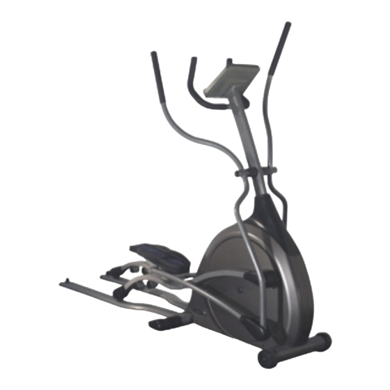
Vision Fitness X6200HRT Assembly Manual
Folding
Hide thumbs
Also See for X6200HRT:
- Owner's manual (56 pages) ,
- Assembly manual (7 pages) ,
- Owner's manual (40 pages)

Related Manuals for Vision Fitness X6200HRT


Summary of Contents for Vision Fitness X6200HRT
- Page 1 A s s e m b l y G u i d e X6200HRT FOLDING ELLIPTICAL TRAINER...
- Page 2 A s s e m b l y G u i d e X6200HRT FOLDING ELLIPTICAL TRAINER To avoid possible damage to this Elliptical Trainer, please follow these assembly steps in the correct order. Before proceeding, find your new Elliptical Trainer’s serial number located on the front axle tube, and enter here: Refer to this number when calling for service, and enter this serial number on your Warranty Card and in your own records.
- Page 3 TOOLS & PARTS INCLUDED Screwdriver Wrench L-Shaped Wrench L-Shaped Wrench PARTS BOX Console Mast Boot, Qty: 1 Dual Action Link Arm Covers, Qty: 2 Dual Action Axle Covers, Qty: 2 Rear Stabilizers, Qty: 2 Pedal Support Bracket, Qty: 2 Water Bottle & Cage, Qty: 1 Heart Rate Chest Strap, Qty:1 Power Supply, Qty: 1 Color-coded Hardware Bags...
- Page 4 HARDWARE INCLUDED BLACK BAG ORANGE BAG M5x10x1T Washer M5x10L Screw M8x20L Screw Quantity: 4 Quantity: 2 Quantity: 1 M8x35x2T Washer Quantity: 2 GREEN BAG M4x10L PanHead Screw M8 Nut Quantity: 4 Quantity: 4 M8x16x1.5T Washer M8x13L Screw Quantity: 2 Quantity: 2 M8x55L Screw Quantity: 2 BLUE BAG...
- Page 5 ORANGE BAG STEP • Slide the axle, with right stabilizer attached, through the right guide rail STEP and through the frame of the product. • Slide the left guide rail onto the left side of the axle. Slide the left stabilizer onto the end of the axle and fix in place with a screw (M8x20L).
- Page 6 PINK BAG STEP • Slide the rubber boot on to the console mast. • Unfold the wire harness located in the frame bracket. Wrap the wire tie coming from the bottom of the console mast around the end of the wire harness.
- Page 7 GREEN BAG STEP • Slide wavy washer (M20x29x1.5t) on the lower link arm axle, which is located under the foot plate. Slide the axle through the bracket located on top of the pedal arm. • Secure the lower link arm in place by attaching the pedal support bracket and screw (M8x13L).
- Page 8 Phillips screwdriver to lock in place. 500 South CP Avenue • P.O. Box 280 • Lake Mills. WI 53551 toll free 1.800.335.4348 • phone 1.920.648.4090 • fax 1.920.648.3373 www.visionfitness.com 2002 Vision Fitness. All Rights Reserved. 9.02 Part #Z62EP34-AG1823PRD AG18.23PRD REV1...
Need help?
Do you have a question about the X6200HRT and is the answer not in the manual?
Questions and answers