Advertisement
Advertisement
Table of Contents

Related Manuals for AnyCubic i3 MEGA


Summary of Contents for AnyCubic i3 MEGA
-
Page 3: Safety Instructions
It is recommended to use protection glasses when cleaning/sanding the printed models to avoid small particles contacting eyes. In case of emergency, immediately turn off the ANYCUBIC 3D printer and contact us or consult for professional advice. Never leave the ANYCUBIC 3D printer unattended during operation.。... - Page 4 Technical Specification Printing Technology: FDM (Fused Deposition Modeling) Build Size: 210×210×205 (mm Layer Resolution: 0.05-0.3 mm Positioning Accuracy: X/Y 0.0125mm,Z 0.002mm Extruder Quantity: Single Nozzle/Filament Diameter: 0.4 mm/1.75mm Print Speed: 20~100mm/s (suggested 60mm/s) Travel Speed: 100mm/s Supported Materials: PLA, ABS, HIPS, Wood Temperature Ambient Operating Temperature: 8°C - 40°C...
-
Page 5: Table Of Contents
Contents 1. Product Overview ........................... 1 2. Part list ............................... 4 3. Assembly instruction ..........................5 4. Leveling ..............................9 4.1 Assisted Leveling ........................... 9 4.2 Manual Leveling .......................... 16 5. Software installation ........................... 19 5.1 Driver installation ........................19 5.2 Cura Installation .......................... - Page 6 Thank you for choosing ANYCUBIC i3 MEGA 3D printer. Please read the assembly instructions carefully. Please visit www.anycubic3d.com for more support information. Email us on support@anycubic3d.com james@anycubic3d.com If you experience any issues with this product, or the performance is not what you had expected, please contact us first before returning the item.
-
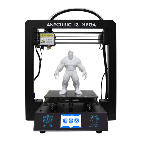
Page 7: Product Overview
1. Product Overview ⑴ ⑹ ⑶ ⑺ ⑿ ⑷ ⑸ ⑻ ⑾ ⑼ ⑵ ⑽ ⒁ ⒂ (22) ⒀ ⒃ (21) ⒇ ⒆ ⒄ ⒅ ⑴Frame ⑵Base ⑶Print head ⑷Z probe ⑸Nozzle ⑹X smooth rods ⑺X end stop ⑻Print platform ⑼Y smooth rods ⑽Filament sensor ⑾Spool holder ⑿Filament spool ⒀Extruder ⒁Z smooth rods ⒂Z lead screw ⒃X motor ⒄Z end stop ⒅Z motors ⒆Y end stop ⒇... - Page 8 Menu Directory Home Menu Print Setup Tools Home menu Print: enter the print menu Setup: enter the setup menu Tools: enter the tools menu (Other information: ①nozzle temperature ②heated bed temperature ③printer status) Print Print: print the selected files in SD card Resume: Resume from outage (only valid for offline print) (Other information: ①Page up and down ②Refresh ③Return to the home menu) Setup...
- Page 9 Motor: Disable all motors (only valid when no print job) Status: Enter the sub-menu with Print/Pause/Resume icon (only valid for offline print) (Other information: ①Files ②Print Rate ③Time ④Progress ⑤E0 Temp ⑥Bed Temp ⑦ coordinates for X/Y/Z axis ⑧Return to previous menu) Speed: Enter the menu to adjust ①Fan speed (0-100) ②Print Rate (50-999) Return: Return to Home Menu Tools...
-
Page 10: Part List
2. Part list Tool pack Screws(M5*8) SD card SD Card reader Gloves Power cord Tweezer Spool holder ANYCUBIC i3 MEGA Test filament (Random) USB cable Backup hotend Scraper Plier... -
Page 11: Assembly Instruction
3. Assembly instruction 1. Unpack and take out the printer and accessories. The smooth rods and lead screw may be greased in factory, so please wear gloves. 2. Find 8 pieces of M5*8mm hex cap screws and the corresponding screw driver. Follow ①... - Page 12 3. Wiring (1) Fig.2, customers are required to select the correct voltage mode according to their local voltage ratings (110V/220V). Please notice that the switch is inside the bottom left of the base and 220V is default. A hex screw driver can be used to move the switch inside. (Figure 2) Choose the voltage ratings (2) There are 3 ports at the bottom right of the base, and accordingly there are 3 cable...
- Page 13 (3) Fig.4, insert “Hotend” connector to the middle port (14 pins). (4) Fig.5, insert “X/Z motors&endstops” connector to the upper port (16 pins). Upper port Convex line Middle port Convex line (Figure 4) (Figure 5) (5) Fig. 6, customers may notice there is a piece of zip tie attached just below the plastic ring of the quick connector.
- Page 14 (Figure 7) (2) Install the filament spool to the spool holder. As shown in Fig.8, pass the filament through the filament sensor. Then, as shown in Fig. 9, insert the filament into the extruder and then into the Teflon tubing (but not fully into the hotend yet). When insert the filament to the sensor and extruder, it is suggested to cut off the bent tip of the filament, and rotate the angle if feels any resistance at the sensor or extruder.
-
Page 15: Leveling
(Figure 9) Load the filament manually 4. Leveling It is essential to have the platform leveled for 3D printing. ANYCUBIC i3 MEGA offers two methods for platform leveling: assisted leveling and manual leveling. For experienced users, it is recommended to just level the platform manually. For new customers, you may use the assisted leveling. - Page 16 Before proceed, make sure the X axis is leveled (Fig. 10), in case X axis lost its balance during shipping or due to other unexpected causes. A rule or maybe caliper or anything with certain length can be used for this measure. The Z lead screw can be turned manually for adjust the levelness of the X axis (wear gloves).
- Page 17 (Figure 11) 3. Tighten the 4 screws/nuts underneath the print platform till stop (Fig. 12), to create a distance between the platform and print head. Click “Tools”-->“Level”, the machine will auto home first and then the X/Y/Z axis will be locked and cannot be moved manually. Next, click “Start” in the pup-up window. (Figure 12) 4.
- Page 18 and finally triggers the sensor and there will be audio feedback from the beeper. When you hear the beep, please stop adjusting the nut and click “Next” for the following point (Fig. 13). Do the same to the rest points. (Figure 13) 5.
- Page 19 If clicking “Check (No-heating)”, the print head will immediately run a rectangular on the print platform, you may observe the distance between the nozzle and platform. Ideally, the distance should be of 0.1~0.2 mm (approx. a paper thin) If clicking “Check (Heating)”(Fig. 15), the machine will automatically heating the nozzle to 200°C and run a rectangular again with extrusion.
- Page 20 Leveling good Too close to the nozzle, you may manually tighten the two nuts at filament evenly extruded to the the left side by ~half-circle. platform. (one circle~0.5mm) (Figure 16) As shown in Fig. 16B, you may need to manually fine tune after assisted leveling to achieve satisfying results.
- Page 21 (Figure 17) As shown in Fig. 18, there might be 3 results for the first layer of the “owl_pair”. Leveled properly Nozzle too close Insufficient extrusion Filament evenly extruded Nozzle too high Poor adhesion (Figure 18) In case of “nozzle too high” or “nozzle too close”(Fig. 18 B & C), please click...
-
Page 22: Manual Leveling
“Stop” on the screen, raise the nozzle to avoid platform burnt (click “Tools”--> “Axis”-->“10”on +Z column), and manually fine tune the nuts under the platform. Specifically, when “nozzle too high”, slowly loosen the corresponding nuts underneath by half circle, while “nozzle too close”, slowly tighten the corresponding nuts underneath by half circle. - Page 23 corresponding nut underneath the platform to let the nozzle and platform become closer until just feel the resistance when dragging the paper in between, (Fig. 19). Likewise, do the same to the rest of 3 corners and the center of the platform. Upon finish, you may refer to Step 8 in last section (Assisted leveling) to try to print the “owl_pair”...
- Page 24 So, turn on the machine, fully tighten the 4 nuts underneath the print platform, and increase the height of print head by clicking “Tools”--> “Axis” --> “10” on +Z column. As shown in Fig. 20, at the right side of X axis, tighten the Z adjustable nut by ~2-3mm (which equals to the thickness of the glass bed).
-
Page 25: Software Installation
“owl pair” to check out the results. 5. Software installation There are two working mode for ANYCUBIC i3 MEGA 3D printer, print offline (SD card) and print online (controlled by PC via USB). Print offline: After leveling the platform, insert SD card, click “Print” at the Home menu and select a file (gcode file) to print. - Page 26 Detailed procedures: right click on “Computer”---> “ Properties ” ---->“Device Manger”, and then follow the images in Fig. 21. Not installed Right click and choose update Find the folder of CP2102 in SD Card Click \Desktop\Mega\ Files_Engish_Mega\Driver_CP2102\win COM3 appears in Ports (Figure 21) After successfully installation, the COMx will appear in the Ports of Device Manager.
-
Page 27: Cura Installation
COMx in Ports, please just uninstall the COMx and try to install the driver again. 5.2 Cura Installation ANYCUBIC i3 MEGA 3D printer reads Gcode file and prints out object layer by layer. Normally we have to change 3D file (such as stl file) into Gcode file for 3D printer to read. - Page 28 (Figure 22) Next, there are few more settings regarding the machine type, show in Fig. 23.
- Page 29 (Figure 23) Upon finish, and run Cura for the first time, there will be a default model, customers may click “File”--->“Clear platform” to delete it. 5.2.1 Load 3D model into Cura (1) Clear the platform by clicking “File”--->“Clear platform” (2) Load 3D files onto the platform by “File” ---> “Load model file…” . Files with extension such as “STL”, “OBJ”, “DAE”...
- Page 30 (4.1) Lay flat: it is very impartant to ensure the flat portion of the model is well attached to the platform. So, please use Lay Flat option everytime after rotating the model, as it will minimize the adhesion issues during printing. (Fig. 24) (4.2) Reset: click it to return the model to the original orientation.
- Page 31 before print starts. Such as the Layers mode: to view the toolpath of the print head to check if there are skipped layers or gaps. Scroll at layers mode (Figure 26) 5.2.3 Cura settings (1) Machine settings Refer to Fig. 27, click “Machine”--->“Machine settings” to input those suggested parameters into the corresponding column.
- Page 32 (2) Basic and Advanced options Suggested parameters of “Basic” and “Advanced” for printing PLA are shown in Fig. 28. Stay the mouse upon each box and there will be explanation for it. (Figure 28) (3) Plugins It is recommended for new user to leave the plugins as default (no plugin enabled). Plugins are custom settings which will active at specific point during printing.
- Page 33 “Pause at height” will allow the printing to pause at a specified height, as well as where the print head would move to and how much filament to retract to prevent extruded filament blobs. So, customers could do filament change during printing. “Tweak at Z”...
- Page 34 to start.gcode. (Figure 30) 5.2.4 Printing by Cura After parameter settings, customer can print online by Cura. Click “File”--->“Print…” enter the printing window. If you have a simplified printing window which is different from that in Fig. 31, please click “File”--->“Preferences…” to choose the ‘Pronterface UI’...
-
Page 35: Printing
temperature would rise and it will start to print when reaching to the target temperature. Use tweezer to carefully get rid of the pre-extruded filament. Check with the COMx or baudrate in “Machine settings” if Cura fails to connect the printer in the “Printing window”. - Page 36 (Figure 32) 2. After pre-heat is finished, please click on Home screen “Tools”-->“Filament”--> “Filament in”(Fig. 33). The extruder motor will work to feed the filament into the hotend. There might be some excessive filament melt through the nozzle, please use tweezer to carefully remove it from the nozzle.
- Page 37 Fig. 35. Never direct scarper to your hands. (Figure 35) ANYCUBIC i3 MEGA 3D printer has a printing sticker which has a lift time about few weeks depends on the usage. Customer may use masking tape as alternative. Tips: ①...
-
Page 38: Manual Filament Change
7. Manual filament change 1. Feed the filament: click via the Home menu: “Tools”--> “Preheat” --> “Preheat PLA (for example)”. After it reaches to the target temperature, press down the handle at the extruder as shown in Fig. 36, and manually push the filament through the Teflon tubing till the hotend and there should be filament melt through the nozzle. -
Page 39: Resume From Outage
8. Resume from outage ANYCUBIC i3 MEGA allows resuming print job after accident power loss. This function only valid when print offline (by SD card only). 1. As shown in Fig. 37, in slicing software (i.e. Cura), it is required to place the model at the rear of platform. - Page 40 2. For the first time of using this function, customers are required to add “G5” to the start.gcode, as shown in Fig. 39. Then, save the model as Gcode file to the SD card by “File”--->“Save GCode…”. Highlight (Figure 39) Type G5 3.
- Page 41 ② It is required not to move the Z axis after power off otherwise resume will be invalid. ③ ANYCUBIC i3 MEGA 3D supports resume from outage only when print offline ④ This function is developed based on Cura. We could not guarantee that this function compatible with other slicing software.
-
Page 42: Trouble Shooting
9. Trouble shooting 1. Motor shaking or abnormal sound ① The corresponding end stop could not be triggered when Home, check the wirings, and inspect any obstacles when manually move the corresponding axis. ② The motor cable are not connected properly, check each connection and then inspect the cable routing for any faults. - Page 43 ③ Check that the bed is leveled and set to a distance of approx. 0.1 mm. ④ Inspect if print mat needs replacement, or use masking tape instead. ⑤ add a brim or raft to the model in slicing software. ⑥...
Need help?
Do you have a question about the i3 MEGA and is the answer not in the manual?
Questions and answers