Advertisement
Packing List

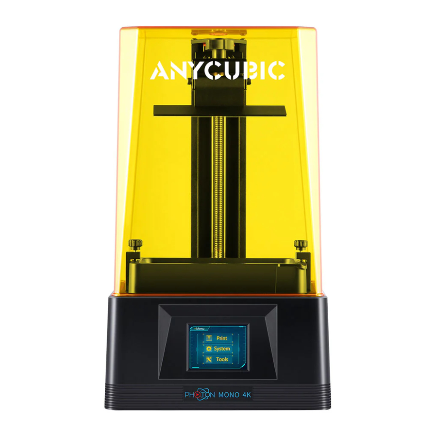
Product Overview

Menu Directory

Home menu

Print

System
Language: Change language(English/Chinese)
Service:

Information:

Tools
Move Z:

Detection:

Z=O: Reset the zero point
Lock icon: Enable/disable the door detection function
Horn icon: Turn on/off the screen sound
Assembly and Leveling Instructions
- Unpack the machine and take out the accessories. Then plug in the power cord and turn on the printer.

- Click "Tools"
![]() "Move Z"
"Move Z" ![]() "10 mm" on the touch screen to raise Z axis.
"10 mm" on the touch screen to raise Z axis.


 "Move Z"
- Unscrew four screws on the platform.

- Install the printing platform.


- Place a leveling paper on the curing screen. Then click the "Tools"
![]() "Move Z"
"Move Z" ![]() "
"![]() "on the color screen. Wait for the Z axis to descent and then it will stop automatically.
"on the color screen. Wait for the Z axis to descent and then it will stop automatically.

 "on the color screen. Wait for the Z axis to descent and then it will stop automatically.
- Finger press on top of the platform gently, to let it fit evenly on the curing screen. Then tighten the four screws on the platform.


- Lastly, click "Tools"
![]() "Z=0" on the touch screen, and then click "Enter" on the pop-up window. Till now, the leveling process is finished. Click "Enter" again on the pop-up window and pull out A4 paper.
"Z=0" on the touch screen, and then click "Enter" on the pop-up window. Till now, the leveling process is finished. Click "Enter" again on the pop-up window and pull out A4 paper.


- Testing UV light: Click "Tools"
![]() "Detection", select a image and the test time, and then click "Next" on the screen as shown below. The curing screen should display a complete image as you select. Otherwise, the UV light is malfunction and please contact the tech support.
"Detection", select a image and the test time, and then click "Next" on the screen as shown below. The curing screen should display a complete image as you select. Otherwise, the UV light is malfunction and please contact the tech support.


- Install the resin vat.


First Print Instructions
- Print
Insert the USB memory (the test file" TEST.pwmo" has been saved in it) into the USB port. Then wear masks and gloves, slowly pour the resin into the vat and the resin cannot exceed the maximum scale in the vat. After that, cover the lid and the side with sticker needs to face backward. Take off the gloves, select the "TEST.pwmo" test file and start printing. (The printing time on the screen is for reference only, we make no guarantee that it is the actual printing time.)

If you think the resin is insufficient to finish an ongoing print (or you wish to change the resin color), you can click "Pause", the platform will rise, and you can slowly pull (or change) the resin into the vat. After that, click "Start" to resume.


- Door detection function
Door detection function is disabled by default. If this function is enabled, the printer can detect whether the lid is on or not. If the lid is removed, the printing will be paused. And the printing will resume if put back the lid. Click the lock icon on "Tools" interface to enable/disable this function.


- Handling models and residues
After printing, waiting until the resin stop dropping from the platform and then unscrew and remove the platform. The model can be removed by scrapper carefully. The removed model should be washed with ethanol 95vol% concentration. The printed model may need post curing to achieve better hardness by direct sunlight or UV-curing box.


Slicing Software
Photon Mono 3D printer reads "pwmo" file and prints. It is necessary to convert 3D files (such as stl file or obj file) into pwmo files for machine to recognize. Software that convert 3D files into pwmo files is called slicing software.
- Slicing software installation
Here Windows PC is taken for example. Slicing software is located in memory stick: "File_English_Photon Mono" —Y"slicing software"* "windows". (You may have to close the anti-virus software before installing the slicing software.) Double click "Photon_WorkShop_ V2.1.23.exe", and then follow the installation guide as shown below:


- Open, save, undo and redo.
- Model mirror, hollow and infill, punching, text paste and spilt model - explained in the following parts.
- Click to switch the preset view.
- Switch between slice/machine settings and support settings.
- Drag the slider to preview each layer of the model.
- 3D model preview.
- Click to slice.
- Move, rotate, scale and layout.
- Click to switch to the AutoConfig Mode.
- Manipulate 3D model in Photon Workshop
- Model Importing
After software has been installed, please run it first. On the menu bar, Click "Configure" -4 "Machine Type" -4 "Photon Mono".

Note: Different machine types have different printing parameters. Users need to choose the correct machine. On the menu bar, click "File"* "Open file" (or click the "Open" icon at the top left (red square)) to import your own three-dimensional format model, i.e. STL file or OBJ file. Or you may input the test file (TEST.stl) in the memory stick.

- View Changing
- View changing by mouse
- Zoom in/out: scroll the mouse wheel.
- Position change: left click the platform, hold on and move the mouse.
- Change view angle: right click the platform, hold on and move the mouse.
- View changing by interface controls: click the arrow can change the viewing angle by 900in its direction.

- View changing by mouse
- Model Importing


- Model Changing
![]()
Move selected: click "move" icon, input a number or manipulate the controls can move the model. You also can center or reset the model. ![]()
Rotate selected: click "rotate" icon, input a number or manipulate the controls can rotate the model. You also can reset the model. ![]()
Scale selected: click "scale" icon, input a number or percentage or manipulate the controls can scale the model. You also can set the model to its maximum size. ![]()
Layout models: click "layout" icon, you can duplicate the model and arrange the models in X or Y direction. - Model moving

- Model rotating: Choose a larger facet as the ground fitting platform, which can improve print success rate.

- Model scaling
After setting the model to the maximum size, center it to avoid the model exceeding the print range.

- Center the model:

- Center the model:
- Layout
For multiple models, click "X Side" or "Y Side", the models can be aligned in X or Y direction.

- Model moving
- Hollow And Fill
In some cases, you don't need the model to be completely solid. Before you start slicing a model, you can hollow to reduce resin consumption.

Please check and choose the most suitable parameters for hollowing and infilling to fit your requirement.

You may drag the slider to see the internal structure of the model after hollowing.
![]()

- Punching
Although the model is hollowed, there will still be part of the resin remaining in the model after printing. By punching the model, the resin in the model can flow out, which reduces the weight of the model and the resin consumption.

The "Inner extend length" must be greater than the "Hollow thickness", so that the model can be pierced when punching and the resin can flow out of the model.

- Text Paste
You can paste text on the model with this feature.

- Add mode

- Add mode


- Left click on the model.

- Drag the slider or input the number to rotate the text.


- Delete mode
- Switch to the delete mode.

- Click the text and then click "Delete selected" to delete it.

- Click "Delete All" to delete all texts added before.

- Switch to the delete mode.


- Split model
You can split the model into several parts and then cut off the unwanted parts.

- Click the split icon, as shown in the red square above. Then make a cut across the model.

- Drag the slider to rotate the cutting surface along the XYZ axis. Then click "Generate Groups" after adjusting the cutting surface.

- Select the unwanted group from the "Split Groups". The selected group will be shown in red in the model. Click "Cut Group" to remove it.

- The effect picture after splitting the model.

- Click the split icon, as shown in the red square above. Then make a cut across the model.
- Support Settings
When the model has obvious suspended parts or overhang, it needs to add support to minimize the printing failure.
Click on the model and then click support tab to edit the support for the model. Before adding support, you can edit the shape of the support. There are three types of support, Light, Medium and Heavy. Light: Contact area between the support and model is small, and the support is easy to remove; Heavy: Support contact with the model area is large and solid.
It is recommended to try the "Medium" first, and use the default settings.
And you can always modify the support settings to fit your requirement.


- Shape editing
Click on one of these types, such as Medium. As shown below, the support is divided into three parts, namely "top", "middle" and "bottom". The settings of those three parts are described in detail below.

- Top: Set the parameters for the top of the support.

Contact Shape: Select the "Sphere" as the contact point between the top and the model can increase the contact area between the support and the model.

Contact depth: The contact depth between the support top and the model.

Contact Diameter: The contact diameter is valid when the contact shape is "Sphere".

Shape: There are two options for the top shape, "Cone" and "Pyramid".

Diameter: You can input number to change the top diameter.

Length: You can input number to change the top length.
Angle: Use the default parameter.

- Mid: Set the parameters of the mid of the support.

Shape: There are three options for the mid shape, "Cube", "Cylinder" and "Prism".

Diameter: You can input the number to change the mid diameter.

- Bottom: Set the parameters on the bottom of the support.

Shape: There are four options for the top shape, "Skate", "Cube", "Cylinder" and "Prism".

Diameter: You can input the number to change the bottom diameter.

Length: You can input the number to change the bottom length.
Contact Depth: The depth of contact between the bottom of the support and the model when the support is added inside the model.
Angle: Use the default parameter.

- Raft
In addition to the three types of support set by software, raft can be added to the model. Adding raft will increase the adhesion between model and build platform, thereby minimizing the print failure or warping risk. Select the shape of the raft as "Skate" and click "Fill" or "Platform" to add the raft and support.
Note: Before adding the raft, you need to lift the model up by a certain height in the z-axis direction.

- Lift the model up by 5mm (suggested) in the z-axis direction:
After lifting the model up, click the![]() icon to add support
icon to add support

- Lift the model up by 5mm (suggested) in the z-axis direction:
- Top: Set the parameters for the top of the support.


 icon to add support
- Support adding
You can add the support to the model manually or automatically after setting up the shape of the support.
Note: The automatic support will override all the previously set supports.- Manual Support
Add: Only after click the "Add" button then can you add the support to the model.

Delete: Click the "Delete" button first, and then click the support on the model and click "Delete" button to remove the support.

Edit: The support can be edited after clicking the "Edit" button. Click the support, it will become red. Its shape can be changed through editing the top, mid and bottom parameters. Besides, left click the model, hold on and move the mouse can change the position of the support. - Automatic Support
After setting "Auto Support Angle", "Support Min Length" and "Support Density", click "Fill" or "Platform" can automatically add supports for the model.

Auto Support Angle: The tangent angle between the model (small triangular facets) and the printing platform.

With the same "Support Density", the larger "Auto Support Angle" IS the more supports can be added.
Support Density:

Support Min Length: Use the default parameter. There are two types of support added automatically, "Vertical" and "Tree". When you choose "Tree" type, the supports can be combined and interlocked. It simplifies the supports and saves material.
After setting each parameter, click the "Fill" or "Platform" button to automatically add support.

- "Fill": The support can be added between the platform and the model, and between the model and the model.

- "Platform": The support only can be added between the platform and the model.

- "Fill": The support can be added between the platform and the model, and between the model and the model.
- Automatic support adding skills (improve print success rate)
- Properly increasing the support angle and density can optimize the support results and deliver better print quality.

When browsing on the model, by observing the contour circle, it can be found that the model still has some weak points that have not been added supports properly (highlighted by red arrows)
If we increase the automatic support angle and support density (highlighted by red square), we can see from the picture below that more supports have been added to some of the weak points.

- Manual support after Auto support (use the contour to find the weak points, add support to the local lowest point by checking the contour circle)

- Properly increasing the support angle and density can optimize the support results and deliver better print quality.
- Manual Support


- Parameter Settings
- Slice Settings The default printing mode is "Normal Mode". In this mode, four resin types are preset—"Basic", "Plant-based", "Dental Castable" and "Custom". Different resin types have different printing parameters. You can directly select the "Resin Type" according to which Anycubic Resin you are using.

You can always modify the parameters. And, you can add custom resin type. Click "Configure"![]() "Resin Manage".
"Resin Manage".
Note: Click refresh icon can restore the default parameters of the resin.

- Slice Settings The default printing mode is "Normal Mode". In this mode, four resin types are preset—"Basic", "Plant-based", "Dental Castable" and "Custom". Different resin types have different printing parameters. You can directly select the "Resin Type" according to which Anycubic Resin you are using.


Slice parameters:
- Resin Price: Set the price according to the purchased resin.
- Resin Volume: Set according to the volume of a bottle of resin you purchased. During slicing, it will automatically calculate the resin consumption and price in total.
- Layer thickness: The thicker the layer, the longer the exposure time for each layer.
- Normal exposure time: Setting range: IN4s, the exposure time is set according to the thickness of each layer, the complexity of the model details and the resin materials.
- Off time: The UV light interval between each layer is ranged 0.5-4s.
- Bottom Exposure Time: Setting range: 30-60s, the longer the bottom exposure time is, the easlier the bottom layer of the model stick onto the build platform.
- Bottom layers: Setting range: 4-10.
- Z Lift Distance: It is suggested to set it to 6mm.
- Z Lift Speed: It is suggested to set it to 4mm/s.
- Z Retract Speed: It is suggested to set it to 6mm/s.
- Anti-alias: A higher grade of anti-alias value could enhance the ability to smooth the edges for each layer during printing, thereby resulting better surface of the printed objects. A higher grade of anti-alias value also means longer slicing time and larger files. The suggested value is 1.
- Machine Settings
These parameters seldom need modification. But if the printed model shows big dimensional error along a particular axis (X,Y or Z), you can modify the corresponding values for that axis proportionally.


- Slicing
After confirm the slice settings, click the "Slice" icon at the top left (red square). You need to save the sliced file as ".pwmo" so the Photon Mono would recognize the file. Choose the file directory and save the ".pwmo" file in the memory stick and then start slicing, and click 0K to finish. You may click "Preview" to check each layer and the corresponding parameters.

In the slice file view interface, you can preview related slice settings, machine settings, single layer settings and other information.

In the Sliced File View interface, check "Enabled" to set the exposure time, Z lift distance and Z lift speed of the current layer according to personal requirements. Upon finished, click "File"![]() "Save File"on the upper left corner to save as a new sliced file.
"Save File"on the upper left corner to save as a new sliced file.

Note:


- This function is invalid for the bottom layers. Do not use this function to bottom layers.
- After changing the individual layer settings, the exposure parameters of the new file cannot be modified again via the printer touch screen during printing. Even if it has been modified, the change would only be valid for the current layer.
- R_E_R_ F
"R_E_R_ F" is an abbreviation for "Resin Exposure Range Finder". This function is used to find out the optimal exposure parameters for different resins. Import the "R_E_R_F.pwmo" file into the slicing software (The file has been saved into the memory stick). Specifically, in the R_E_R_F mode, the curing screen will be divided into eight areas and each area is numbered, as shown in the picture.


- The exposure time for Area No. 1 is equal to "normal exposure time (s)" in the slicing settings (exclude Bottom Exposure Time), and the exposure time for other areas will be increased by an increment of "0.4s" subsequently.
- For example, when "Normal Exposure Time (s)" is set to 3s in the slicer, the exposure time for Area No. 1 is 0.8s, the exposure time for Area No.2 will be 1.2s, and so on, and the exposure time of Area 8 will be 3.6s.
- You can modify the exposure time of Area No. 1 by modifying the "Normal Exposure Time (s)" parameter, and this action is also valid during printing.
The normal exposure parameter of "R_E R_F.pwmo" file attached to memory stick is 0.8, and users can print this file directly for testing. After printing, take off the model, wash it with ethanol 95vol% concentration, and then observe it. The exposure parameters of the model with the best printing effect are the best exposure parameters of the resin.
Note: DO NOT change the file name of "R E R F" because the Photon Mono can only recognize THIS file name to run this function. Also, do not name other unrelated file as "R E R F".
FAQ
Model do not stick to platform
- Bottom exposure time is insufficient, increase the exposure time.
- Contact area between the model and platform is small, please add raft.
- Bad leveling
Layer separation or splitting
- The machine is not stable during printing
- FEP film in the vat is not tight enough or it need a change for new one
- The printing platform or vat is not tightened
Machine Maintenance
- If Z axis make noisy sound, please apply lubricant to Z lead screw.

- Do not use sharp objects to scrape off the residues on the FEP film.


Safety Instructions
Always follow the safety instructions during assembly and usage, to avoid any unnecessary damage to the 3D printer or individual injury
 | Please contact our customer service first if you have any issue after receving the products. |
 | Be cautious when using the scraper. Never direct the scraper towards your hands. |
 | In case of emergency, please immediately cut off the power of ANYCUBIC 3D printer and contact the technical support. |
 | ANYCUBIC 3Dprinter includes moving parts that can cause injury. |
 | It is recommended to use protection glasses when cleaning/ sanding the printed models to avoid small particles contacting eyes. |
 | Keep the ANYCUBIC 3D printer and its accessories out of the reach of children. |
 | Vapors or fumes may be irritating at operating temperature. Always use the ANYCUBIC 3D printer in an open and well ventilated area. |
 | ANYCUBIC 3D printer must not be exposed to water or rain. |
 | ANYCUBIC 3D printer is designed to be used within ambient temperature ranging 8ºC-40ºC, and humidity ranging 20%-50%. Working outside those limits may result in low quality printing. |
 | Do not disassemble ANYCUBIC 3D printer, please contact technical support if you have any question. |
Technical Specification
Printing
| System | ANYCUBIC Photon Mono |
| Operation | 2.8-inch Color TFT Screen |
| Software | ANYCUBIC Photon Workshop |
| Connectivity | USB memory stick |
Specifications
| Technique | LCD Shadow Masking |
| Light source | UV-LED (wavelength 405nm) |
| XY Resolution | 0.051mm 2560x1620 (2K) |
| Z axis Accuracy | 0.01 mm |
| Suggested Layer Thickness | 0.01 - 0.15 mm |
| Print Speed | Max 50mm/h |
| Rated power | 45W |
Physical Dimensions
| Dimension | 222mm (L) *227mm (W) *383mm (H) |
| Build volume | 130mm (L) *80mm (W) *165mm (H) |
| Materials | 405nm UV-resin |
| Net weight | N4.25kg |
Recommended Printing Parameters
| Layer Thickness | 0.05 mm |
| Normal Exposure Time | 2s |
| Off Time | 0.5 s |
| Bottom Exposure Time | 45 s |
| Bottom Layers | 6 |
| Z Lift Distance | 6 mm |
| Z Lift Speed | 4 mm/s |
| Z Retract Speed | 6 mm/s |
| Anti-alias | 1 |
Documents / ResourcesDownload manual
Here you can download full pdf version of manual, it may contain additional safety instructions, warranty information, FCC rules, etc.
Advertisement


Need help?
Do you have a question about the PHOTON MONO and is the answer not in the manual?
Questions and answers