Table of Contents

Summary of Contents for NS system Tango-B series
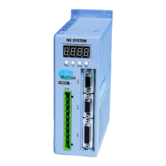
- Page 1 User's Manual 1-AXIS AC SERVO DRIVE & CONTROLLER TANGO-B Series NS SYSTEM Co., Ltd. NS SYSTEM SinYong B/D 4F #942-6 Ingye-Dong, Paldal-Gu, Suwon-City, Kyungki-Do, Korea Homepage : www.nssystem.co.kr TEL: 82-31-235-7492~6 FAX: 82-31-235-7497...
-
Page 2: Table Of Contents
CONTENTS Safety Instructions CHAPTER 1. FUNCTIONS AND SPECIFICATIONS 1-1. FEATURES AND THE PRODUCT 1-2. OPERATION MODE 1-3. STANDARD SPECIFICATIONS 1-4. MODEL CODE DEFINITION 1-4-1. NAME PLATE 1-4-2. MODEL CODE 1-5. COMBINATION WITH SERVO MOTOR 1-6. DIMENSIONS OF SERVO AMPLIFIER 1-6-1. DIMENSIONS OF BOOK TYPE1 ( TANGO-B01/B02/B04/B06 ) 1-6-2. - Page 3 CHAPTER 5. SETUP PARAMETER MODE 5-1. DEFINITION OF SETUP PARAMETER 5-2. SELECTION OF SETUP PARAMETER MODE 5-3. OPERATION OF THE LOADER 5-4. OPERATION OF THE SERVO KEY UNIT 5-5. DETAILED DESCRIPTION OF SETUP PARAMETERS CHAPTER 6. SERVO PARAMETER MODE 6-1. DEFINITION OF SERVO PARAMETER 6-2.
- Page 4 CHAPTER 11. HOME RETURN MODE 11-1. HOME RETURN METHOD 11-2. SETUP PARAMETERS FOR HOME RETURN 11-3. HOME RETURN SEQUENCE 11-4. HOME RETURN ERROR 11-5. PRECAUTIONS OF HOME RETURN CHAPTER 12. CHECK MODE 12-1. SELECTION OF CHECK MODE 12-2. INPUT CHECK MODE 12-3.
- Page 5 CHAPTER 20. SUMMARY OF LISTS 20-1. SETUP AND SERVO PARAMETER LISTS 20-2. INSTRUCTION (CODE) LISTS 20-3. ERROR (ALARM) LISTS 20-4. DISPLAY MODE LISTS 20-5. CHECK MODE LISTS 20-6. COMBINATION OF AMPLIFIERS AND MOTORS 20-7. SERVO PARAMETER INITIAL VALUE AT FACTORY SETTING CHAPTER 21.
-
Page 6: Safety Instructions
Safety Instructions (After being familiar with this user's manual, use the TANGO Series Servo Drive.) Do not attempt to install, operate, maintain or inspect the servo amplifier and motor until you have read through this User's Manual and appended documents carefully. After reading all, keep the manual well in order that the user of product can easily access it. - Page 7 CAUTION ☞ To prevent injury, note the following: ▶ Care must be taken during the transportation. Falling to the foot may cause the injury. ▶ Only the voltage specified in the User's Manual should be applied to each terminal. Otherwise, a burst, damage, etc. may occur. ▶...
- Page 8 CAUTION ☞ Wiring ▶ Wire the equipment correctly. Otherwise, the servo motor and amplifier may be damaged. ▶ Connect the output terminals(U, V, W, FG) correctly. Otherwise, the servo and amplifier may be damaged. ▶ Do not install a power capacitor, surge absorber or radio noise filter between the servo motor and servo amplifier.
-
Page 9: Chapter 1. Functions And Specifications
CHAPTER 1. FUNCTIONS AND SPECIFICATIONS 1-1. FEATURES AND THE PRODUCT The NS SYSTEM "TANGO-B" series general purpose AC servo motor drive and controller is the full-digital AC servo for high speed and accuracy by use of 32bit intelligent DSP. It is applicable to wide range of FA fields, not only precision positioning of machine tools and general automatic industrial machines but also line speed control and 1-axis robot control. -
Page 10: Standard Specifications
1-3. STANDARD SPECIFICATIONS [ SMALL SIZED STANDARD SERVO CONTROLLER SPECIFICATIONS ] Model TANGO TANGO TANGO TANGO Item Voltage/frequency 3-phase AC 220 [V] +10~-15%, 50/60[Hz]±5% Power supply Capacity [kVA] Flux shape 3-phase sine-wave AC servo motor 30 / 50 / 300 / 400 / Rated output 200[W] 500 / 600[W]... - Page 11 [ MIDDLE SIZED STANDARD SERVO CONTROLLER SPECIFICATIONS ] Model TANGO TANGO TANGO Item Voltage/frequency 3-phase AC 220 [V] +10~-15%, 50/60[Hz]±5% Power supply Capacity [kVA] Flux shape 3-phase sine-wave AC servo motor 0.9 / 1.0 / 1.2 / Rated output 750 / 850[W] 1.5 / 1.8 / 2.0[KW] 1.3[KW] Applicable...
- Page 12 [ LOWER LARGE SIZED STANDARD SERVO CONTROLLER SPECIFICATIONS ] Model TANGO TANGO TANGO Item Voltage/frequency 3-phase AC 220 [V] +10~-15%, 50/60[Hz]±5% Power supply Capacity [kVA] Flux shape 3-phase sine-wave AC servo motor Rated output 1.8 / 2.0 / 2.5[KW] 2.9 / 3.0[KW] 3.5[KW] Applicable motor...
- Page 13 [ LARGE SIZED STANDARD SERVO CONTROLLER SPECIFICATIONS ] Model TANGO TANGO TANGO TANGO Item Voltage/frequency 3-phase AC 220 [V] +10~-15%, 50/60[Hz]±5% Power supply Capacity [kVA] 10.0 15.0 Flux shape 3-phase sine-wave AC servo motor Rated output 4.0[KW] 4.4/4.5/5.0[KW] 6.0/6.5/7.5[KW] 11.0[KW] Applicable motor Max.
-
Page 14: Model Code Definition
1-4. MODEL CODE DEFINITION 1-4-1. NAME PLATE Model name Capacity Input power Serial number 1-4-2. MODEL CODE TANGO - □ □□ Series Capacity name Amplifier type model type symbol output symbol output symbol output symbol output General-purpose 0.1kw 0.8kw 3.0kw 7.5kw 1 axis controller 0.2kw... -
Page 15: Dimensions Of Servo Amplifier
1-6. DIMENSIONS OF SERVO AMPLIFIER 1-6-1. DIMENSIONS OF BOOK TYPE1 ( TANGO-B01/B02/B04/B06 ) 1-6-2. DIMENSIONS OF BOOK TYPE2 ( TANGO-B08/B12/B18 ) -
Page 16: Dimensions Of Base Mount Type1 ( Tango-B24/B30/B35 )
1-6-3. DIMENSIONS OF BASE MOUNT TYPE1 ( TANGO-B24/B30/B35 ) 1-6-4. DIMENSIONS OF BASE MOUNT TYPE2 ( TANGO-B40/B50/B75 ) -
Page 17: Dimensions Of Operating Loader
1-7. DIMENSIONS OF OPERATING LOADER ( Dimensions of panel loader ) ( Dimensions of handy loader ) ( Dimensions of panel loader cutting) -
Page 18: Chapter 2. Installation
CHAPTER 2. INSTALLATION 2-1. CHECK ITEMS WHEN PRODUCT DELIVERED Check the following items first when the product is delivered. Check whether the product conforms to the ordered specifications. Check whether the product is not damaged. Check whether the coupling part is loosened. Check whether the motor shaft is smooth and no stalled feeling when turned by hand. -
Page 19: Installation Of Servo Motor
2-2-2. INSTALLATION OF SERVO MOTOR The servo motor is available for both vertical and horizontal installation. But since the bad environment of the installation condition affects the lifetime of motor and the unexpected accident, it should be installed according to the following descriptions. ☞... -
Page 20: Auxiliary Equipments And Wires
2-2-5. AUXILIARY EQUIPMENTS AND WIRES ■ Power supply : 3-phase AC 200V ~ 230V Amplifier Wire[ ] ㎟ Amplifier Wire[ ] ㎟ Amplifier Wire[ ] ㎟ TANGO-B01 2(AWG14) TANGO-B12 2(AWG14) TANGO-B40 5.5(AWG10) TANGO-B02 2(AWG14) TANGO-B18 3.5(AWG12) TANGO-B50 5.5(AWG10) TANGO-B04 2(AWG14) TANGO-B24 3.5(AWG12) TANGO-B75 8(AWG8) TANGO-B06 2(AWG14) TANGO-B30 5.5(AWG10) TANGO-BH1 13(AWG6) TANGO-B08 2(AWG14) TANGO-B35 5.5(AWG10) -
Page 21: Chapter 3. Parts Identification
CHAPTER 3. PARTS IDENTIFICATION 3-1. PARTS IDENTIFICATION OF SERVO AMPLIFIER 3-1-1. PARTS IDENTIFICATION OF BOOK TYPE1 / TYPE2 BOOK TYPE1 : TANGO-B01/B02/B04/B06 BOOK TYPE2 : TANGO-B08/B12/B18 CN1 Control I/O connector CN2 Loader connector CN3 Servo motor encoder connector R, S, T, E : AC input power P, B : Regenerative brake U, V, W, FG : Servo motor power CN6 Communication connector... -
Page 22: Parts Identification Of Operating Loader
3-2. PARTS IDENTIFICATION OF OPERATING LOADER Functions Functions Button Button System reset Positiveness of the set data RESET + Program mode 1-STEP Insert of the program SHIFT+F1 SHIFT+ + Manual mode Negativeness of the set data SHIFT+F2 - Setup parameter mode 1-STEP Delete of the program SHIFT+F3 SHIFT+ -... -
Page 23: Chapter 4. Signals And Wiring
CHAPTER 4. SIGNALS AND WIRING 4-1. CONNECTION DIAGRAM OF BOOK TYPE1 / TYPE2 4-2. CONNECTION DIAGRAM OF BASE MOUNT TYPE1 / TYPE2... -
Page 24: I/O Signals Of Cn1 (Control Signals)
4-3. I/O SIGNALS OF CN1 (CONTROL SIGNALS) 4-3-1. SIGNAL LAYOUTS AND ASSIGNMENT [CN1 signal layout] [CN1 signal assignment] Signal Signal Signal No. Symbol No. Symbol No. Symbol Name Name Name Output Output Output OUT6 10 OUTCOM OUT7 common Output Output Output OUT3 OUT5... -
Page 25: Output Interface
4-3-3. OUTPUT INTERFACE All output interface signals are isolated by photo-coupler. Each output port has the capacity of 100Vdc, 120mA. The surge absorbing diode installed on the DC output signal relay must be wired in the specified direction. Otherwise, the servo amplifier output is damaged by over-current permanently. - Page 26 Name Pin Functions * INPUT 4 / HOME : Setup-24 "I4/HM" determines it's function. General-purpose input One-Touch type of external home input * INPUT 5 / HOME SENSOR : Setup-25 "I5/HS" determines it's function. General-purpose input Home sensor (normally open) Home sensor (normally close) * INPUT 6 / LEFT(CW) LIMIT SENSOR : Setup-26 "I6/LL"...
- Page 27 Name Pin Functions * OUTPUT 0 / RUNNING MONITOR : Setup-31 "O0/RN" determines it's function. OUT0 General-purpose output Running monitor output * OUTPUT 1 / ERROR MONITOR : Setup-32 "O1/ER" determines it's function. OUT1 General-purpose output Error monitor output * OUTPUT 2 / MACHINE READY MONITOR : Setup-33 "O2/MR" determines it's function.
-
Page 28: Motor Encoder Signals Of Cn3
4-4. MOTOR ENCODER SIGNALS OF CN3 Symbol Name B phase input /Z phase input V phase input /W phase input Shield A phase input /B phase input U phase input /V phase input 5V power /A phase input Z phase input /U phase input W phase input 5V ground... -
Page 29: Chapter 5. Setup Parameter Mode
CHAPTER 5. SETUP PARAMETER MODE 5-1. DEFINITION OF SETUP PARAMETER Setup means the act of input the basic information about mechanical system (parameter) into controller by the manufacturer of the system. Therefore, users must be careful when they want to change the setup parameters. -
Page 30: Operation Of The Servo Key Unit
5-4. OPERATION OF THE SERVO KEY UNIT A built-in servo key unit provides the cost-effective and convenient editing function without optional loader. When the servo amplifier is in servo-off, It is possible to enter the setup parameter mode by the servo key unit. Editing sequence is as follows. Operation Push the MODE key to change from "status display"... -
Page 31: Detailed Description Of Setup Parameters
5-5. DETAILED DESCRIPTION OF SETUP PARAMETERS Range No. Name Description Min. Max. * PROGRAM FILE NUMBER The file number to be run in automatic operation is set. There are 16 files (00~15) and each file is composed of 96 steps. If the setting value is 16, The file number to be run in automatic operation is determined by external BCD input (input-13,12,11,10) from FILE#... - Page 32 Range No. Name Description Min. Max. * MANUAL HIGH SPEED 1500 06 MANSP Settings of the speed in high speed manual operation. The unit is rpm. 5000 * MANUAL JOG(LOW) SPEED 1500 07 JOGSP Settings of the speed in jog(low) speed manual operation. The unit is rpm.
- Page 33 Range No. Name Description Min. Max. * ALLOWABLE HOME TIME Setting of the allowed time for home return. The unit is 0.1sec. If home return is not successful within the allowed time owing to the HTIME malfunction of home sensor, amplifier, mechanical error, etc., home return stops and error message ( is displayed.
- Page 34 Range No. Name Description Min. Max. * HOME HIGH SPEED Setting of the high home return speed to find home sensor. The unit is rpm. Also, this speed is applied when home offset movement is done. If the setting value is too high against deceleration time and dog width, 1500 it may cause a malfunction of home return.
- Page 35 Range No. Name Description Min. Max. * INPUT 0 / RUN Determine whether the input 0 is used for "general-purpose input" or "external run input". I0/RN General-purpose input One-touch type of external run input * INPUT 1 / STOP Determine whether the input 1 is used for "general-purpose input" or "external stop input".
- Page 36 Range No. Name Description Min. Max. * INPUT 6 / LEFT(CW) LIMIT SENSOR Determine whether the input 6 is used for "general-purpose input" or "external left(CW) limit sensor input". General-purpose input Left(CW) limit sensor (normally open) I6/LL Left(CW) limit sensor (normally close) Left/right limit direction may change according to the installed method of motor.
- Page 37 Range No. Name Description Min. Max. * OUTPUT 0 / RUNNING MONITOR Determine whether the output 0 is used for "general-purpose output" or "running monitor output". O0/RN General-purpose output Running monitor output * OUTPUT 1 / ERROR MONITOR Determine whether the output 1 is used for "general-purpose output" or "error monitor output".
- Page 38 Range No. Name Description Min. Max. * DEVICE ID Used to set the device identity number for the serial communication. The setting value should be "0" when the serial communication is not used. The servo amplifier responds to the request of host when ID. RS232 number is matched.
- Page 39 Range No. Name Description Min. Max. * INDEX MODE If this value is set in "0", mm unit is available. If this value is set in "1", inch unit is available. If this value is set in "2", index mode is available. Index mode changes it's coordinate system from mm(inch) to degree.
- Page 40 Range No. Name Description Min. Max. * EXTERNAL ENCODER DIRECTION Determine the optional function of external encoder or MPG. This function supplies the special operations such as manual movement by MPG, synchronous movement of flying cutter and etc. 47 ENCDR Not used The A phase is 90°...
- Page 41 Range No. Name Description Min. Max. * DIRECTION CHANGE OF MANUAL INPUT Determine the moving direction in accordance with external manual inputs or loader manual keys. It is uncomfortable from the view of common sense, when the moving direction according to the manual movement inputs is opposite from 54 MANDR the real mechanical direction.
-
Page 42: Chapter 6. Servo Parameter Mode
CHAPTER 6. SERVO PARAMETER MODE 6-1. DEFINITION OF SERVO PARAMETER Servo parameter is the basic information about servo control variables and servo motor. Therefore, users must be careful when they want to change the servo parameters. For the trouble shooting and maintenance, the setting value of servo parameters are in need of document recording. -
Page 43: Operation Of The Servo Key Unit
6-4. OPERATION OF THE SERVO KEY UNIT A built-in servo key unit provides the cost-effective and convenient editing function without optional loader. When the servo amplifier is in servo-off, It is possible to enter the servo parameter mode by the servo key unit. Editing sequence is as follows. Operation Push the MODE key to change from "status display"... -
Page 44: Detailed Description Of Servo Parameters
6-5. DETAILED DESCRIPTION OF SERVO PARAMETERS Range No. Name Description Min. Max. * GAIN SELECTION Determine the type of servo control gains (the manual input gains or the auto tuning gains). The servo control gains are composed of position P-gain, speed P-gain, speed I-gain. The manual input gains are preferable to the auto tuning gains for the 00 AUTOT 1000... - Page 45 Range No. Name Description Min. Max. * SPEED I-GAIN INHIBITION The speed I-gain function is disabled when this value is set in "1". In the result, the structure of speed controller is changed from PI to P control regardless of speed I-gain value. If the servo motor at a stop is rotated even one pulse due to an external factor, it generates torque to compensate for a position mismatch.
- Page 46 Range No. Name Description Min. Max. * REGERATION BRAKE TIME Set the allowable maximum time of regenerative brake action. The brake resistor is optional. The converter voltage of servo amplifier is increased in case of regeneration in which the energy is transferred reverse to the servo amplifier from the motor.
- Page 47 Range No. Name Description Min. Max. * AUTO TUNING POSITION P-GAIN Used to set the auto tuning P-gain for position loop. It is applicable when servo parameter Svpar-00 is set in 1. This parameter is automatically adjusted and saved at the end of auto tuning action or manually edited in servo parameter edit mode.
-
Page 48: Special Servo Parameters
6-6. SPECIAL SERVO PARAMETERS The special servo parameters have the items (motor constants, etc.) for factory setting. The user can not set or change the special servo parameter. Range No. Name Description Min. Max. * CURRENT P-GAIN 00 CURPG 1000 Used to set the P-gain for current loop. -
Page 49: Chapter 7. Program Mode
CHAPTER 7. PROGRAM MODE 7-1. SELECTION OF PROGRAM MODE If you push the button "SHIFT+F1" in run ready state, you can select the program edit mode in the following display. It makes the servo amplifier to be automatically servo-off. 0 0 - 0 0 - F 0 0 + 0 1 0 0 0 0 0 0 - 0 1 - G 0 8 + 0 0 0 0 1 0 <... - Page 50 H. The case of wrong number input Place the cursor at the number you want to change and re-enter the correct number. Or, if you push the button , the cursor moves to left direction and deletes letters one by one. "SHIFT BACK"...
-
Page 51: Operation Of The Servo Key Unit
7-3. OPERATION OF THE SERVO KEY UNIT Operation Push the MODE key to change from "status display" to mode A built-in servo key unit provides the selection level. cost-effective and convenient editing 1. The pre-saved mode is displayed at LED. function without optional loader. -
Page 52: Detailed Description Of Program Commands
7-4. DETAILED DESCRIPTION OF PROGRAM COMMANDS Range Command Description Min. Max. * POSITIONING Move to the designated position. In case of incremental coordinate system, moving direction is determined by the sign of data and distance is determined by the absolute value of data. - Page 53 Range Command Description Min. Max. * POSITIONING BY BCD. Move to the point data position appointed by external BCD input. Point data exist in Setup area (16 point : Setup-60 ~ Setup-75). This command is mainly used in absolute coordinate system. External BCD input is determined by input-13,12,11,10.
- Page 54 Range Command Description Min. Max. * BLOCK POSITIONING If the current position is equal with designated comparison position, then make the designated output on or off while it moves to the designated position set by command data. The block positioning command (G99) should be ended by the block end command (G30).
- Page 55 Range Command Description Min. Max. * CONTINUOUS SPEED RUN Rotate the servo motor at constant designated speed. The unit is rpm The rotational direction is determined by the sign of the data (" "=CW, + " "=CCW) and speed is determined by the absolute value of data. -...
- Page 56 Range Command Description Min. Max. * DWELL Wait for the set time. The unit is 0.01sec After a lapse of set time, it continues to execute the next step. It is used for delay after positioning end or for timing of in/out process. [Example] Description File Step Code...
- Page 57 Range Command Description Min. Max. * POSITION RESET Reset the coordinate value to the designated data. If G92 is processed, the present coordinate value changes to the designated data. [Example] Description File Step Code Data -999999 +999999 Declaration of incremental coordinate +1000 Continuous run at +1000 rpm Wait for input-2 on...
- Page 58 Range Command Description Min. Max. * SUBTRACT POSITION FROM STORAGE POINT Subtract the designated position value from the designated storage point. [Usage] (00 ~ 03)X10000 + (0000 ~ 9999) Upper 2 figures Lower 4 figures Storage point no. Value to be subtracted [Example] Description File Step Code...
- Page 59 Range Command Description Min. Max. * POSITIONING SPEED Used to set the positioning speed. The unit is rpm. It is continuously valid until "F00" is re-declared. If "F00" is not set in program, the positioning speed is automatically set by the Setup-01 "BSSPD". 5000 [Example] Description...
- Page 60 Range Command Description Min. Max. * PAUSE Give pause to advance of program. If the RUN Key is pushed or external RUN input is on, it starts again. It is used when manual operation is required in automatic operation or when step by step operation is required for checking of program.
- Page 61 Range Command Description Min. Max. * SUBROUTINE CALL Call the subroutine program which begins at the designated step in a file. Subroutine call must be ended by "M42" (return from subroutine). When the program meets the command "M42", it returns to the main program from the subroutine by "M40".
- Page 62 Range Command Description Min. Max. * ERROR STOP If the program meets the command "M64", then the motion stops and error message ("ERROR CODE STOP ") is displayed. [Example] Description File Step Code Data +0106 If input-1 is on then jump to step "6" G00 +10000 Move +100.00 mm Jump to step "3"...
- Page 63 Range Command Description Min. Max. * OUTPUT ON Turn on the designated output. If the output number is out of range, then the motion stops and error message ("OUT RANGE OVER ") is displayed. [Example] Description File Step Code Data Output-1 on * OUTPUT OFF Turn off the designated output.
- Page 64 Range Command Description Min. Max. * MULTI INPUT COMPARE Compare the on or off states of the multiple inputs with designated value. If not equal then go to the next step(+1). Or if it equal, jump to the next but one step(+2). If the designated value is out of range (00~15), then motion...
- Page 65 Range Command Description Min. Max. * INPUT ON JUMP Jump to the designated step in a file if the designated input is on, or jump to the next step if the designated input is off. If the designated value is out of range (00~13), then the motion stops and error message ("INPUT RANGE OVER") is displayed.
- Page 66 Range Command Description Min. Max. * WORK COUNTER SET The initial value of work counter is set in the designated value. The work counter is used for counting the total output production. If the display mode is set at counter mode ( mode 1), the work counter and general-purpose counter 0 is displayed.
- Page 67 Range Command Description Min. Max. * GENERAL-PURPOSE COUNTER EQUAL JUMP If the counter value is equal to the designated number after "M29" is executed, jump to the designated step. Otherwise, go to the next step. [Example] Description File Step Code Data Initial value of counter0 is set in "0"...
-
Page 69: Chapter 8. Run Ready Mode
CHAPTER 8. RUN READY MODE 8-1. STATUS DISPLAY The handy loader or panel loader displays as follows when the power is on. The first displayed screen when the power is on can be selected at the Setup-45 "DISPL" (0=display0, 1=display1, 2=display2). Whenever you push the "0"... -
Page 70: Operation
8-2. OPERATION 8-2-1. OPERATION OF THE LOADER A. Auto-run mode : If you push the button "RUN", the program of file which is selected by Setup-00 "FILE#" is run automatically. There are 16 files (00~15) and each file is composed of 96 steps. If the setting value is 16, The file number to be run in automatic operation is determined by external BCD input (input-13,12,11,10) from the master device (PLC, switches, etc.). -
Page 71: Operation Of The External Input
H. Check mode : If you push the button "SHIFT+F5", you can select the check mode. It makes the servo amplifier to be automatically servo-off. I. Display mode : Whenever you push the "0" button, the run ready state displays are sequentially changed. 8-2-2. -
Page 72: Selection Of Display Mode By The Servo Key Unit
8-3. SELECTION OF DISPLAY MODE BY THE SERVO KEY UNIT A built-in servo key unit provides the cost-effective and convenient display selection function without optional loader. When the servo amplifier is in servo-off, It is possible to enter the display mode by the servo key unit. -
Page 73: Chapter 9. Auto Run Mode
CHAPTER 9. AUTO RUN MODE 9-1. START OF AUTO RUN If you push the button "RUN", or "external run input" is on (when the Setup-20 "I0/RN" is set in "1") the program of file which is selected by Setup-00 "FILE#" is run automatically. There are 16 files (00~15) and each file is composed of 96 steps. -
Page 74: Reset And Emergency Stop
9-4. RESET AND EMERGENCY STOP In the case of emergency, if you push the button "RESET" or "external reset input (input 2)" is on (when the Setup-22 "I2/RS" is set in "1"), all the system resets to the first state when the power is on. -
Page 75: Escaping From Limit State
9-7. ESCAPING FROM LIMIT STATE A. Screen display at limit state S Y S T E M E R R O R : 0 7 S Y S T E M E R R O R : 0 8 L E F T E N D A L A R M R I G H T... -
Page 76: Chapter 10. Manual Mode
CHAPTER 10. MANUAL MODE 10-1. OPERATION OF THE LOADER If you push the button "SHIFT+F2" in run ready state, you can select the manual mode. The servo amplifier should be in servo-on before any manual operation is performed. If the Setup-44 "SERVO" ("auto servo on" function) is set in "1", it makes the servo amplifier to be automatically servo-on before operation. -
Page 77: Operation Of The External Input
Return to run ready state If you push the "ESC" button, it will return to the run ready state. 10-2. OPERATION OF THE EXTERNAL INPUT The input 3 is used for "external manual input" when the Setup-23 "I3/SM" is set in "2". If "external manual input"... -
Page 78: Chapter 11. Home Return Mode
CHAPTER 11. HOME RETURN MODE 11-1. HOME RETURN METHOD The home return function is performed according to the method set by Setup-13 "HFILE" as follows. General home return Program file number for complex home return (max. 48 step) 1 ~ 15 The complex home return provides an another home return function which requires complex motion (general home, additional motion, in/out functions, etc.). -
Page 79: Setup Parameters For Home Return
11-2. SETUP PARAMETERS FOR HOME RETURN Description Name * ALLOWABLE HOME TIME Setting of the allowed time for home return. The unit is 0.1sec. If home return is not successful within the allowed time owing to the malfunction of HTIME home sensor, amplifier, mechanical error, etc., home return stops and error message ("HOME OVER TIME") is displayed. - Page 80 Description Name * HOME OFFSET POSITION After the mechanical home is set by home sensor or Z phase, the 2nd home (work home) is set by moving the amount of offset value. The unit of offset value is determined by Setup-05 "BUNIT", moving speed is 19 HMOFF determined by Setup-15 "HMSPD"...
-
Page 81: Home Return Sequence
11-3. HOME RETURN SEQUENCE The operating sequence of home return are as follows. 1. Determine the contact logic of home sensor at Setup-25 "I5/HS". 2. Determine the contact logic of left limit sensor at Setup-26 "I6/LL". 3. Determine the contact logic of right limit sensor at Setup-27 "I7/RL". 4. -
Page 82: Precautions Of Home Return
11-5. PRECAUTIONS OF HOME RETURN A. The width of the sensor detection dog of the home, left limit and right limit sensor should be so wide that the system does not pass the sensor even when it decelerates and stops at high speed. If the width is too narrow, the system will pass the sensor when it decelerates and stops. -
Page 83: Chapter 12. Check Mode
CHAPTER 12. CHECK MODE 12-1. SELECTION OF CHECK MODE If you push the button "SHIFT+F5" in run ready state, you can select the check mode in the following display. It makes the servo amplifier to be automatically servo-off. Also, it makes all outputs to be off. 2 = I N P U T , 4 = O U T P U T <... -
Page 84: Chapter 13. Servo Check Mode
CHAPTER 13. SERVO CHECK MODE A built-in servo key unit provides the cost-effective and convenient diagnostic functions without optional loader. When the servo amplifier is in servo-off, It is possible to enter the servo check mode by the servo key unit. Editing sequence is as follows. 13-1. - Page 85 Description Name * INVERTER H/W CHECK Check the inverter(dc-link) H/W. Display the peak value of AC voltage input. C-04 The peak value is times as nominal voltage. Usage : used to check the AC voltage input and inverter H/W. (Example). If input voltage is AC 220V, it displays "310" * U PHASE CURRENT SENSOR OFFSET Check the offset value of U phase current sensor.
- Page 86 Description Name * OUTPUT CHECK Usage : used to check the output ports and wiring mistake. Output selection: Select the output no.(00~07) C-12 by UP/DOWN key. Selected output no. is displayed. Output on/off : The selected output is toggled. ( H: ON, L: OFF ) * EXTERNAL ENCODER (MPG) CHECK Check the external encoder A/B phase for auxiliary function.
-
Page 87: Chapter 14. Error (Alarm) Status
CHAPTER 14. ERROR (ALARM) STATUS CAUTION When any alarm has occurred, eliminate it's cause, ensure safety, and deactivate the alarm ☞ before restarting operation. Otherwise, the servo motor and amplifier may be damaged. - Alarm output (output 1) when alarm status. If the Setup-32 "O1/ER"... -
Page 88: Detailed Description Of Error Items
14-2. DETAILED DESCRIPTION OF ERROR ITEMS A. Detailed description of system errors LOADER KEY ALARM Display Loader button is pressed when power-on or reboot. Contents 1. Loader H/W faulty. Change the loader or loader cable. Cause & 2. Loader operation mistake. Review operation. - Page 89 RIGHT END ALARM Display Right H/W limit is operated in automatic operation. Contents 1. Right H/W limit is normally active. Eliminate it's cause 2. Contact logic is mismatched. Change contact logic (Setup-27 "I7/RL"). Cause & 3. Out of the set value of S/W limit. Change the S/W limit values(Setup-42 Action “SEND-“) or review program.
- Page 90 OVER REG. ALARM Display Operation time of regenerative brake exceeded the allowed time(Svpar-09 "REGTM") Contents 1. Acc./dec. time is too small when Increase the acc./dec. time. regenerative brake resistor is not installed 2. Acc./dec. time is too small when Increase the acc./dec. time. regenerative brake resistor is installed.
- Page 91 B. Detailed description of program errors (M10-M11) LOOP I Display "M11" cannot make a loop. Contents "M11" is met without the declaration of Review program and remove the error. Cause & "M10". Action (M12-M13) LOOP J Display "M13" cannot make a loop. Contents "M13"...
- Page 92 Reserved Display Contents Cause & Action SYNTAX ERROR Display There is wrong command that is not allowed. Contents Review program. Cause & There is wrong command. Action Perform system initialization. ERROR CODE STOP Display The case when error is made by the command "M64". Contents Cause &...
-
Page 93: Chapter 15. Servo Gain Tuning
CHAPTER 15. SERVO GAIN TUNING 15-1. MANUAL GAIN TUNING The position P-gain, speed P-gain and speed I-gain is set to satisfy no-load condition at factory setting. Therefore, when the motor is installed to the machine, the gain must be adjusted to satisfy the load inertia condition. -
Page 94: Semi-Auto Gain Tuning
15-2. SEMI-AUTO GAIN TUNING Operation Preparation: Set the value of "auto tuning inertia ratio" in servo parameter Svpar-15 "INERT". Push the MODE key to change from "status display" to mode selection level. 1. The pre-saved mode is displayed at LED. Each modes are scrolled sequentially by UP/DOWN key. -
Page 95: Chapter 16. Signal Timing
CHAPTER 16. SIGNAL TIMING 16-1. POWER ON SEQUENCE The servo amplifier can accept the servo-on signal about 2sec. after the main circuit power supply is switched on. Also, the external reset input makes the same effect as power-on sequence. The minimum pulse width of reset input is 50msec and the maximum of that is 0.2sec. -
Page 96: Chapter 17. Options
CHAPTER 17. OPTIONS 17-1. ENCODER AND MOTOR CABLE (ENCODER CABLE) Applicable Model name Length motor NSAE-3M KANZ NSAE-5M KANQ NSAE-10M Applicable Model name Length motor NSME-3M KAND/S/H/F NSME-5M KAFX/N NSME-10M (MOTOR CABLE) Applicable Model name Length motor NSAP-3M KANZ NSAP-5M KANQ NSAP-10M Applicable... -
Page 97: Optional Regenerative Brake Resistor
17-3. OPTIONAL REGENERATIVE BRAKE RESISTOR The converter voltage of servo amplifier is increased in case of regeneration in which the energy is transferred reverse to the servo amplifier from the motor. The regeneration energy is discharged quickly through the regenerative brake resistor for the safety of power semiconductor device, when the converter voltage is higher than the reference voltage of regeneration brake. -
Page 98: Chapter 18. Optional Special Function
CHAPTER 18. OPTIONAL SPECIAL FUNCTION 18-1. EXTERNAL ENCODER (MPG) FUNCTION [ The Setup parameters relative to external encoder or MPG ] No. Name Description * EXTERNAL ENCODER DIRECTION Determine the optional function of external encoder or MPG. This function supplies the special operations such as manual movement by MPG, synchronous movement of flying cutter and etc. -
Page 99: Analog Input Function
18-2. ANALOG INPUT FUNCTION It is used to set the speed(by F01) of positioning or analog continuous speed run(G23) by analog input. The maximum reference speed is determined by servo parameter Svpar-08 "MAXSP". Analog input range (Vin) : 0V ~ 5V, Determined speed = MAXSP X Vin / 5 (Book type 1/2) (Base mount type 1/2) -
Page 100: Chapter 19. Maintenance And Inspection
CHAPTER 19. MAINTENANCE AND INSPECTION CAUTION ☞ Maintenance and Inspection ▶ After cutting off the main power and enough time passed, check and maintain. Due to the residual voltage at capacitor, it is very dangerous. ▶ Do not test the servo amplifier with a megger(measure insulation resistance), or it may becomes faulty. -
Page 101: Chapter 20. Summary Of Lists
CHAPTER 20. SUMMARY OF LISTS 20-1. SETUP AND SERVO PARAMETER LISTS Description Description Name Name Setup Parameter DSPDR Sign change of position display FILE# Program file number 54 MANDR Direction change of manual input BSSPD Basic speed XXXXX Reserved ATYPE Acc./dec. -
Page 102: Error (Alarm) Lists
20-2. COMMAND LISTS Description Description Code Code Positioning Jump by BCD Positioning by point no. Error stop Positioning by BCD User error stop Positioning by storage point no. Program end Home return Temporary program end Block positioning No operation Positioning by rotary switch unit (optional) Output on Continuous speed run Output off... -
Page 103: Display Mode Lists
20-4. DISPLAY MODE LISTS 20-5. CHECK MODE LISTS Description Description Description C-00 Sine-wave C-08 V current sensor d-00 Motor speed C-01 Speed feedback C-09 Deviation counter d-01 Deviation counter C-02 Encoder UVW C-10 User Input d-02 Average load C-03 Analog input C-11 System input d-03... -
Page 104: Chapter 21. Communication Functions
(servo amplifier) is called a slave station. Items Description Baudrate 1200/2400/4800/9600/19200 [bps] asynchronous system Start bit : 1bit Data bit : 8bit Stop bit : 1bit Parity bit : Not used Frame Transfer protocol NS SYSTEM Hexadecimal Code, half-duplex communication system... -
Page 105: Rs-232C
21-3. RS-232C Basically, a single axis of servo amplifier (1:1 communication) is operated. Multiple axes of servo amplifier (1:N communication) can be operated by RS-232C extension pins. Cable length is 10m max. in environment of little noise. Cable length is 5m max. in environment of 4800bps or more. Use a twisted-pair shield cable to minimize the influence of electromagnetic interference. -
Page 106: Protocol
21-5. PROTOCOL 21-5-1. DOWN LOAD The transmission of data from master station to slave station is call a "Down Load" The transfer protocol is as follows HEADER / LENGTH / ID NO. / COMMAND / DATA 0 / ../ DATA n / CHECKSUM Items Description SOH(start of head). -
Page 107: Communication Codes
21-6. COMMUNICATION CODES Hex. Code Description Servo on The servo amplifier is turned into servo-on. Data Not used. Reply & Action Normal case : Reply ACK(40H) -> Make servo on. Servo off The servo amplifier is turned into servo-off. Data Not used. - Page 108 Hex. Code Description Servo status Up-load the current status of servo amplifier. Data Not used. 1. Normal case : Reply ACK(40H) -> Up-load the status of servo. Error 9(Data0) + Error no.(Data1) [Status data ] Data0 + Data1 Data0 : 0 = Servo off 1 = Servo on Data1 : 0 = Run ready mode Reply &...
- Page 109 Hex. Code Description Instant. load Up-load the instantaneous load of servo motor Data Not used Normal case : Reply ACK(40H) -> Up-load the instantaneous load Reply & Action Instantaneous load data : Non-signed 2-Byte, Unit: % Average load Up-load the average load of servo motor Data Not used Normal case : Reply ACK(40H) ->...
- Page 110 Hex. Code Description Write program2 Down-load the 2nd half (step48~step95) of program. 1. Data0: target file number. Data 2. Data1~Data192: step48~step95 Because each step has 4 byte data, total 192 byte are transferred. 1. Normal case : Servo off The received program are temporarily saved at RAM and permanently Reply &...
-
Page 111: Appendix
APPENDIX... -
Page 112: Appendix A. Servo Motor Configurations
APPENDIX A. Servo motor configurations Model configurations KAND-25 B E 1 B 2 Axial end spec. Servo motor 1 : Round(Standard) 2 : Key way K : K Series Output 3 : D-cut A : AC Servo A3 : 30W 4 : Taper Series 04 : 400W... -
Page 113: Appendix B. Servo Motor Classification
APPENDIX B. Servo motor classification Rated/ Rated Protection Motor series Maximum Shape Features Applications output degree speed 3000/5000 ~400W r/min Ultra low Belt drives, Robots, SMD chip KANZ Cylinder IP65 inertia mounters, Inserters, XY tables 3000/4500 750W r/min 3000/5000 Robots, XY tables, SMD chip 100W KANQ r/min... -
Page 114: Appendix C. Servo Motor Specifications And Characteristics
APPENDIX C. Servo motor specifications and characteristics APPENDIX C-1. KANZ/Q Series servo motor specifications Servo motor series KANZ KANQ Flange size(mm) Models Specifications 100/110 Supply voltage(V 100/110 200/220 100/110 200/220 200/220 Rated output (W) Continuous Rated torque running duty 0.095 0.16 0.32 0.64 0.32... -
Page 115: Appendix C-2. Kand/S Series Servo Motor Specifications
APPENDIX C-2. KAND/S Series servo motor specifications Servo motor series KAND KANS Flange size(mm) Models Specifications Supply voltage (V 200/220V 200/220V Rated output (kW) Continuous Rated torque running duty 4.80 7.16 9.55 11.9 14.3 21.5 23.9 12.7 14.3 15.9 (N.m) Max. - Page 116 eries servo motor specifications APPENDIX C-3. KANH/F S Servo motor series KANH KANF Flange size(mm) Models Specifications Supply voltage (V 200/220V 200/220V Rated output (kW) 0.75 Continuous running duty 2.39 4.77 7.16 9.55 14.32 19.1 23.87 1.91 3.58 7.16 11.9 16.7 21.5 Rated torque(N.m)
-
Page 117: Appendix C-4. Kafx/N Series Servo Motor Specifications
APPENDIX C-4. KAFX/N Series servo motor specifications Servo motor series KAFX KAFN Flange size(mm) Models Specifications Supply voltage (V 200/220 200/220 Rated output (kW) 0.45 0.85 Continuous Rated torque 2.84 5.39 8.34 11.5 18.6 28.4 2.84 5.68 8.62 11.5 19.1 28.4 (N.m) Max. -
Page 118: Appendix D. Servo Motor Dimensions
APPENDIX D. Servo motor dimensions KANZ/Q Series Specifications of motor / brake connector 0.08 A Brake Standard With brake 0.02 0.06 4-LZ AMP/172167-1 Part no. AMP/ 172167-1 AMP/172165-1 Pin No. Signal Pin No. Signal Pin spec. Motor Connector Encoder Connector Brake Connector Series KANZ... - Page 119 KAND/S/H/F Series Specifications of motor / brake connector 0. 08 A Brake Standard With brake 0.02 MS 3102A 20-4P 0 .06 4-LZ MS 3102A 22-22P MS 3102A MS 3102A Part No. MS 3102A 20-18P 20-18P 24-11P MS 3102A 24-11P Pin No. Signal Pin No.
- Page 120 KAFX/N Series Specifications of motor / brake connector Brake Standard With brake MS 3102A 18-10P MS 3102A 20-15P 0.04 A Part No. MS 3102A 22-22P MS 3102A 24-10P 0.02 0.04 Pin No. Signal Pin No. Signal 4-LZ Pin spec. Brake Connector Motor Connector Encoder Connector Outlines...
-
Page 121: Appendix E. Electromagnetic Brake Specifications
APPENDIX E. Electromagnetic brake specifications Electromagnetic brake specifications KANZ/Q Series Series KANZ KANQ Rated power (W) Static friction torque N・m 0.29 0.29 0.29 1.27 1.27 2.45 1.27 2.45 2.45 ㎡ kg・ Rotor inertia 0.0025 0.0025 0.0025 0.020 0.020 0.075 0.020 0.075 0.075 -⁴... - Page 122 APPEMDIX F. Shaft end specifications Shaft end specifications KANZ, KANQ Series (With key & D-cut) Series KANZ KANQ Rated power(W) LW/LN(D-cut) 13/20 14/20 14/20 20/22 25/22 25/25 14/20 20/22 25/22 12.5 12.5 22.5 12.5 22.5 2 h9 3 h9 3 h9 4 h9 5 h9 6 h9...
-
Page 123: Appendix G. Connector Pin Arrangement
APPENDIX G. Connector pin arrangement Encoder connectors KANZ/Q Series Models Wires Part No. Pin specifications Outlines Signal AMP/ 172171-1 Inc. Signal /W +5V 0V KANZ-A3~08 AMP/ KANQ-01~04 172169-1 Signal /Z +5V 0V Abs. AMP/ (17bit) 172169-1 Signal SD /SD +5V 0V KAND/S/H/F, KAFX/N Series Models Part No.
Need help?
Do you have a question about the Tango-B series and is the answer not in the manual?
Questions and answers