Table of Contents
Advertisement
Quick Links
Download this manual
See also:
User Manual
Advertisement
Chapters
Table of Contents

Related Manuals for IEI Technology KINO-LX


Summary of Contents for IEI Technology KINO-LX
- Page 1 KINO-LX Motherboard KINO-LX Motherboard Page 1 Page 1...
- Page 2 KINO-LX Motherboard REVISION HISTORY Title KINO-LX Motherboard Revision Number Description Date of Issue Initial release November 2006 COPYRIGHT NOTICE The information in this document is subject to change without prior notice in order to improve reliability, design and function and does not represent a commitment on the part of the manufacturer.
-
Page 3: Table Of Contents
Table of Contents INTRODUCTION....................15 1.1 KINO-LX M ..............16 OTHERBOARD VERVIEW 1.1.1 KINO-LX Applications..................16 1.1.2 KINO-LX Benefits .................... 16 1.1.3 KINO-LX Features ................... 16 1.2 KINO-LX O ....................17 VERVIEW 1.2.1 KINO-LX Connectors..................17 1.2.2 Technical Specifications................... 19 DETAILED SPECIFICATIONS ................ - Page 4 KINO-LX Motherboard CONNECTORS AND JUMPERS ................. 37 3.1 P ..............38 ERIPHERAL NTERFACE ONNECTORS 3.1.1 KINO-LX Layout....................38 3.1.2 Peripheral Interface Connectors ..............38 3.1.3 External Peripheral Interface Connectors............40 3.1.4 On-board Jumpers ................... 40 3.2 I ..............41 NTERNAL...
- Page 5 KINO-LX Motherboard 4.3 U ......................75 NPACKING 4.3.1 Unpacking Precautions..................75 4.3.2 Checklist......................76 4.4 KINO-LX M .............. 76 OTHERBOARD NSTALLATION 4.4.1 Preinstalled Components ................. 77 4.4.2 Components to Install ..................77 4.4.3 DIMM Module Installation ................77 4.4.3.1 Purchasing the Memory Module............... 77 4.4.3.2 DIMM Module Installation...............
- Page 6 KINO-LX Motherboard 5.1.1 Starting Setup....................90 5.1.2 Using Setup ...................... 91 5.1.3 Getting Help..................... 91 5.1.4 Unable to Reboot After Configuration Changes..........92 5.1.5 Main BIOS Menu ..................... 92 5.2 S CMOS F .................. 94 TANDARD EATURES 5.2.1 IDE Primary Master/Slave ................97 5.3 A...
- Page 7 KINO-LX Motherboard D.2 S ................177 OUND FFECT ONFIGURATION D.2.1 Accessing the Sound Effects Manager ............177 D.2.2 Sound Effect Manager Configuration Options ..........178 ® RAID FOR SATA..................181 E.1 I ...................... 182 NTRODUCTION E.1.1 Precautions ....................182 E.2 F ..................
- Page 8 Figure 3-15: RS-232/422/485 Serial Port Connector Pinout Locations ....62 Figure 3-16: RS-232 Serial Port Connector Pinout Locations ........63 Figure 3-17: SATA Drive Connector Pinout Locations..........64 Figure 3-18: KINO-LX External Peripheral Interface Connector Panel ....65 Figure 3-19: Keyboard/Mouse Connector Pinouts ..........66 Figure 3-20: Serial Port Connector................67 Figure 3-21 Parallel Port Connector Pinout Locations..........68...
- Page 9 KINO-LX Motherboard Figure 4-3: Jumper Locations..................83 Figure 6-1: AMD LX/GX CD Main Menu ..............131 Figure 6-2: AMD LX/GX CD Driver Menu..............132 Figure 6-3: Access Windows Control Panel............133 Figure 6-4: Double Click the System Icon ............. 134 Figure 6-5: Double Click the Device Manager Tab..........134 Figure 6-6: Device Manager List ................
- Page 10 KINO-LX Motherboard Figure 6-32: Double Click the System Icon ............157 Figure 6-33: Double Click the Device Manager Tab..........157 Figure 6-34: Device Manager List ................158 Figure 6-35: Search for Suitable Driver..............159 Figure 6-36: Locate Driver Files................160 Figure 6-37: Location Browsing Window...............
- Page 11 KINO-LX Motherboard List of Tables Table 1-1: Technical Specifications ................20 Table 2-1: Geode LX Graphics Processor Features ..........26 Table 2-2: Power Consumption .................34 Table 3-1: Peripheral Interface Connectors..............39 Table 3-2: Rear Panel Connectors................40 Table 3-3: On-board Jumpers ..................40 Table 3-4: AT/ATX Power Connector Pinouts ............42 Table 3-5: CD-IN Connector Pinouts .................43...
- Page 12 KINO-LX Motherboard Table 3-26: USB Port Pinouts ..................71 Table 4-1: IEI Provided Cables...................79 Table 4-2: Jumpers ....................82 Table 4-3: Clear CMOS Jumper Settings ..............84 Table 4-4: LCD Voltage Setup Jumper Settings............84 Table 4-5: COM2 RS-232/422/485 Select Settings............85 Table 4-6: COM2 Voltage Setup Jumper Settings............86 Table 4-7: LCD Clock Jumper Settings ..............86...
- Page 13 KINO-LX Motherboard List of BIOS Menus BIOS Menu 1: AwardBIOS CMOS Setup Utility ............92 BIOS Menu 2: Standard CMOS Features ..............94 BIOS Menu 3: IDE Primary Master................97 BIOS Menu 4: Advanced BIOS Features..............100 BIOS Menu 5: Advanced Chipset Features ............107 BIOS Menu 6: Flat Panel Configuration ..............
- Page 14 KINO-LX Motherboard Glossary AC ’97 Audio Codec 97 Hard Disk Drive ACPI Advanced Configuration and Integrated Data Electronics Power Interface Input/Output Advanced Power Management ICH4 I/O Controller Hub 4 ARMD ATAPI Removable Media Device L1 Cache Level 1 Cache ASKIR...
-
Page 15: Introduction
KINO-LX Motherboard Chapter Introduction Page 15... -
Page 16: Kino-Lx Motherboard Overview
KINO-LX Motherboard 1.1 KINO-LX Motherboard Overview The mini-ITX form factor KINO-LX is fully equipped with advanced multi-mode I/Os. The KINO-LX is designed for system manufacturers, integrators, and VARs that want performance, reliability, and quality at a reasonable price. The KINO-LX is equipped with an on-board low-power consumption and high performance AMD™... -
Page 17: Kino-Lx Overview
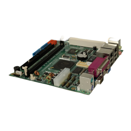
Supports two SATA channels with transfer rates up to 150Mb/s 1.2 KINO-LX Overview Figure 1-1: KINO-LX Overview 1.2.1 KINO-LX Connectors The KINO-LX has the following connectors onboard: 1 x 184-pin DDR DIMM socket 1 x AT/ATX power connector 1 x CD-IN connector... - Page 18 4 x RS-232 serial port connectors 1 x RS-232/422/485 serial port connector 2 x SATA connectors The KINO-LX has the following connectors on the board rear panel: 1 x Audio connector (two audio jacks) 2 x Ethernet connectors 2 x PS/2 keyboard/mouse connectors...
-
Page 19: Technical Specifications
KINO-LX Motherboard 1.2.2 Technical Specifications KINO-LX technical specifications are listed in Table 1-1. Detailed descriptions of each specification can be found in Chapter 2. SPECIFICATION DESCRIPTION CPUs Supported AMD ™ Geode ™ LX 800 Cache Memory 64K I/ 64k D L1 cache, 128K L2 cache System Chipset AMD ™... -
Page 20: Table 1-1: Technical Specifications
KINO-LX Motherboard SPECIFICATION DESCRIPTION Physical Dimensions 170mm x 170mm Operating Temperature Minimum: 0ºC (32°F) - Maximum: 60°C (140°F) Operating Humidity Minimum: 5% - Maximum: 95% Weight Gross: 1.1Kg - Net: 500g Table 1-1: Technical Specifications Page 20 IEI ® Technology, Corp. -
Page 21: Detailed Specifications
KINO-LX Motherboard Chapter Detailed Specifications Page 21... -
Page 22: Cpu Support
KINO-LX Motherboard 2.1 CPU Support The KINO-LX has a preinstalled AMD LX 800 processor. Technical specifications for the AMD LX 800 processor are listed below: x86/x87-compatible core Processor frequency up to 500 MHZ 64K I/64K D L1 cache and 128K L2 cache Split I/D cache/TLB (Translation Look-Aside Buffer) 64-bit DDR Memory interface. - Page 23 KINO-LX Motherboard Technical specifications of the AMD Geode™ CS5536 chipset are listed below. For more information on these two chipsets please refer to the AMD website. GeodeLink™ Interface Unit: 64-bit, 66MHz operation PCI VSM (Virtual System Module) that makes the interface transparent to...
-
Page 24: Data Flow
KINO-LX Motherboard 2.2.1 Data Flow Figure 2-1 shows the data flow between the system chipset, the CPU and other I/O interfaces that can connect to the KINO-LX motherboard. Figure 2-1: Data Flow Block Diagram Page 24 IEI ® Technology, Corp. -
Page 25: Graphics Support
KINO-LX Motherboard 2.3 Graphics Support Table 2-1 lists the KINO-LX graphics processor features. Feature AMD Geode™ LX Processor Color Depth 8, 16, 32 bpp (A) RGB 4 and 8-bit indexed ROPs 256 (2-src, dest and pattern) BLT Buffers FIFOs in Graphics Processor... -
Page 26: Memory Support
KINO-LX Motherboard Feature AMD Geode™ LX Processor Variable Source Stride Variable Destination Stride Destination Write Bursting Selectable BLT Direction Vertical and Horizontal Alpha BLT Yes (constant α, α/pix, or sep. α channel) VGA Support Decodes VGA Register Pipeline Depth Unlimited... - Page 27 KINO-LX Motherboard Compatible with IBM PC AT disk drive systems Variable write pre-compensation with track selectable capability Support vertical recording format DMA enable logic 16-byte data FIFOs Support floppy disk drives and tape drives Detects all overrun and underrun conditions...
- Page 28 KINO-LX Motherboard Compatible with IBM parallel port Support PS/2 compatible bi-directional parallel port Support Enhanced Parallel Port (EPP) - Compatible with IEEE 1284 specification Support Extended Capabilities Port (ECP) - Compatible with IEEE 1284 specification Enhanced printer port back-drive current protection...
-
Page 29: Ethernet Controller
KINO-LX Motherboard Keyboard Wake-Up by programmable keys Mouse Wake-Up by programmable buttons On Now Wake-Up from all of the ACPI sleeping states (S1-S5) Hardware Monitor Functions Smart Fan control system, support SMART FANTM I - “Thermal CruiseTM” and “Speed CruiseTM” Mode , SMART FANTM III function... -
Page 30: Drive Interfaces
The KINO-LX can support the following drive interfaces. 2 x SATA drives 2 x IDE devices 1 x FDD 2.7.1 SATA Drive Interface The KINO-LX supports two, first generation SATA drives with transfer rates of up to 150Mb/s. Page 30 IEI ® Technology, Corp. -
Page 31: Ide Hdd Interface
KINO-LX Motherboard 2.7.2 IDE HDD Interface The KINO-LX system chipset IDE controller supports up to two HDDs with the following specifications: 100 MB/second IDE Controller in UDMA mode per the ATA-6 specification 2.7.3 Floppy Disk Drive (FDD) Interface The KINO-LX supports a single FDD. The following FDD formats are compatible with the board. - Page 32 KINO-LX Motherboard 12.288MHz BITCLK input can be consumed Integrated PCBEEP generator to save buzzer Interrupt capability Page registers and Analog Plug & Play Support of S/PDIF out is fully compliant with AC'97 rev2.3 specifications Three analog line-level stereo inputs with 5-bit volume control: LINE_IN, CD,...
-
Page 33: Real Time Clock
CPU, chipset, and battery voltage, +5V, and +12V CPU and board temperatures (by the corresponding embedded sensors) 2.12 BIOS The KINO-LX uses a licensed copy of Phoenix Award BIOS. The features of the flash BIOS used are listed below: SMIBIOS (DMI) compliant... -
Page 34: Power Consumption
KINO-LX Motherboard 2.14 Power Consumption Table 2-2 shows the power consumption parameters for the KINO-LX when an AMD LX-800 CPU is running with a 333 MHz, 256MB DDR RAM module. Voltage Current 1.45A +12V 0.08A Table 2-2: Power Consumption 2.15 PXE: Pre-Boot Execution Environment PXE is an open industry standard developed by a number of software and hardware vendors. -
Page 35: Packaged Contents And Optional Accessory Items
KINO-LX Motherboard 2.16 Packaged Contents and Optional Accessory Items 2.16.1 Package Contents When you unpack the KINO-LX motherboard, you should find the following components. 1 x KINO-LX single board computer 1 x Mini jumper pack 1 x ATA66/100 flat cable... - Page 36 KINO-LX Motherboard THIS PAGE IS INTENTIONALLY LEFT BLANK Page 36 IEI ® Technology, Corp.
-
Page 37: Connectors And Jumpers
KINO-LX Motherboard Chapter Connectors and Jumpers Page 37... -
Page 38: Peripheral Interface Connectors
Figure 3-1 shows the on-board peripheral connectors and on-board jumpers. Figure 3-1: Connector and Jumper Locations 3.1.2 Peripheral Interface Connectors Table 3-1 shows a list of the peripheral interface connectors on the KINO-LX. Detailed descriptions of these connectors can be found in Section 3.2. Page 38... -
Page 39: Table 3-1: Peripheral Interface Connectors
KINO-LX Motherboard Connector Type Label AT/ATX power connector 20-pin header CN19 CD-IN connector 4-pin header DIMM socket 184-pin socket CN22 5V Fan connector 3-pin box header CN23 12V Fan connector 3-pin header CN21 FDD connector 34-pin box header CN26 Front Panel connector... -
Page 40: External Peripheral Interface Connectors
KINO-LX Motherboard 3.1.3 External Peripheral Interface Connectors Table 3-2 lists the external peripheral interface connectors on the KINO-LX. Detailed descriptions of these connectors can be found in Section 3.3. Connector Type Label Audio connector 2 x audio jacks Ethernet and USB combo connector RJ-45 and USB 2.0 connectors... -
Page 41: Internal Peripheral Connectors
Internal peripheral connectors are found on the motherboard and are only accessible when the motherboard is outside of the chassis. This section has complete descriptions of all the internal peripheral connectors on the KINO-LX. 3.2.1 AT/ATX Power Connector CN Label:... -
Page 42: Table 3-4: At/Atx Power Connector Pinouts
KINO-LX Motherboard DESCRIPTION DESCRIPTION -12V PSON PW-OK +5VSB +12V Table 3-4: AT/ATX Power Connector Pinouts Page 42 IEI ® Technology, Corp. -
Page 43: Cd-In Connector
KINO-LX Motherboard 3.2.2 CD-IN Connector CN Label: CN Type: 4-pin header CN Location: See Figure 3-3 CN Pinouts: See Table 3-5 The CD-In connector connects to audio sources such as CD/DVD-ROM optical drives. Figure 3-3: CD-IN Connector Pinout Locations DESCRIPTION... -
Page 44: Fan Connector
KINO-LX Motherboard 3.2.3 5V Fan Connector CN Label: CN23 CN Type: 3-pin wafer CN Location: See Figure 3-4 CN Pinouts: See Table 3-6 The cooling fan connector provides a 5V current to a system cooling fan. The connector has a "rotation" pin to get rotation signals from fans and notify the system so the system BIOS can recognize the fan speed. -
Page 45: Fan Connector
KINO-LX Motherboard 3.2.4 12V Fan Connector CN Label: CN21 CN Type: 3-pin wafer CN Location: See Figure 3-5 CN Pinouts: See Table 3-7 The cooling fan connector provides a 12V, 500mA current to a system cooling fan. The connector has a "rotation" pin to get rotation signals from fans and notify the system so the system BIOS can recognize the fan speed. -
Page 46: Floppy Disk Connector
KINO-LX Motherboard 3.2.5 Floppy Disk Connector CN Label: CN26 CN Type: 34-pin box header CN Location: See Figure 3-6 CN Pinouts: See Table 3-8 The floppy disk connector connects to a floppy disk drive. Figure 3-6: FDD Pinout Locations Page 46... -
Page 47: Front Panel Connector
KINO-LX Motherboard DESCRIPTION DESCRIPTION DENSEL INDEX# MOA# DSA# DIR# STEP# WDATA# WGATE# TRACK0# RDATA# HEAD# DSKCHG# Table 3-8: FDD Connector Pinouts 3.2.6 Front Panel Connector CN Label: CN24 CN Type: 14-pin header (2x7 pins) CN Location: See Figure 3-7 CN Pinouts:... -
Page 48: Figure 3-7: Front Panel Connector Pinout Locations
KINO-LX Motherboard Power LED HDD LED Figure 3-7: Front Panel Connector Pinout Locations DESCRIPTION DESCRIPTION PWRLED+ Buzzer+(+5V) PWRLED- PWRBTN# Buzzer- HDDLED+ SYS_RST# HDDLED- Table 3-9: Front Panel Connector Pinouts Page 48 IEI ® Technology, Corp. -
Page 49: Gpio Connector
KINO-LX Motherboard 3.2.7 GPIO Connector CN Label: CN18 CN Type: 10-pin header (2x5 pins) CN Location: See Figure 3-8 CN Pinouts: See Table 3-10 The General Purpose Input Output (GPIO) connector can be connected to external I/O control devices including sensors, lights, alarms and switches. -
Page 50: Ide Connectors
40-pin header (2x20) CN Location: See Figure 3-9 CN Pinouts: See Table 3-11 Two 40-pin IDE device connectors on the KINO-LX motherboard supports connectivity to Ultra ATA/133 IDE devices with data transfer rates up to 133MB/s. Page 50 IEI ® Technology, Corp. -
Page 51: Figure 3-9: Ide Device Connector Locations
KINO-LX Motherboard Figure 3-9: IDE Device Connector Locations Page 51... -
Page 52: Table 3-11: Ide Connector Pinouts
KINO-LX Motherboard DESCRIPTION DESCRIPTION RESET# IOW# IOR# ACK# CABLEID CS0# CS1# ASP# Table 3-11: IDE Connector Pinouts Page 52 IEI ® Technology, Corp. -
Page 53: Inverter Power Connector
KINO-LX Motherboard 3.2.9 Inverter Power Connector CN Label: CN12 CN Type: 5-pin wafer CN Location: See Figure 3-10 CN Pinouts: See Table 3-12 The inverter connector is connected to the LCD backlight. Figure 3-10: Inverter Connector Locations DESCRIPTION ADJ (Def : GND) -
Page 54: Keyboard/Mouse Connector
KINO-LX Motherboard 3.2.10 Keyboard/Mouse Connector CN Label: CN Type: 6-pin wafer CN Location: See Figure 3-11 CN Pinouts: See Table 3-13 For alternative applications, an on board keyboard/mouse pin header connector is also available. Figure 3-11: Keyboard/Mouse Connector Location DESCRIPTION... -
Page 55: Lcd Lvds Connector
KINO-LX Motherboard 3.2.11 LCD LVDS Connector CN Label: CN13 CN Type: 20-pin crimp connector CN Location: See Figure 3-12 CN Pinouts: See Table 3-14 The LCD LVDS connector is connected to a LCD LVDS display device. Figure 3-12: LCD LVDS Connector Locations... -
Page 56: Table 3-14: Lcd Lvds Connector Pinouts
KINO-LX Motherboard DESCRIPTION DESCRIPTION CLK- CLK+ LCD_VCC LCD_VCC LCD_VCC LCD_VCC Table 3-14: LCD LVDS Connector Pinouts Page 56 IEI ® Technology, Corp. -
Page 57: Lcd Ttl Connector
KINO-LX Motherboard 3.2.12 LCD TTL Connector CN Label: CN11 CN Type: 40-pin crimp connector CN Location: See Figure 3-13 CN Pinouts: See Table 3-15 The LCD TTL connector is connected to a LCD TTL display device. Figure 3-13: LCD TTL Connector Locations... -
Page 58: Pci Slot
KINO-LX Motherboard DESCRIPTION DESCRIPTION LCD_VCC LCD_VCC LCD_VCC LCD_VCC VSYNC HSYNC LCD_EN DISP_EN Table 3-15: LCD TTL Connector Pinouts 3.2.13 PCI Slot CN Label: CN20 CN Type: PCI slot CN Location: See Figure 3-14 CN Pinouts: See Table 3-16 The PCI slot enables a PCI expansion module to be connected to the board. -
Page 59: Figure 3-14: Pci Slot Location
KINO-LX Motherboard Figure 3-14: PCI Slot Location DESCRIPTION DESCRIPTION TRST -12V +12V Page 59... - Page 60 KINO-LX Motherboard DESCRIPTION DESCRIPTION INTA INTC INTB INTD RESERVED3 PRSNT1 RESERVED1 RESERVED4 PRSNT2 3.3V_AUX RESERVED2 AD30 AD31 +3.3V AD29 AD28 AD26 AD27 AD25 AD24 +3.3V IDSEL C/BE3 +3.3V AD23 AD22 AD20 AD21 AD19 AD18 +3.3V AD16 AD17 +3.3V C/BE2 FRAME Page 60 IEI ®...
-
Page 61: Table 3-16: Pci Slot
KINO-LX Motherboard DESCRIPTION DESCRIPTION IRDY TRDY +3.3V DEVSEL STOP +3.3V LOCK SDONE PERR +3.3V SERR +3.3V AD15 C/BE1 +3.3V AD14 AD13 AD11 AD12 AD10 C/BE0 +3.3V +3.3V REQ64 ACK64 Table 3-16: PCI Slot Page 61... -
Page 62: Rs-232/422/485 Serial Port Connector
KINO-LX Motherboard 3.2.14 RS-232/422/485 Serial Port Connector CN Label: CN10 CN Type: 2x7 pin header CN Location: See Figure 3-15 CN Pinouts: See Table 3-17 The CN10 serial port connector connects to an RS-232 or RS-485 serial port devices. Figure 3-15: RS-232/422/485 Serial Port Connector Pinout Locations... -
Page 63: Com Serial Port Connector
KINO-LX Motherboard 3.2.15 RS-232 COM Serial Port Connector CN Label: COM3, COM4, COM5 and COM6 CN Type: 10-pin header (2x5) CN Location: See Figure 3-16 CN Pinouts: See Table 3-18 The COM3, COM4, COM5 and COM6 serial port connectors connect to RS-232 serial port devices. -
Page 64: Sata Drive Connectors
KINO-LX Motherboard DESCRIPTION DESCRIPTION Table 3-18: RS-232 Serial Port Connector Pinouts 3.2.16 SATA Drive Connectors CN Label: CN30 and CN31 CN Type: 1x7 pin SATA drive connectors CN Location: See Figure 3-17 CN Pinouts: See Table 3-19 The two SATA drive connectors are connected to two first generation SATA drives. First generation SATA drives transfer data at speeds as high as 150Mb/s. -
Page 65: External Peripheral Interface Connector Panel
3.3 External Peripheral Interface Connector Panel Figure 3-18 shows the KINO-LX external peripheral interface connector panel. The peripheral connectors are connected to external devices when the KINO-LX is installed in a chassis. The peripheral connectors on the panel are: 1 x PS/2 keyboard and mouse connector... -
Page 66: Keyboard/Mouse Connector
CN Type: Dual PS/2 CN Location: See Figure 3-18 (labeled number 1) CN Pinouts: See Figure 3-19 and Table 3-20 The KINO-LX keyboard and mouse connectors are standard PS/2 connectors. Figure 3-19: Keyboard/Mouse Connector Pinouts DESCRIPTION DESCRIPTION L_KDAT L_MDAT L_KCLK... -
Page 67: Serial Port Connector
See Figure 3-18 (labeled number 2) CN Pinouts: See Figure 3-20 and Table 3-21 The KINO-LX has an RS-232 serial port on the external peripheral interface connector panel. Figure 3-20: Serial Port Connector Serial port connector (COM1) pinouts are shown below. -
Page 68: Parallel Port Connector
See Figure 3-18 (labeled number 3) CN Pinouts: See Figure 3-21 and Table 3-22 The KINO-LX has one parallel port on the external peripheral interface connector panel to connect to a printer or other parallel communication devices. Figure 3-21 Parallel Port Connector Pinout Locations... -
Page 69: Vga Connector
KINO-LX Motherboard 3.3.4 VGA connector CN Label: CN Type: HD-D-sub 15 female connector CN Location: See Figure 3-18 (labeled number 4) CN Pinouts: See Figure 3-22 and Table 3-23 A 15-pin VGA connector connects to standard displays. Figure 3-22: VGA Connector... -
Page 70: Lan Connectors
CN Pinouts: See Table 3-24 The KINO-LX is equipped with two built-in GbE Ethernet controllers. The controllers can connect to the LAN through two RJ-45 LAN connectors. There are two LEDs on the connector indicating the status of LAN. The pin assignments are listed in the following... -
Page 71: Usb Connectors
USB port CN Location: See Figure 3-18 (labeled number 5 and 6) CN Pinouts: See Table 3-26 The KINO-LX has a four rear panel USB ports. These ports connect to both USB 2.0 and USB 1.1 devices. DESCRIPTION DESCRIPTION USBV3L 5V... -
Page 72: Audio Connector
KINO-LX Motherboard 3.3.7 Audio Connector CN Label: CN Type: 2 x audio jacks CN Location: See Figure 3-18 (labeled number 7) CN Pinouts: See Figure 3-24 Line Out port (Lime): Connects to a headphone or a speaker. With multi-channel configurations, this port can also connect to front speakers. -
Page 73: Installation
KINO-LX Motherboard Chapter Installation Page 73... -
Page 74: Anti-Static Precautions
4.1 Anti-static Precautions Electrostatic discharge (ESD) can cause serious damage to electronic components, including the KINO-LX. (Dry climates are especially susceptible to ESD.) It is therefore critical that whenever the KINO-LX (or any other electrical component) is handled, the following anti-static precautions are strictly adhered to. -
Page 75: Unpacking
PCB circuit, connector pins, or its components. 4.3 Unpacking NOTE: If any of the items listed below are missing when the KINO-LX is unpacked, do not proceed with the installation and contact the reseller or vendor motherboard was purchased from. 4.3.1 Unpacking Precautions Some components on KINO-LX are very sensitive to static electricity and can be damaged by a sudden rush of power. -
Page 76: Checklist
1 x Mini Jumper Pack 1 x Utility CD 1 x QIG If one or more of these items are missing, please contact the reseller or vendor KINO-LX was purchased from and do not proceed any further with the installation. 4.4 KINO-LX Motherboard Installation... -
Page 77: Preinstalled Components
CPU and DIMM modules 4.4.1 Preinstalled Components The components listed below are preinstalled on the KINO-LX. 4.4.2 Components to Install To install the KINO-LX, the following components must be installed or connected to the KINO-LX: DIMM modules Peripheral devices 4.4.3 DIMM Module Installation... -
Page 78: Peripheral Device Connection
KINO-LX Motherboard Step 2: Align the DIMM module with the DIMM socket making sure the matching pins are correctly aligned. Step 3: Insert the DIMM module slowly. Once it is correctly inserted, push down firmly. The white handles on either side of the socket move back up and lock the module into the socket. -
Page 79: Ide Disk Drive Connectors (Cn29 Primary, Cn28 Secondary)
KINO-LX Motherboard Quantity Type mini jumper pack ATA 66/100 HDD cable SATA cables SATA power cable Dual RS-232 cables Table 4-1: IEI Provided Cables 4.5.1 IDE Disk Drive Connectors (CN29 Primary, CN28 Secondary) The cable used to connect the CPU card to an IDE HDD is a standard 40-pin ATA66/100 flat cable. -
Page 80: Com3-Com6 Rs-232 Serial Port Installation
KINO-LX Motherboard NOTE: When two EIDE disk drives are connected together, back-end jumpers on the drives must be used to configure one drive as a master and the other as a slave. 4.5.2 COM3-COM6 RS-232 Serial Port Installation The cable used to connect the motherboard to an RS-232 serial port is a 10-pin header to male D-sub 9 connector. -
Page 81: Lcd Backlight Installation
KINO-LX Motherboard 4.5.4 LCD Backlight Installation To connect an LCD backlight (inverter) to the motherboard, follow the instructions below. Step 1: Connect the 5-pin connector end of the LCD backlight cable to the CN12 header on the motherboard. A keyed pin on the connector prevents it from being connected incorrectly.Step 0:... -
Page 82: Jumper Settings
OPEN a jumper means removing the plastic clip from a jumper. Before the KINO-LX is installed in the system, the jumpers must be set in accordance with the desired configuration. The KINO-LX motherboard has six on-board jumpers. Description... -
Page 83: Clear Cmos Jumper
Jumper Location: See Figure 4-3 If the KINO-LX fails to boot due to improper BIOS settings, use this connector to clear the CMOS data and reset the system BIOS information. To do this, use the jumper cap to close pins 2 and 3 for a few seconds then reinstall the jumper clip back to pins 1 and 2. -
Page 84: Lcd Voltage Select Jumper
KINO-LX Motherboard Clear CMOS DESCRIPTION Short 1 - 2 (Default) Keep CMOS Setup Short 2 - 3 Clear CMOS Setup Table 4-3: Clear CMOS Jumper Settings 4.6.2 LCD Voltage Select Jumper WARNING: Making the wrong setting on this jumper may cause irreparable damage to both the motherboard and the LCD screen connected to the on-board connector. -
Page 85: Com2 Rs-232/422/485 Select
KINO-LX Motherboard 4.6.3 COM2 RS-232/422/485 Select Jumper Label: Jumper Type: 6-pin header Jumper Settings: See Table 4-5 Jumper Location: See Figure 4-3 The RS-232/422/485 select jumper sets the communication protocol used by the second serial communications port (COM2) as RS-232, RS-422 or RS-485. -
Page 86: Lcd Clock Jumper
KINO-LX Motherboard DESCRIPTION COM1 RI Pin Use +12V COM1 RI Pin Use +5V COM1 RI Pin Use RI COM2 RI Pin Use +12V COM2 RI Pin Use +5V 8-10 COM2 RI Pin Use RI Table 4-6: COM2 Voltage Setup Jumper Settings 4.6.5 LCD Clock Jumper... -
Page 87: Chassis Installation
After the DIMM modules have been installed and after the internal peripheral connectors have been connected to the peripheral devices and the jumpers have been configured, the KINO-LX can be mounted into chassis. To mount a board into a chassis, please refer to the chassis user guide that came with the product. -
Page 88: Serial Connection
KINO-LX Motherboard 4.8.2 Serial Connection The external peripheral interface connector panel serial connector provides easy and quick access to external serial devices. 4.8.3 Parallel Connector The external parallel port connector connects to a printer. The parallel port interface can be re-assigned to LPT2 or LPT3 through the BIOS configuration utility. The default interrupt channel is IRQ7. -
Page 89: Bios Settings
KINO-LX Motherboard Chapter BIOS Settings Page 89... -
Page 90: Introduction
KINO-LX Motherboard 5.1 Introduction A licensed copy of Phoenix Award BIOS is preprogrammed into the ROM BIOS. The BIOS setup program allows users to modify the basic system configuration. This chapter describes how to access the BIOS setup program and the configuration options that may be changed. -
Page 91: Using Setup
KINO-LX Motherboard 5.1.2 Using Setup Use the arrow keys to highlight items, press E to select, use the P NTER keys to change entries, press F1 for help and press E to quit. Navigation keys are shown below. Function Up arrow... -
Page 92: Unable To Reboot After Configuration Changes
KINO-LX Motherboard 5.1.4 Unable to Reboot After Configuration Changes If the system cannot be booted after changes are made, restore the CMOS defaults. The CPU card should come with a restore CMOS settings jumper. Refer to Section 4.5.1 for more information. -
Page 93: Load Fail-Safe Defaults
KINO-LX Motherboard The following menu options are seen in BIOS Menu 1. Standard CMOS Features: Changes the basic system configuration. Advanced BIOS Features: Changes the advanced system settings. Advanced Chipset Features: Changes the chipset configuration features. Integrated Peripherals: Changes the settings for integrated peripherals. -
Page 94: Standard Cmos Features
KINO-LX Motherboard press E in the “Enter Password: ” dialogue box, then press any key in the NTER “Password Disabled !!!” dialogue box. Save & Exit Setup Select this option to save any configuration changes made and exit the BIOS menus. -
Page 95: Ide Master And Ide Slave
KINO-LX Motherboard IDE Master and IDE Slave When entering setup, BIOS auto detects the presence of IDE devices. The Standard CMOS Features menu shows the status of the auto detected IDE devices. The following IDE devices are detected and shown in the Standard CMOS Features menu:... -
Page 96: Halt On [All, But Keyboard]
KINO-LX Motherboard Halt On [All, But Keyboard] Use the Halt On option to specify what errors detected during the power up process stop the system. All Errors Whenever BIOS detects a non-fatal error the system is stopped and the user prompted. -
Page 97: Ide Primary Master/Slave
KINO-LX Motherboard 5.2.1 IDE Primary Master/Slave Use the IDE Primary Master/Slave menu (BIOS Menu 3) to set or change the master/slave IDE configurations. BIOS Menu 3: IDE Primary Master IDE HDD Auto-Detection [Press Enter] Use the IDE HDD Auto-Detection option to enable BIOS to automatically detect the IDE settings. -
Page 98: Access Mode [Auto]
KINO-LX Motherboard None If no drives are connected to the IDE channel select this option. Once set, this channel becomes inaccessible and any drives attached to it are undetected. Auto (Default) Setting this option allows the device to be automatically detected by the BIOS. -
Page 99: Cylinder
KINO-LX Motherboard Cylinder The Cylinder specification indicates how many cylinders (tracks) are on the HDD installed in the system. Head The Head specification indicates how many logical heads are on the HDD installed in the system. Precomp The Precomp specification indicates on what track the write precompensation begins. -
Page 100: Advanced Bios Features
KINO-LX Motherboard 5.3 Advanced BIOS Features CPU and peripheral device configuration options are accessed in the Advanced BIOS Features menu (BIOS Menu 4). BIOS Menu 4: Advanced BIOS Features Virus Warning [Disabled] NOTE: Many disk diagnostic programs can cause the above warning message to appear when the program attempts to access the boot sector table. -
Page 101: Cpu Internal Cache [Enabled]
KINO-LX Motherboard Enabled Activates automatically when the system boots up causing a warning message to appear when anything attempts to access the boot sector or HDD partition table. Disabled (Default) No warning message appears when there is an attempt to access the boot sector or HDD partition table. -
Page 102: Boot Other Device [Enabled]
KINO-LX Motherboard First Boot Device [Default: Floppy] Second Boot Device [Default: HDD-0] Third Boot Device [Default: LS120] Using the default values, the system first looks for a floppy disk to boot from. If it cannot find a floppy disk, it boots from an HDD. If both The floppy and the HDD are unavailable, the system boots from a CDROM drive. -
Page 103: Swap Floppy Drive [Disabled]
KINO-LX Motherboard Swap Floppy Drive [Disabled] The Swap Floppy Drive option is effective only in systems with two floppy drives. Selecting Enabled assigns physical drive B to logical drive A, and physical drive A to logical drive B. Assigns physical drive B to logical drive A, and physical Enabled drive A to logical drive B. -
Page 104: Gate A20 Option [Fast]
KINO-LX Motherboard Gate A20 Option [Fast] Use the Gate A20 Option option to set if the keyboard controller or the chipset controls the Gate A20 switching. Normal The keyboard controller does the switching. Fast (Default) The chipset does the switching. -
Page 105: Typematic Delay (Msec) [250]
KINO-LX Motherboard 30 characters per second Typematic Delay (Msec) [250] The Typematic Rate option can only be configured if the Typematic Rate Setting is enabled. Use the Typematic Delay option to specify the delay time between when a key is first pressed and when the acceleration begins. -
Page 106: Os Select For Dram > 64Mb [Non-Os2]
KINO-LX Motherboard OS Select For DRAM > 64MB [Non-OS2] Use the OS Select For DRAM > 64MB option to specify the operating system. Enabled Specifies the operating system used as OS/2. Disabled (Default) Select this option when not using the OS/2 operating system. -
Page 107: Advanced Chipset Features
KINO-LX Motherboard 5.4 Advanced Chipset Features Use the Advanced Chipset Features menu (BIOS Menu 5) to change chipset configuration options. BIOS Menu 5: Advanced Chipset Features CPU Frequency [500MHz] Use the CPU Frequency option to set the CPU frequency. 500MHz (Default) Memory Frequency [Auto] Use the Memory Frequency option to set the frequency of the installed DRAM modules. -
Page 108: Cas Latency [Auto]
KINO-LX Motherboard CAS Latency [Auto] Use the CAS Latency Time option to set the Column Address Strobe (CAS) delay time. The CAS Latency Time options are: Auto (Default) 1.5 nanoseconds 2.0 nanoseconds 2.5 nanoseconds 3.0 nanoseconds 3.5 nanoseconds Interleave Select [LOI] Use the Interleave Select option to specify how the cache memory is interleaved. -
Page 109: Flat Panel Configuration
KINO-LX Motherboard CRT (Default) Panel & CRT Flat Panel Configuration [Press Enter] Use the Flat Panel Configuration option to open the Flat Panel Configuration menu. The Flat Panel Configuration options are shown in Section 5.4.1. OnBoard Audio [Enabled] Use the OnBoard Audio option to enable or disable the onboard codec. -
Page 110: Flat Panel Type [Auto]
KINO-LX Motherboard Flat Panel Type [Auto] Use the Flat Panel Type option to specify the type of flat panel screen connected to the system. Specifies the system is connected to a TFT display. LVDS Specifies the system is connected to an LVDS display. -
Page 111: Refresh Rate [60Hz]
KINO-LX Motherboard Refresh Rate [60Hz] The Refresh Rate option can only be configured if the Flat Panel Type option is not set to Auto. Use the Refresh Rate option to set the screen refresh rate required by the panel connected to the system. Check the documentation that came with the panel before setting this option. -
Page 112: Shfclk Active Period [Free Running]
KINO-LX Motherboard SHFCLK Active Period [Free Running] Use the SHFCLK Active Period option to set the SHFCLK. The SHFCLK Active Period options are: Active Only Free running (Default) LP Active Period [Free Running] Use the LP Active Period option to set the LDE/MOD signal to the panel. The LP Active... -
Page 113: Integrated Peripherals
KINO-LX Motherboard 5.5 Integrated Peripherals Use the Integrated Peripherals menu (BIOS Menu 7) to change the configuration options for the attached peripheral devices. BIOS Menu 7: Integrated Peripherals On-Chip IDE Channel 1 [Enabled] The On-Chip IDE Channel 1 option is enabled and is NOT user configurable. -
Page 114: Ide Udma [Auto]
KINO-LX Motherboard Mode 0 PIO mode 0 selected with a maximum transfer rate of 3.3MBps. Mode 1 PIO mode 1 selected with a maximum transfer rate of 5.2MBps. Mode 2 PIO mode 2 selected with a maximum transfer rate of 8.3MBps. -
Page 115: Onboard Fdc Controller [Enabled]
KINO-LX Motherboard Disabled Block mode is not supported. Enabled (Default) Block mode is supported. Onboard FDC Controller [Enabled] Use the Onboard FDC Controller option to enable or disable the onboard floppy controller. If the system is not connected to a floppy disk or uses an adapter for the FDD, this option can be disabled. -
Page 116: Onboard Serial Port 2 [2F8/Irq3]
KINO-LX Motherboard Onboard Serial Port 2 [2F8/IRQ3] Use the Onboard Serial Port 2 option to select the I/O address and IRQ for the onboard serial port 2. The serial port can be disabled or the I/O address and the IRQ can be automatically selected by the BIOS. -
Page 117: Onboard Parallel Port [378/Irq7]
KINO-LX Motherboard Onboard Parallel Port [378/IRQ7] Use the Onboard Parallel Port option to specify a logical LPT port address and corresponding interrupt for the physical parallel port. The Onboard Parallel Port options are: Disabled 378/IRQ7 (Default) 278/IRQ5 3BC/IRQ7 Parallel Port Mode [SPP] Use the Parallel Port Mode option to select parallel port operation mode. -
Page 118: Epp Mode Select [Epp1.7]
KINO-LX Motherboard x EPP Mode Select [EPP1.7] The EPP Mode Select option is only available if the Parallel Port Mode option is set to EPP mode. Use the EPP Mode Select option to select the parallel port mode standard for the parallel port. -
Page 119: Power Management Setup
KINO-LX Motherboard 5.6 Power Management Setup Use the Power Management Setup menu (BIOS Menu 8) to set the BIOS power management and saving features. BIOS Menu 8: Power Management Setup x ACPI Function [Disabled] The ACPI Function is enabled when the Power Management option is set to ACPI;... -
Page 120: Power Management [Acpi]
KINO-LX Motherboard Power Management [ACPI] Use the Power Management option to set the power management type used by the system. Disabled All power management options are turned off. The only user configurable options are the power button and alarm settings. -
Page 121: Suspend Mode [Disabled]
KINO-LX Motherboard x Suspend Mode [Disabled] The Suspend Mode option can only be selected if the Power Management option is set to Legacy. The Suspend Mode specifies the amount of time the system can be inactive before the system enters suspend mode. The Suspend Mode options are:... -
Page 122: Pnp/Pci Configurations
KINO-LX Motherboard 5.7 PnP/PCI Configurations Use the PnP/PCI Configurations menu (BIOS Menu 9) to set the plug and play, and PCI options. BIOS Menu 9: PnP/PCI Configurations PNP OS Installed [No] The PNP OS Installed option determines whether the Plug and Play devices connected to the system are configured by the operating system or the BIOS. -
Page 123: Resources Controlled By [Auto (Escd)]
KINO-LX Motherboard Disabled (Default) ESCD will not be reconfigured Enabled ESCD will be reconfigured after you exit setup Resources Controlled By [Auto (ESCD)] Use the Resources Controlled By option to either manually configure all the boot and plug and play devices, or allow BIOS to configure these devices automatically. If BIOS is allowed to configure the devices automatically IRQs, DMA and memory base address fields cannot be set manually. -
Page 124: Memory Resources [Press Enter]
KINO-LX Motherboard The IRQ Resources menu has the following options: IRQ-3 assigned to IRQ-4 assigned to IRQ-5 assigned to IRQ-7 assigned to IRQ-10 assigned to IRQ-11 assigned to The above options all have the following default options. (Default) The IRQ is assigned to legacy ISA for devices compliant... -
Page 125: Reserved Memory Base [N/A]
KINO-LX Motherboard BIOS Menu 11: Memory Resources The menu has two configurable options: Reserved Memory Base Reserved Memory Length Reserved Memory Base [N/A] The Reserved Memory Base option specifies the base address for the peripheral device. The Reserved Memory Base options are:... -
Page 126: Pc Health Status
KINO-LX Motherboard x Reserved Memory Length [8K] The Reserved Memory Length option can only be accessed if the Reserved Memory Base option is not set to N/A. The Reserved Memory Length specifies the amount of memory reserved for the peripheral device. The Reserved Memory Length options: 8K (Default) 5.8 PC Health Status... -
Page 127: Cpu Warning Temperature [Disabled]
KINO-LX Motherboard 60°C/140°F (Default) 65°C/149°F 70°C/158°F Disabled CPU Warning Temperature [Disabled] Use the CPU Warning Temperature option to specify a CPU operating temperature threshold that, when reached, generates a warning signal. Disabled (Default) 50°C/122°F 53°C/127°F 56°C/133°F 60°C/140°F 63°C/145°F 66°C/151°F 70°C/158°F... -
Page 128: Voltages
KINO-LX Motherboard Voltages The following voltages are monitored: Vcore VccMem +3.3 V +5 V +12 V VBAT (V) Page 128 IEI ® Technology, Corp. -
Page 129: Driver Installation
KINO-LX Motherboard Chapter Driver Installation Page 129... -
Page 130: Available Software Drivers
All five drivers can be found on the CD that came with the CPU card. To install the drivers please follow the instructions in the sections below. Insert the CD into the system that contains the KINO-LX CPU card. NOTE: If your system does not run the "autorun"... -
Page 131: Figure 6-1: Amd Lx/Gx Cd Main Menu
KINO-LX Motherboard Figure 6-1: AMD LX/GX CD Main Menu Step 2: A window appears listing the drivers available for installation (Figure 6-2). Page 131... -
Page 132: Figure 6-2: Amd Lx/Gx Cd Driver Menu
Select any item from the list to view more information on the driver installation, or select Manual to navigate to the KINO-LX user manual. Step 0: The following sections fully describe the driver installation procedures for the KINO-LX CPU card. Page 132... -
Page 133: Vga Driver
KINO-LX Motherboard 6.2 VGA Driver To install the VGA driver please follow the steps below. Step 1: Open Windows Control Panel (Figure 6-3). Figure 6-3: Access Windows Control Panel Step 2: Double click the System icon (Figure 6-4). Page 133... -
Page 134: Figure 6-4: Double Click The System Icon
KINO-LX Motherboard Figure 6-4: Double Click the System Icon Step 3: Double click the Device Manager tab (Figure 6-5). Figure 6-5: Double Click the Device Manager Tab Step 4: A list of system hardware devices appears (Figure 6-6). Page 134... -
Page 135: Figure 6-6: Device Manager List
KINO-LX Motherboard Figure 6-6: Device Manager List Step 5: Expand the Display Adapters category (Figure 6-7). Right click the adapter and select Properties. NOTE: Display Adapters category available, navigate X:\VGA\LX800\XP\VGA 2.01.05 (where X:\ is the system CD drive) and read the ReleaseNotes.txt file for further information on installing the VGA driver. -
Page 136: Figure 6-7: Expand The Display Adapters Category
KINO-LX Motherboard Figure 6-7: Expand the Display Adapters Category Step 6: From the Driver tab of the Properties window, click Update Driver (Figure 6-8) or, click Reinstall Driver if Update Driver is not seen. Page 136 IEI ® Technology, Corp. -
Page 137: Figure 6-8: Update Driver
KINO-LX Motherboard Figure 6-8: Update Driver Step 7: The Upgrade Device Driver Wizard appears (Figure 6-9). Click N continue. Page 137... -
Page 138: Figure 6-9: Upgrade Device Driver Wizard
KINO-LX Motherboard Figure 6-9: Upgrade Device Driver Wizard Step 8: The Install Hardware Device Driver screen appears (Figure 6-10). Select the Search for a suitable driver for my device radio button and click N continue. Page 138 IEI ® Technology, Corp. -
Page 139: Figure 6-10: Search For Suitable Driver
KINO-LX Motherboard Figure 6-10: Search for Suitable Driver Step 9: Select Specify a Location in the Locate Driver Files window (Figure 6-11). Click N to continue. Page 139... -
Page 140: Figure 6-11: Locate Driver Files
KINO-LX Motherboard Figure 6-11: Locate Driver Files Step 10: Click Browse and navigate to the X:\AMD\LX800\XP\VGA 2.01.05 directory, where “X:” is the system CD drive (Figure 6-12). Page 140 IEI ® Technology, Corp. -
Page 141: Figure 6-12: Location Browsing Window
KINO-LX Motherboard Figure 6-12: Location Browsing Window Step 11: Click OK to continue. Step 12: A driver files location menu window appears. Click N to continue. The driver is installed. Step 0: Page 141... -
Page 142: Audio Driver Installation
KINO-LX Motherboard 6.3 Audio Driver Installation To install the audio driver please follow the steps below. Step 1: Open Windows Control Panel (Figure 6-13). Figure 6-13: Access Windows Control Panel Step 2: Double click the System icon (Figure 6-14). Page 142... -
Page 143: Figure 6-14: Double Click The System Icon
KINO-LX Motherboard Figure 6-14: Double Click the System Icon Step 3: Double click the Device Manager tab (Figure 6-15). Figure 6-15: Double Click the Device Manager Tab Step 4: A list of system hardware devices appears (Figure 6-16). Page 143... -
Page 144: Figure 6-16: Device Manager List
KINO-LX Motherboard Figure 6-16: Device Manager List Step 5: Double click the listed device that has question marks next to it. (This means Windows does not recognize the device). Step 6: The Device Driver Wizard appears (Figure 6-17). Click N to continue. -
Page 145: Figure 6-17: Search For Suitable Driver
KINO-LX Motherboard Figure 6-17: Search for Suitable Driver Step 7: Select “Specify a Location” in the Locate Driver Files window (Figure 6-18). Click N to continue. Page 145... -
Page 146: Figure 6-18: Locate Driver Files
KINO-LX Motherboard Figure 6-18: Locate Driver Files Step 8: Select “X:\ Audio\GeodeLX_XP_XPe_WDM_Audio_v2.03.00” directory in the location browsing window, where “X:\” is the system CD drive (Figure 6-19). Page 146 IEI ® Technology, Corp. -
Page 147: Lan Driver
KINO-LX Motherboard Figure 6-19: Location Browsing Window Step 9: Click OK to continue. A driver files location menu window appears. Select the LXWDMAu.inf file and click O to continue. The driver is installed. Step 0: 6.4 LAN Driver To install the LAN driver, please follow the steps below. -
Page 148: Figure 6-21: Preparing Setup Screen
KINO-LX Motherboard Step 4: Double click the Setup program icon in Figure 6-20. Step 5: The Install Shield Wizard is prepared to guide the user through the rest of the process (Figure 6-21). Figure 6-21: Preparing Setup Screen Step 6: Once initialized, the Install Wizard welcome screen appears (Figure 6-22). -
Page 149: Figure 6-23: Installing Screen
KINO-LX Motherboard Step 7: Click N to continue the installation or C to stop the installation. ANCEL Step 8: The Install Wizard starts to install the LAN driver. Step 9: Once the installation is complete, the InstallShield Wizard Complete screen appears (Figure 6-23). -
Page 150: Sata/Raid Driver
KINO-LX Motherboard Figure 6-24: Restart the Computer 6.5 SATA/RAID Driver To install the ALi SATA/RAID driver, please follow the steps below. Step 1: Click SATA from the AMD LX/GX CD Driver Menu to open a window to the X:\ALi_SATA_M5283 (where X:\ is the system CD drive) folder on the driver Step 2: Locate the Setup program icon (Figure 6-25). -
Page 151: Figure 6-25: Locate The Setup Program Icon
KINO-LX Motherboard Figure 6-25: Locate the Setup Program Icon Step 3: The Install Shield Wizard (Figure 6-26) is prepared to guide the user through the rest of the process. Figure 6-26: Preparing Setup Screen Step 4: Once initialized, the Install Wizard welcome screen appears (Figure 6-27). -
Page 152: Figure 6-27: Install Wizard Welcome Screen
KINO-LX Motherboard Figure 6-27: Install Wizard Welcome Screen Step 5: Click N to continue the installation or C to stop the installation. ANCEL Step 6: The Install Wizard starts to install the driver (Figure 6-28). Page 152 IEI ® Technology, Corp. -
Page 153: Figure 6-28: Installing Screen
KINO-LX Motherboard Figure 6-28: Installing Screen Step 7: A “Digital Signal Not Found” screen appears (Figure 6-29). Click Y continue the installation process. Page 153... -
Page 154: Figure 6-29: Raid Driver Digital Signal
KINO-LX Motherboard Figure 6-29: RAID Driver Digital Signal Step 8: Once the installation is complete, the InstallShield Wizard Complete screen appears (Figure 6-30). Page 154 IEI ® Technology, Corp. -
Page 155: Figure 6-30: Installshield Wizard Complete Screen
KINO-LX Motherboard Figure 6-30: InstallShield Wizard Complete Screen Step 9: Once the installation process is complete, the computer may be restarted immediately or later. Select the preferred option and click F to complete the INISH installation process and exit the Install Shield Wizard. -
Page 156: Isa Driver
KINO-LX Motherboard 6.6 ISA Driver To install the IT8888 ISA Bridge driver please follow the steps below: Step 1: Open Windows Control Panel (Figure 6-31). Figure 6-31: Access Windows Control Panel Step 2: Double click the System icon (Figure 6-32). -
Page 157: Figure 6-32: Double Click The System Icon
KINO-LX Motherboard Figure 6-32: Double Click the System Icon Step 3: Double click the Device Manager tab (Figure 6-33). Figure 6-33: Double Click the Device Manager Tab Step 4: A list of system hardware devices appears (Figure 6-34). Page 157... -
Page 158: Figure 6-34: Device Manager List
KINO-LX Motherboard Figure 6-34: Device Manager List Step 5: Double click the listed device that has question marks next to it. (This means Windows does not recognize the device). Step 6: The Device Driver Wizard appears (Figure 6-35). Click N to continue. -
Page 159: Figure 6-35: Search For Suitable Driver
KINO-LX Motherboard Figure 6-35: Search for Suitable Driver Step 7: Select “Specify a Location” in the Locate Driver Files window (Figure 6-36). Click N to continue. Page 159... -
Page 160: Figure 6-36: Locate Driver Files
KINO-LX Motherboard Figure 6-36: Locate Driver Files Step 8: Select “X:\IT8888” directory in the location browsing window, where “X:\” is the system CD drive (Figure 6-37). Page 160 IEI ® Technology, Corp. -
Page 161: Figure 6-37: Location Browsing Window
KINO-LX Motherboard Figure 6-37: Location Browsing Window Click OK to continue. A driver files location menu window appears. Select the ite.inf file and click O to continue. The driver is installed. Step 0: Page 161... - Page 162 KINO-LX Motherboard THIS PAGE IS INTENTIONALLY LEFT BLANK Page 162 IEI ® Technology, Corp.
-
Page 163: Abios Menu Options
KINO-LX Motherboard Appendix BIOS Menu Options Page 163... -
Page 164: Bios Configuration Options
KINO-LX Motherboard A.1 BIOS Configuration Options Below is a list of BIOS configuration options described in Chapter 5. Load Fail-Safe Defaults ..................93 Load Optimized Defaults..................93 Set Supervisor Password ..................93 Set User Password ....................93 Save & Exit Setup ....................94 Exit Without Saving ....................94 Date [Day mm:dd:yyyy] ..................94... - Page 165 KINO-LX Motherboard Boot Other Device [Enabled] ................102 Swap Floppy Drive [Disabled] ................103 Boot Up Floppy Seek [Disabled] ............... 103 Boot Up Numlock Status [On] ................103 Gate A20 Option [Fast]..................104 Typematic Rate Setting [Disabled]..............104 Typematic Rate (Chars/sec) [6] ................. 104 Typematic Delay (Msec) [250]................
- Page 166 KINO-LX Motherboard IDE HDD Block Mode [Enabled] ................ 114 Onboard FDC Controller [Enabled]..............115 Onboard Serial Port 1 [3F8/IRQ4]..............115 Onboard Serial Port 2 [2F8/IRQ3]..............116 Onboard Serial Port # [XXX] ................116 Serial Port # Use IRQ [XXX] ................116 Onboard Parallel Port [378/IRQ7] ..............
-
Page 167: Bwatchdog Timer
KINO-LX Motherboard Appendix Watchdog Timer Page 167... - Page 168 KINO-LX Motherboard NOTE: The following discussion applies to DOS environment. IEI support is contacted or the IEI website visited for specific drivers for more sophisticated operating systems, e.g., Windows and Linux. The Watchdog Timer is provided to ensure that standalone systems can always recover from catastrophic conditions that cause the CPU to crash.
- Page 169 KINO-LX Motherboard NOTE: When exiting a program it is necessary to disable the Watchdog Timer, otherwise the system resets. Example program: ; INITIAL TIMER PERIOD COUNTER W_LOOP: AX, 6F02H ;setting the time-out value BL, 30 ;time-out value is 48 seconds ;...
- Page 170 KINO-LX Motherboard THIS PAGE IS INTENTIONALLY LEFT BLANK Page 170 IEI ® Technology, Corp.
-
Page 171: Caddress Mapping
KINO-LX Motherboard Appendix Address Mapping Page 171... -
Page 172: Io Address Map
KINO-LX Motherboard C.1 IO Address Map I/O address Description Range 000-01F DMA Controller 020-021 Interrupt Controller 040-043 System time 060-06F Keyboard Controller 070-07F System CMOS/Real time Clock 080-09F DMA Controller 0A0-0A1 Interrupt Controller 0C0-0DF DMA Controller 0F0-0FF Numeric data processor... -
Page 173: Irq Mapping Table
KINO-LX Motherboard C.3 IRQ Mapping Table IRQ0 System Timer IRQ8 RTC clock IRQ1 Keyboard IRQ9 ACPI IRQ2 Available IRQ10 IRQ3 COM2 IRQ11 LAN/USB2.0/SATA IRQ4 COM1 IRQ12 PS/2 mouse IRQ5 SMBus Controller IRQ13 IRQ6 IRQ14 Primary IDE IRQ7 Available IRQ15 Secondary IDE Table C-3: IRQ Mapping Table C.4 DMA Channel Assignments... - Page 174 KINO-LX Motherboard THIS PAGE IS INTENTIONALLY LEFT BLANK Page 174 IEI ® Technology, Corp.
-
Page 175: Dexternal Ac'97 Audio Codec
KINO-LX Motherboard Appendix External AC’97 Audio CODEC Page 175... -
Page 176: Introduction
KINO-LX Motherboard D.1 Introduction The motherboard comes with an onboard Realtek ALC203 CODEC. Realtek ALC203 is a 20-bit DAC and 18-bit ADC full-duplex AC'97 2.3 compatible stereo audio CODEC with a variable sampling rate. D.1.1 Accessing the AC’97 CODEC The CODEC is accessed through two phone jacks on the rear panel of the motherboard. -
Page 177: Sound Effect Configuration
KINO-LX Motherboard D.2 Sound Effect Configuration D.2.1 Accessing the Sound Effects Manager To access the Sound Effects Manager, please do the following: Step 1: Install the audio CODEC driver. Step 2: Click either: The Sound Effect Manager icon in the Notification Area of the system task bar (Figure D-2), or The Sound Effect Manager icon in the Control Panel (Figure D-3). -
Page 178: Sound Effect Manager Configuration Options
KINO-LX Motherboard Figure D-4: Sound Effects Manager (ALC203) NOTE: The Sound Effect Manager shown in Figure D-4 is for the RealTek ALC203 audio CODEC. Different CODECs may have different sound manager appearances. The following section describes the different configuration options in the Sound Effect Manager. - Page 179 KINO-LX Motherboard NOTE: The Karaoke Mode is configured in the Sound Effect menu. To access Karaoke configuration settings, click on the Sound Effect menu tab. Sound Effect Karaoke Mode Equalizer Speaker Configuration Speaker Test S/PDIF-In S/PDIF-Out Connector Sensing HRTF Demo...
- Page 180 KINO-LX Motherboard The Key adjustment up or down arrow icons enables users to define a key that fits a certain vocal range. Equalizer Selection:- Preset equalizer settings enable easy audio range settings. Ten frequency bands can be configured. Speaker Configuration:- Multi-channel speaker settings are configured in this menu.
-
Page 181: Eali ® Raid For Sata
KINO-LX Motherboard Appendix ® RAID for SATA Page 181... -
Page 182: Introduction
KINO-LX Motherboard E.1 Introduction The ALi M5283 SATA RAID chipset can control parallel ATA (PATA) and serial ATA (SATA) disks. The ALi controller supports PATA UDMA transfer mode up to mode 6 and SATA 1 disk drives. The ALi M5283 also has a cost-effective RAID functionality that can increase the data read/write speed and provide protection to data by distributing mirrored duplicates of data onto two disk drives (RAID 1). -
Page 183: Features And Benefits
KINO-LX Motherboard CAUTION! Do not accidentally disconnect the SATA drive cables. Carefully route the cables within the chassis to avoid system down time. E.2 Features and Benefits Supports RAID levels 0, 1, and JBOD Supports connectivity to two disk drives... - Page 184 KINO-LX Motherboard Step 3: Save and Exit BIOS. After the SATA ROM Support BIOS option is enabled, save and exit the BIOS. Step 4: Reboot the system. Reboot the system after saving and exiting the BIOS. Step 5: Press Ctrl-A. When the screen in Figure E-1 appears press Ctrl-A to enter the ALi RAID BIOS setup program.
-
Page 185: Raid Options
KINO-LX Motherboard Figure E-2: RAID BIOS Setup Utility Step 7: Configure the RAID settings. Use the RAID BIOS Setup Utility in Figure E-2 to configure the RAID array. Brief descriptions are given below. Step 8: Install the OS. After the RAID array has been configured (see below) install the OS. - Page 186 KINO-LX Motherboard Step 1: Select “Create RAID 0 Striping for Performance”. Use the arrow keys to highlight Create RAID0 Striping for Performance and press E . A flashing NTER ‘S’ appears on the Drive Menu where the member drives to be included in the RAID 0 array can be chosen.
- Page 187 KINO-LX Motherboard NOTE: 1. To reduce the chance of losing data, ALi imposes certain limitations on the RAID configuration options. PATA drives connected on the same IDE channel cannot be selected as the members of a RAID 0 array. Avoid mixing PATA and SATA disk drives in a RAID 0 array.
-
Page 188: Create Raid 1 Mirroring For Reliability
KINO-LX Motherboard E.4.2 Create RAID 1 Mirroring for Reliability WARNING! All data previously stored on the member drives of a RAID configuration is destroyed during the RAID initialization process. If “used” drives are used to create a RAID array, make sure the data has been moved or backed up before creating a RAID array out of the disk drives. - Page 189 KINO-LX Motherboard NOTE: To reduce the chance of losing data, ALi imposes certain limitations on the RAID configuration options. PATA drives connected on the same IDE channel cannot be selected as the members of a RAID 1 array. Avoid mixing PATA and SATA disk drives in a RAID 1 array.
-
Page 190: Create Jbod For Integrated Capacity
KINO-LX Motherboard E.4.3 Create JBOD for Integrated Capacity JBOD is defined as “Just a Bunch of Drives.” JBOD provides neither performance gains nor data redundancy. WARNING! All data previously stored on the member drives of a RAID configuration is destroyed during the RAID initialization process. If “used” drives are used to create a RAID array, make sure the data has been moved or backed up before creating a RAID array out of the disk drives. -
Page 191: Stripe Size
KINO-LX Motherboard NOTE: To reduce the chance of losing data, ALi imposes certain limitations on the RAID configuration options. Parallel-ATA drives connected on the same IDE channel cannot be selected as the members of a RAID1 array. Avoid mixing Parallel-ATA and Serial-ATA disk drives in a RAID1 array. -
Page 192: Delete All Raid Setting & Partition
KINO-LX Motherboard Step 2: Confirm Delete. The Data on RAID drives will be erased (Y/N) confirm box appears. Press Y.Step 0: E.4.6 Delete All RAID Setting & Partition WARNING! If a RAID configuration is deleted, all data previously stored on the member drives of the RAID configuration will also be deleted. -
Page 193: Select Boot Drive
KINO-LX Motherboard NOTE: A status bar will indicate the rebuild progress. Rebuild consumes considerable system resources and the time required for rebuilding a RAID array may vary depending on the size of stored data, disk drive capacity, and drive performance. - Page 194 KINO-LX Motherboard THIS PAGE IS INTENTIONALLY LEFT BLANK Page 194 IEI ® Technology, Corp.
-
Page 195: Index
KINO-LX Motherboard Index Page 195... - Page 196 KINO-LX Motherboard Drive Interfaces..........30 Driver Installation AC’97 Audio CODEC .......182 Audio Driver........148 Address Mapping Available Software Drivers ....136 1st MB Memory Address Map ..178,9 ISA Driver ........... 162 DMA Channel Assignments....180 LAN Driver .......... 153 IO Address Map........178 SATA RAID Driver.......
- Page 197 KINO-LX Motherboard 12V Fan Connector .......45 AT/ATX Power Connector .....41 Optional Accessory Items ......35 CD-IN Connector........43 Fan Connector........44 Floppy Disk Connector ......46 Package Contents........35 Front Panel Connector ......48 Peripheral Device Connection ....81 GPIO Connector........50 Physical Dimensions........20 IDE Connector........51 Power Consumption ........34 Inverter Power Connector .....54...
Need help?
Do you have a question about the KINO-LX and is the answer not in the manual?
Questions and answers