
Subscribe to Our Youtube Channel
Related Manuals for NXP Semiconductors FS4500


Summary of Contents for NXP Semiconductors FS4500
-
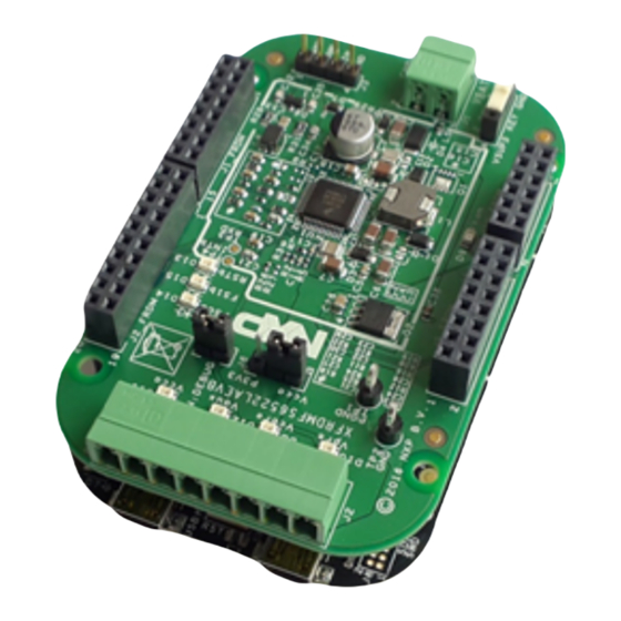
Page 1: Fig. 1. Frdmfs6523Caevm
FS4500/FS6500 evaluation boards KTFRDMFS4500-FS6500EVMUG Rev. 4.0 — 12 June 2017 User guide FRDMFS4503CAEVM, FRDMFS6523CAEVM and FRDMFS6522LAEVM evaluation boards aaa-025541 Figure 1. FRDMFS6523CAEVM... -
Page 2: Important Notice
NXP Semiconductors FS4500/FS6500 evaluation boards KTFRDMFS4500-FS6500EVMUG Important notice NXP provides the enclosed product(s) under the following conditions: This evaluation kit is intended for use of ENGINEERING DEVELOPMENT OR EVALUATION PURPOSES ONLY. It is provided as a sample IC pre-soldered to a printed circuit board to make it easier to access inputs, outputs, and supply terminals. -
Page 3: Getting Started
NXP Semiconductors FS4500/FS6500 evaluation boards KTFRDMFS4500-FS6500EVMUG Getting started 3.1 Jump start NXP’s analog product development boards provide an easy-to-use platform for evaluating NXP products. The boards support a range of analog, mixed-signal and power solutions. They incorporate monolithic ICs and system-in-package devices that use proven high-volume SMARTMOS technology. -
Page 4: Evm Overview
3.4 EVM overview The EVM contains two boards: • FRDMFS4503CAEVB or FRDMFS6523CAEVB or FRDMFS6522LAEVB: These are the evaluation boards available for the FS6500 / FS4500 SBC. The hardware is described in Section 4.5 "Getting to know the hardware". This document refers to these boards as EVBs. -
Page 5: Tab. 1. Evms Supporting The Fs45Xx/Fs65Xx Family
4.1 Board overview The FRDMFS4503CAEVB, FRDMFS6523CAEVB and FRDMFS6522LAEVB are hardware evaluation tools supporting system designs based on NXP’s FS4500 and FS6500 product families. The EVM allow testing the devices as an integral part of the overall system being developed. They provide access to all FS45xx and FS65xx functions (SPI, IOs) and support functional modes such as debug, normal, buck and boost. -
Page 6: Fig. 2. Frdmfs65/Frdmfs45 Block Diagram
NXP Semiconductors FS4500/FS6500 evaluation boards KTFRDMFS4500-FS6500EVMUG 4.3 Block diagram Vpre (switching) Vbat Vsup Vpre Filter Vcore Vcore Power Supply (switching) Connector J1_FRDM Vcca IO2_to_5 J10_FRDM MUX_OUT Vaux Vaux FS54XX VPRE Debug Debug VKAM FS65XX Vcore Vcca FS1b Vaux J9_FRDM CAN_5V... -
Page 7: Tab. 2. Fs45Xx/Fs65Xxfeatures
NXP Semiconductors FS4500/FS6500 evaluation boards KTFRDMFS4500-FS6500EVMUG 4.4 Device features TheFS65xx/FS45xx are multi-output power-regulating SMARTMOS devices aimed at the automotive market. They include CAN flexible data (FD) and/or LIN transceivers. Multiple switching and linear voltage regulators—including low-power mode (32 μA) —... -
Page 8: Tab. 3. Board Description
NXP Semiconductors FS4500/FS6500 evaluation boards KTFRDMFS4500-FS6500EVMUG aaa-025543 Figure 3. Evaluation board description Table 3. Board description Number Description connector - Use Phoenix connector to supply board FS45xx / FS65xx Ignition key - Ignition key from car Power supplies - Connector for power supplies (V CORE Power supplies LED - Visualizes regulator state (on or off). -
Page 9: Leds
NXP Semiconductors FS4500/FS6500 evaluation boards KTFRDMFS4500-FS6500EVMUG 4.5.1 LED display The board contains the following LEDs: aaa-025544 Figure 4. LEDs Table 4. LEDs Schematic label Name Color Description Green CORE CORE Vkam_IO5 Green Vkam_IO5 on Green Green Green RSTb Enabled when RSTB asserted (logic level = 0) -
Page 10: Tab. 5. Jumper Definitions
NXP Semiconductors FS4500/FS6500 evaluation boards KTFRDMFS4500-FS6500EVMUG 4.5.2 Jumper definitions Figure 5 shows the location of jumpers on the evaluation board. Table 5 describes the function and settings for each jumper. Default jumper settings are shown in bold text. aaa-025545 Figure 5. Jumpers Table 5. Jumper definitions... -
Page 11: Tab. 6. Test Point Definitions
NXP Semiconductors FS4500/FS6500 evaluation boards KTFRDMFS4500-FS6500EVMUG aaa-025546 Figure 6. Test points Table 6. Test point definitions Test point Signal name Description name Ground CAN receiver data. Logic level INTB INTB asserted (logic level = 0) CAN transmit data. Logic Level LIN receiver data. Logic level. -
Page 12: Tab. 7. Vbat Phoenix Connector (J1)
NXP Semiconductors FS4500/FS6500 evaluation boards KTFRDMFS4500-FS6500EVMUG aaa-025547 Figure 7. Connectors 4.5.4.1 V connector (J1) connects to the board through Phoenix connector (J1). Table 7. V Phoenix connector (J1) Pin number Connection Description Connects to V Ground Connects to ground 4.5.4.2 SPI connector (J2_FRDM) The Debug connector(J2_FRDM) gives access to the FS65xx main signal for debug or experimentation purposes. -
Page 13: Can And Lin Connector (J3)
NXP Semiconductors FS4500/FS6500 evaluation boards KTFRDMFS4500-FS6500EVMUG Pin number Connection Description FS0B Fail-safe 0. MOSI SPI Master Output Slave Input Not Connected MISO SPI Master Input Slave Output Not Connected SCLK SPI serial clock Not Connected Ground Not Connected Not Connected... -
Page 14: I/O Connector (J1_Frdm)
NXP Semiconductors FS4500/FS6500 evaluation boards KTFRDMFS4500-FS6500EVMUG Pin number Connection Description Not Connected Not Connected Not Connected Connects to ground Debug pin selection Connects to ground RSTB Reset, active low Not Connected 4.5.4.5 I/O connector (J1_FRDM) The I/O connector accesses the device under test (DUT) IO and V signals. -
Page 15: Kl25Z Adc Inputs (J10_Frdm)
NXP Semiconductors FS4500/FS6500 evaluation boards KTFRDMFS4500-FS6500EVMUG Pin number Connection Description auxiliary voltage regulator Ground voltage output CORE CORE Ground regulator output regulator Ground 4.5.4.7 KL25Z ADC inputs (J10_FRDM) The KL25Z ADCconnector (J10_FRDM) connects the FS6500 regulator outputs to the ADCs on the KL25Z. The regulator values can then be measured and displayed in FlexGUI. -
Page 16: Switches
NXP Semiconductors FS4500/FS6500 evaluation boards KTFRDMFS4500-FS6500EVMUG 4.5.5 Switches aaa-025548 Figure 8. Switches Table 14. SW1 Position Function Description Connection between Key input and ground Vsup3 Connection between Key input and Vsup3 FS4500/FS6500 evaluation boards All information provided in this document is subject to legal disclaimers. -
Page 17: Board Default Settings
NXP Semiconductors FS4500/FS6500 evaluation boards KTFRDMFS4500-FS6500EVMUG Board default settings 5.1 V and V setting and V are set by default, respectively to 3.3 V and 5.0 V. It’s possible to change that by modifying R26 or R27 (whichever is populated) according to... -
Page 18: Compensation Network
NXP Semiconductors FS4500/FS6500 evaluation boards KTFRDMFS4500-FS6500EVMUG • R42: populated • C8/C9/R4/D3/L2/C5/C7/R2/C11/R5/C17: DNP aaa-025550 Figure 11. V configuration CORE 5.2.2 Compensation network Both LDO and DC/DC voltage regulators use VCORE voltage feedback to control the output voltage (see Figure 12). For FS45xx devices using static (steady-state) LDO regulators, a simple resistor bridge (resistors R3 and R6) determines the feedback voltage. -
Page 19: Mcu Analog Input
NXP Semiconductors FS4500/FS6500 evaluation boards KTFRDMFS4500-FS6500EVMUG aaa-025552 Figure 12. FCRBM Resistor Bridge 5.2.4 MCU analog input To assure the complete isolation of analog signals connected from an external component to the MCU, remove input resistance as applicable for the following: • V tied to MCU through R83 •... -
Page 20: Configuring The Evm
NXP Semiconductors FS4500/FS6500 evaluation boards KTFRDMFS4500-FS6500EVMUG Configuring the EVM 6.1 Connecting the hardware The EVB can be connected to a PC through the FRDM-KL25Z board included with this EVM or any board with an MCU that supports SPI. A power supply with a typical value of 13.5 V must be connected to J1. - Page 21 NXP Semiconductors FS4500/FS6500 evaluation boards KTFRDMFS4500-FS6500EVMUG aaa-025554 Figure 13. Evaluation board hardware configuration The software is normally pre-loaded on the KL25Z. For future updates, the procedure for programming the KL25 is described in Section 8 "Appendix A: FRDM-KL25Z software loading". FS4500/FS6500 evaluation boards All information provided in this document is subject to legal disclaimers.
-
Page 22: Software
NXP Semiconductors FS4500/FS6500 evaluation boards KTFRDMFS4500-FS6500EVMUG Software The FRDMFS4503CAEVB/FRDMFS6523CAEVB/FRDMFS6522LAEVB boards must be plugged into a FRDM-KL25Z. Firmware controlling the communication with the FS45xx/FS65xx must be loaded onto the MCU. The procedure for loading the firmware is described in Section 8 "Appendix A: FRDM-KL25Z software loading". -
Page 23: Creating And Using A Register Configuration File
NXP Semiconductors FS4500/FS6500 evaluation boards KTFRDMFS4500-FS6500EVMUG 7.1 Creating and using a register configuration file Creating an Excel register configuration file allows the user to initialize the evaluation board MCU with a predefined set of register values. To create a register configuration file, do the following: 1. -
Page 24: Using The Flexgui
NXP Semiconductors FS4500/FS6500 evaluation boards KTFRDMFS4500-FS6500EVMUG aaa-025556 6. Send the register configuration file to the FS45xx/FS65xx by clicking the Send Sequence button. aaa-025645 7.2 Using the FlexGUI To start the FlexGUI, do the following: 1. Configure the hardware as described in Section 6.1 "Connecting the... - Page 25 NXP Semiconductors FS4500/FS6500 evaluation boards KTFRDMFS4500-FS6500EVMUG • Create an Excel file configured as shown in Table 15. For details on creating an Excel register configuration file, see Section 7.1 "Creating and using a register configuration file" Table 15. Use case register configuration Excel file example...
-
Page 26: Appendix A: Frdm-Kl25Z Software Loading
NXP Semiconductors FS4500/FS6500 evaluation boards KTFRDMFS4500-FS6500EVMUG aaa-025559 Appendix A: FRDM-KL25Z software loading The quick start package containing the latest firmware can be downloaded from the Downloads tab of the following webpage: http://www.nxp.com/FRDM-KL25Z Software loading for the FRDM-KL25Z consists of the following: •... -
Page 27: Programming The Frdm-Kl25Z
NXP Semiconductors FS4500/FS6500 evaluation boards KTFRDMFS4500-FS6500EVMUG aaa-025594 5. Disconnect the board. 8.2 Programming the FRDM-KL25Z The software bundle for FRDM_FS6500 includes a USBtest3.hex file that programs FRDM-KL25Z with the needed firmware. The procedure is as follows: 1. Connect USB (the one marked SDA). -
Page 28: Appendix B: Installing The Flexgui
NXP Semiconductors FS4500/FS6500 evaluation boards KTFRDMFS4500-FS6500EVMUG Appendix B: Installing the FlexGUI The FlexGUI graphical user interface provides a PC-based interface for accessing the evaluation board and exercising FS45xx/FS65xx functions. The GUI runs on any Windows 8, Windows 7 or Vista operating system. -
Page 29: Schematics, Board Layout And Bill Of Materials
NXP Semiconductors FS4500/FS6500 evaluation boards KTFRDMFS4500-FS6500EVMUG 10 Schematics, board layout and bill of materials Board schematics, board layout and bill of materials are available in the download tab of the Tool summary page for the associated board. See Section 11 "References"... -
Page 30: References
NXP Semiconductors FS4500/FS6500 evaluation boards KTFRDMFS4500-FS6500EVMUG 11 References The following URLs reference related NXP products and application solutions: NXP.com support pages Description https://www.nxp.com/webapp/Download? FS6500-FS4500 Datasheet colCode=FS6500-FS4500 AN5238 - Hardware design and Application note https://www.nxp.com/webapp/Download? product guidelines colCode=AN5238 AN4661 - Designing the Application note http://www.nxp.com/files/analog/doc/... -
Page 31: Revision History
NXP Semiconductors FS4500/FS6500 evaluation boards KTFRDMFS4500-FS6500EVMUG 13 Revision history Revision Date Description of changes 11/2016 • Initial release • Removed content, supporting data and external references for FRDMFS6522LAEVM and FRDMFS6522LAEVB in Section 3.1, Section 3.2, Section 3.4, Section 4.1, Table Section 4.2,... -
Page 32: Legal Information
Draft — The document is a draft version only. The content is still under and products using NXP Semiconductors products in order to avoid a internal review and subject to formal approval, which may result in default of the applications and the products or of the application or use by modifications or additions. -
Page 33: Table Of Contents
NXP Semiconductors FS4500/FS6500 evaluation boards KTFRDMFS4500-FS6500EVMUG Tables Tab. 1. EVMs supporting the FS45xx/FS65xx family ..5 Tab. 9. CAN & LINconnector (J3) ....... 13 Tab. 2. FS45xx/FS65xxfeatures ........7 Tab. 10. USB connector (J33) ........13 Tab. 3. Board description ..........8 Tab. - Page 34 NXP Semiconductors FS4500/FS6500 evaluation boards KTFRDMFS4500-FS6500EVMUG Contents FRDMFS4503CAEVM, FRDMFS6523CAEVM FRDMFS6522LAEVM evaluation boards ... 1 Important notice ..........2 Getting started ............ 3 Jump start ............3 Kit contents/packing list ........3 Required equipment .......... 3 EVM overview ............4 Board description ..........5 Board overview ..........5...
- Page 35 Mouser Electronics Authorized Distributor Click to View Pricing, Inventory, Delivery & Lifecycle Information: FRDMFS6522LAEVM...
Need help?
Do you have a question about the FS4500 and is the answer not in the manual?
Questions and answers