
Subscribe to Our Youtube Channel
Related Manuals for NXP Semiconductors QorIQ FRDM-LS1012A


Summary of Contents for NXP Semiconductors QorIQ FRDM-LS1012A
- Page 1 QorIQ FRDM-LS1012A Board Reference Manual Document Number: FRDM-LS1012ARM Rev. 3, 12/2016...
- Page 2 QorIQ FRDM-LS1012A Board Reference Manual, Rev. 3, 12/2016 NXP Semiconductors...
-
Page 3: Table Of Contents
Double data rate (DDR) memory............................18 Serializer/deserializer (SerDes)............................18 Ethernet controller................................18 2.7.1 SGMII ports............................... 18 Audio interface................................21 USB interface .................................21 2.10 I2C ports..................................22 2.10.1 I2C devices and addresses..........................22 2.11 QSPI interface.................................23 2.12 SPI interface..................................23 QorIQ FRDM-LS1012A Board Reference Manual, Rev. 3, 12/2016 NXP Semiconductors... - Page 4 Section number Title Page 2.13 Ardiuno................................... 24 2.14 JTAG port..................................24 2.14.1 CMSIS-DAP..............................24 2.15 GPIO pins..................................25 2.16 Temperature ................................... 26 2.17 Power-monitoring LEDs..............................26 2.18 Revision control................................26 QorIQ FRDM-LS1012A Board Reference Manual, Rev. 3, 12/2016 NXP Semiconductors...
-
Page 5: Introduction
Chapter 1 Overview 1.1 Introduction The QorIQ FRDM-LS1012A board is an ultra-low-cost development platform for LS1012A. The board provides connectivity support for SPI, UART, and I2C based Arduino and freedom boards. Also, the FRDM-LS1012A supports the DDR3L memory, two 1 Gbit/s Ethernet ports, one USB 3.0 5 Gbit/s port, and the Audio in and out interface. -
Page 6: Acronyms And Abbreviations
Power supply Power supply unit Reset Configuration Word Serial data line SerDes Serializer/deserializer used to interface with serial interfaces, such as PCIe, SGMII, and SATA Table continues on the next page... QorIQ FRDM-LS1012A Board Reference Manual, Rev. 3, 12/2016 NXP Semiconductors... -
Page 7: Frdm-Ls1012A Features
• 25 MHz for audio codec from LS1012A CLKOUT • 8 MHz Crystal for K20 • 24 MHz for SC16IS740IPW SPI to Dual UART bridge Table continues on the next page... QorIQ FRDM-LS1012A Board Reference Manual, Rev. 3, 12/2016 NXP Semiconductors... -
Page 8: Frdm-Ls1012A Block Diagram
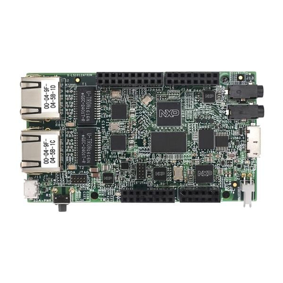
On Board Power Supply LED’s 5V from USB (Debug port) (PG & RESET) Figure 1-1. FRDM-LS1012A block diagram 1.6 FRDM-LS1012A top view The following figure shows the top view of the FRDM-LS1012A. QorIQ FRDM-LS1012A Board Reference Manual, Rev. 3, 12/2016 NXP Semiconductors... - Page 9 ARM JTAG header (J9) USB 2.0 debug/UART connector (J11) PORST LED (D3) Reset switch (SW1) K20 JTAG SDA_LED (D1) Header for header (J10) USB power (J12) Figure 1-2. FRDM-LS1012A top view QorIQ FRDM-LS1012A Board Reference Manual, Rev. 3, 12/2016 NXP Semiconductors...
- Page 10 FRDM-LS1012A top view QorIQ FRDM-LS1012A Board Reference Manual, Rev. 3, 12/2016 NXP Semiconductors...
-
Page 11: Ls1012Afrdm Functional Description
The FRDM-LS1012A power supplies (PS) provide all the voltages necessary for the correct operation of the LS1012A processor, DDR3L, QSPI memory, and other onboard peripherals. The following figure shows the FRDM-LS1012A power supplies. QorIQ FRDM-LS1012A Board Reference Manual, Rev. 3, 12/2016 NXP Semiconductors... -
Page 12: Primary Power Supply
The total power required from USB port depends on devices used by an application. Refer to the following table for an estimated power required by each of the board interfaces. QorIQ FRDM-LS1012A Board Reference Manual, Rev. 3, 12/2016 NXP Semiconductors... -
Page 13: Frdm-Ls1012A Power Supply Delivery System
3.3 V at 0.8 A power supply for: • secondary regulator VR5100, • onboard SGMII PHYs, • and LS1012A supplies: EVDD and USB_HVDD VCC_ VCC_0V9 MC34VR5100A1EP Power supply for: • LS1012A power supplies VCC_1V8 VCC_1V35 QorIQ FRDM-LS1012A Board Reference Manual, Rev. 3, 12/2016 NXP Semiconductors... -
Page 14: Power-On
(AVDD_PLAT, AVDD_CGA1, TH_VDD, AVDD_SD1_PLL1, AVDD_SD1_PLL2, OVDD, XOSC_OVDD, USB_SVDD, USB_SDVDD, G1VDD, VREF, SVDD, and XVDD) • LS1012A core supplies: VDD Red LED (D3) • Reset LED is deasserted. 2.2.4 Voltage regulation QorIQ FRDM-LS1012A Board Reference Manual, Rev. 3, 12/2016 NXP Semiconductors... -
Page 15: Reset And Configuration Signals
EVDD 3.3 V MC34713 VCC_POVDD 1.8 V VR5100 LDO1 Powers the LS1012A SFP fuse programming voltage 2.3 Reset and configuration signals The reset sequence can be triggered from various sources. QorIQ FRDM-LS1012A Board Reference Manual, Rev. 3, 12/2016 NXP Semiconductors... - Page 16 PORCFG through the resistor mount option. Mount the resistors to drive the corresponding PORCFG as low in Table 2-5. Table 2-5. Configuration signals Configuration signal Nets sampled Components on board Default state CFG_RCW_SRC1 CLK_OUT QorIQ FRDM-LS1012A Board Reference Manual, Rev. 3, 12/2016 NXP Semiconductors...
-
Page 17: Clocks
• Input/Output clock frequency up to codec 200 MHz 8MHz XTAL for K20 8 MHz Crystal clock for K20 Crystal BRDG_CLKIN_24MHz 24 MHz Clock for SC16IS740IPW Oscillator SPI to Dual UART bridge QorIQ FRDM-LS1012A Board Reference Manual, Rev. 3, 12/2016 NXP Semiconductors... -
Page 18: Double Data Rate (Ddr) Memory
RTL8211FS-CG • SGMII 1G PHY 1.25 Gbit/s 2.7 Ethernet controller The LS1012A processor supports two Ethernet MACs, which connect to the onboard PHYs using the SGMII protocols. 2.7.1 SGMII ports QorIQ FRDM-LS1012A Board Reference Manual, Rev. 3, 12/2016 NXP Semiconductors... - Page 19 MODE: SGMII EM1_MDC MDIO EM1_MDIO 1.8V 3.3V VSEL/ GPIO_1[13] Voltage Translator REG_OUT 3V3_RST_B DVDD10 PHYRSTB 0 ohm AVDD10 AVDD33 4.7K DVDD33 INTB DVDD_RG 4.7K PMEB Figure 2-5. SGMII PHY1 QorIQ FRDM-LS1012A Board Reference Manual, Rev. 3, 12/2016 NXP Semiconductors...
- Page 20 PHY Addr = 0b00001 (for SGMII PHY2) CFG_LDO[1:0] = 10 External power voltage selections for IO pads (1.8 V) CFG_MODE[2:0] = 011 UTP > SGMII Table continues on the next page... QorIQ FRDM-LS1012A Board Reference Manual, Rev. 3, 12/2016 NXP Semiconductors...
-
Page 21: Audio Interface
• a 2-pin header (J12) to provide 5 V at 1 A power supply to the USB 2.0/3.0 port The following figure shows the USB 2.0/3.0 PHY architecture on the FRDM-LS1012A. QorIQ FRDM-LS1012A Board Reference Manual, Rev. 3, 12/2016 NXP Semiconductors... -
Page 22: I2C Ports
LS1012A 1.8 V to 3.3 V signals for the I2C devices, on Arduino/ Freedom expansion connectors. • The I2C1 bus has one possible master - LS1012A processor. 2.10.1 I C devices and addresses QorIQ FRDM-LS1012A Board Reference Manual, Rev. 3, 12/2016 NXP Semiconductors... -
Page 23: Qspi Interface
The UART interface connects to devices on Arduino/Freedom expansion connectors. • SPI bus interface can also connect to the Ardiuno shield, J2, via level translators. The following table describes the SPI devices used on the FRDM-LS1012A board. QorIQ FRDM-LS1012A Board Reference Manual, Rev. 3, 12/2016 NXP Semiconductors... -
Page 24: Ardiuno
This section describes the MBED circuit on the LS1012AFRDM. MBED is an open standard serial and debug adapter. It bridges serial and debug communications between a USB host and an embedded target processor, as shown in the figure below. QorIQ FRDM-LS1012A Board Reference Manual, Rev. 3, 12/2016 NXP Semiconductors... -
Page 25: Gpio Pins
Connects LS1012A to Arduino EC1_TXD3 DUT_GPIO_2[2] Connects LS1012A to Arduino through 1.8 V to 3.3 V translators EC1_TXD2 DUT_GPIO_2[3] Connects LS1012A to Arduino through 1.8 V to 3.3 V translators QorIQ FRDM-LS1012A Board Reference Manual, Rev. 3, 12/2016 NXP Semiconductors... -
Page 26: Temperature
The GPIO2[14], GPIO2[12], and GPIO1[11] are used to determine the board revision of FRDM-LS1012A. The following table explains the board revisions. Table 2-13. Revision control {GPIO2[14], GPIO2 [12], GPIO2[11] } VERSION Rev B Rev C QorIQ FRDM-LS1012A Board Reference Manual, Rev. 3, 12/2016 NXP Semiconductors... - Page 27 FRDM-LS1012A top-side view • FRDM-LS1012A bottom-side view A.1 FRDM-LS1012A top-side view NOTE For a clear view of the board top-side view, please zoom-in on the Figure. Figure A-1. FRDM-LS1012A top-side view QorIQ FRDM-LS1012A Board Reference Manual, Rev. 3, 12/2016 NXP Semiconductors...
- Page 28 FRDM-LS1012A bottom-side view A.2 FRDM-LS1012A bottom-side view NOTE For a clear view of the board bottom-side view, please zoom-in on the Figure. Figure A-2. FRDM-LS1012A bottom-side view QorIQ FRDM-LS1012A Board Reference Manual, Rev. 3, 12/2016 NXP Semiconductors...
- Page 29 Added details for GPIOs used to determine board revision FRDM-LS1012A board drawings Updated top-side and bottom-side assembly drawings GPIO pins Updated Table 2-11 • Remove "SDHC1_VSEL" row • Remove translators details from SDHC1 rows QorIQ FRDM-LS1012A Board Reference Manual, Rev. 3, 12/2016 NXP Semiconductors...
- Page 30 QorIQ FRDM-LS1012A Board Reference Manual, Rev. 3, 12/2016 NXP Semiconductors...
- Page 31 How to Reach Us: Information in this document is provided solely to enable system and software implementers to use NXP products. There are no express or implied copyright Home Page: licenses granted hereunder to design or fabricate any integrated circuits based nxp.com on the information in this document.
Need help?
Do you have a question about the QorIQ FRDM-LS1012A and is the answer not in the manual?
Questions and answers