Table of Contents
Advertisement
Quick Links
OPERATION AND MAINTENANCE MANUAL FOR
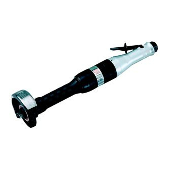
SERIES 61H HORIZONTAL AIR GRINDERS
Series 61H Horizontal Air Grinders are designed for heavy duty grinding in confined
areas such as small castings or inside larger castings.
Ingersoll–Rand is not responsible for customer modification of tools for applications on
which Ingersoll–Rand was not consulted.
IMPORTANT SAFETY INFORMATION ENCLOSED.
READ THIS MANUAL BEFORE OPERATING TOOL.
IT IS THE RESPONSIBILITY OF THE EMPLOYER TO PLACE THE INFORMATION
IN THIS MANUAL INTO THE HANDS OF THE OPERATOR.
FAILURE TO OBSERVE THE FOLLOWING WARNINGS COULD RESULT IN INJURY.
PLACING TOOL IN SERVICE
•
Always operate, inspect and maintain this tool in
accordance with American National Standards
Institute Safety Code for Portable Air Tools
(ANSI B186.1).
•
For safety, top performance, and maximum
durability of parts, operate this tool at 90 psig
(6.2 bar/620 kPa) maximum air pressure at the inlet
with 1/2" (13 mm) inside diameter air supply hose.
•
Always turn off the air supply and disconnect the
air supply hose before installing, removing or
adjusting any accessory on this tool, or before
performing any maintenance on this tool.
•
Do not use damaged, frayed or deteriorated air
hoses and fittings.
•
Be sure all hoses and fittings are the correct size
and are tightly secured. See Dwg. TPD905–1 for a
typical piping arrangement.
•
Always use clean, dry air at 90 psig (6.2 bar/
620 kPa) maximum air pressure. Dust, corrosive
fumes and/or excessive moisture can ruin the motor
of an air tool.
•
Do not lubricate tools with flammable or volatile
liquids such as kerosene, diesel or jet fuel.
•
Do not remove any labels. Replace any damaged
label.
The use of other than genuine Ingersoll–Rand replacement parts may result in safety hazards, decreased tool
performance, and increased maintenance, and may invalidate all warranties.
Repairs should be made only by authorized trained personnel. Consult your nearest Ingersoll–Rand Authorized
Servicenter.
Refer All Communications to the Nearest
Ingersoll–Rand Office or Distributor.
Ingersoll–Rand Company 2000
Printed in U.S.A.
03534948
USING THE TOOL
•
Always wear eye protection when operating or
performing maintenance on this tool.
•
Always wear hearing protection when operating
this tool.
•
Keep hands, loose clothing and long hair away from
rotating end of tool.
•
Anticipate and be alert for sudden changes in
motion during start up and operation of any power
tool.
•
Keep body stance balanced and firm. Do not
overreach when operating this tool. High reaction
torques can occur at or below the recommended air
pressure.
•
Tool accessories may continue to rotate briefly after
throttle is released.
•
Air powered tools can vibrate in use. Vibration,
repetitive motions or uncomfortable positions may
be harmful to your hands and arms. Stop using any
tool if discomfort, tingling feeling or pain occurs.
Seek medical advice before resuming use.
•
Use accessories recommended by Ingersoll–Rand.
•
This tool is not designed for working in explosive
atmospheres.
•
This tool is not insulated against electric shock.
F
Form P6803
Edition 6
E
August, 2000
P
Advertisement
Table of Contents

Related Manuals for Ingersoll-Rand 61H120


Summary of Contents for Ingersoll-Rand 61H120
- Page 1 03534948 Form P6803 Edition 6 August, 2000 OPERATION AND MAINTENANCE MANUAL FOR SERIES 61H HORIZONTAL AIR GRINDERS Series 61H Horizontal Air Grinders are designed for heavy duty grinding in confined areas such as small castings or inside larger castings. Ingersoll–Rand is not responsible for customer modification of tools for applications on which Ingersoll–Rand was not consulted.
-
Page 2: Warning Label Identification
WARNING LABEL IDENTIFICATION FAILURE TO OBSERVE THE FOLLOWING WARNINGS COULD RESULT IN INJURY. WARNING WARNING WARNING Always turn off the air sup- Always wear eye protection Always wear hearing ply and disconnect the air when operating or perform- protection when operating supply hose before install- ing maintenance on this this tool. -
Page 3: Placing Tool In Service
GRINDER SPECIFIC WARNINGS WARNING: Incorrect combinations of grinding wheel, wheel guard and tool speed could result in injury. Correct combinations are specified below: Maximum Wheel Wheel Diameter Maximum Speed Guard Part Number Wheel Type Thickness in. (mm) (rpm) in. (mm) 61H–931A 3 (76) 1/2 (12.7) -
Page 4: Utilisation De L'outil
MANUEL D’EXPLOITATION ET D’ENTRETIEN DES DES MEULEUSES PNEUMATIQUES HORIZONTALES DE LA SÉRIE 61H NOTE Les meuleuses pneumatiques horizontales de la Série 61H sont destinées aux gros travaux de meulage dans les endroits restreints tels que sur de petites pièces coulées ou l’intérieur de grosses pièces coulées. - Page 5 SIGNIFICATION DES ETIQUETTES D’AVERTISSEMENT ATTENTION LE NON RESPECT DES AVERTISSEMENTS SUIVANTS PEUT CAUSER DES BLESSURES. ATTENTION ATTENTION ATTENTION Couper toujours l’alimentation Porter toujours une Porter toujours des lunettes d’air comprimé et débrancher le protection acoustique de protection pendant flexible d’alimentation avant pendant l’utilisation de cet l’utilisation et l’entretien de d’installer, déposer ou ajuster...
-
Page 6: Mise En Service De L'outil
AVERTISSEMENTS SPECIFIQUES AUX MEULEUSES ATTENTION: Une mauvaise combinaison de roue d’affûtage, de protection de roue et de vitesse de l’outil peut provoquer un accident corporel. Les combinaisons correctes sont spécifiées ci–dessous: Epaisseur maximale Référence de la Diamètre de roue Vitesse maximale Type de roue de roue protection... -
Page 7: Uso De La Herramienta
MANUAL DE USO Y MANTENIMIENTO PARA AMOLADORAS NEUMÁTICAS HORIZONTALES DE LA SERIE 61H NOTA Las Amoladoras Neúmaticas Horizontales de la serie 61H están diseñadas para trabajos de amolado industrial en espacios reducidos, tales como pequeñas piezas de fundición o en el interior de piezas de fundición de mayor tamaño. -
Page 8: Etiquetas De Aviso
ETIQUETAS DE AVISO AVISO EL HACER CASO OMISO DE LOS AVISOS SIGUIENTES PODRÍA OCASIONAR LESIONES. ADVERTENCIA ADVERTENCIA ADVERTENCIA Cortar siempre el suministro Use siempre protección ocular Use siempre protección para de aire y desconectar la man- cuando utilice esta herramienta los oídos cuando utilice esta guera de suministro de aire o realice operaciones de... -
Page 9: Especificaciones
AVISOS ESPECÍFICOS PARA AMOLADORA AVISO: Combinaciones incorrectas de rueda de rectificación, protector de rueda y velocidad de herramienta puedan resultar en lesionamientos. Las combinaciones correctas se especifican a continuación: Grosor Máximo Número de Pieza del Diámetro de Rueda Velocidad Máxima Tipo de Rueda de Rueda Protector... - Page 10 MANUAL DE FUNCIONAMENTO E MANUTENÇÃO PARA ESMERILADORAS PNEUMÁTICAS HORIZONTAIS SÉRIES 61H AVISO As Esmeriladoras Pneumáticas Horizontais Séries 61H são concebidas para esmerilamento de trabalho pesado e áreas confinadas tais como moldes pequenos ou dentro de moldes grandes. A Ingersoll–Rand não é responsável por modificações, feitas pelo cliente em ferramentas, nas quais a Ingersoll–Rand não tenha sido consultada.
- Page 11 IDENTIFICAÇÃO DO RÓTULO DE ADVERTÊNCIA ADVERTÊNCIA O NÃO CUMPRIMENTO DAS SEGUINTES ADVERTÊNCIAS PODE RESULTAR EM FERIMENTOS. ADVERTÊNCIA ADVERTÊNCIA ADVERTÊNCIA Use sempre óculos de Use sempre protecção contra o Desligue sempre a alimentação protecção quando estiver ruído ao operar esta ferramenta. de ar e desconecte a mangueira operando ou executando algum de alimentação de ar antes de...
- Page 12 ADVERTÊNCIAS ESPECÍFICAS DA ESMERILADORA • • Sempre use um mata–borrão de disco entre cada Não tente desmontar o Controlador. O Controlador é flange do disco e o disco. Os mata–borrões devem ser disponível apenas como uma unidade e é garantido pelo menos do mesmo tamanho em diâmetro que as pela vida útil da ferramenta se não houver abuso na flanges dos discos.
- Page 13 CAUTION: PRESS THIS PIN IN OR OUT THIS SIDE. THIS END OF BEARING MARKED WITH RED STAIN. FLUSH GROUND END OF BEARING (Dwg. TPA1222–2)
- Page 14 61H–304 for 61H120 ....61H120–A424 Rear Arbor Bearing .....
- Page 15 PART NUMBER FOR ORDERING PART NUMBER FOR ORDERING Dust Washer ......61H–35 Collet Body ..... . DG220–290 Wheel End Bearing Cap (for Model Collet 61H120G4, 61H120L6, 61H150G4 or...
-
Page 16: Maintenance Section
MAINTENANCE SECTION c. Using snap ring pliers, remove the Inner Wheel Flange Retainer (50) and slide the Inner Wheel Flange off the Arbor (41) being careful not to lose Always wear eye protection when operating or the Inner Wheel Flange Key (49). performing maintenance on this tool. - Page 17 MAINTENANCE SECTION 12. Using a thin blade screwdriver, spiral the Deflector Retaining Ring (37) out of the annular groove on the The Throttle Lever Pin must be pressed from the Arbor Housing. throttle handle in a specific direction. Refer to the 13.
- Page 18 MAINTENANCE SECTION Assembly of the Throttle 5. Position the Throttle Lever Assembly (13) on the Throttle Handle Assembly and press the Throttle 1. If the Throttle Plunger Bushing (2) was removed, Lever Pin (11) into position securing the Lever proceed as follows: Assembly to the handle.
- Page 19 MAINTENANCE SECTION 5. Using finger pressure, press the Seal Cup Assembly 3. Thread the Throttle Handle Assembly (1) into the (28), felt end trailing, onto the Rotor Spacer (27) until assembled Arbor Housing and tighten the joint the felt seal cup is flush with one end of the Spacer. between 74 and 100 ft–lb (100 and 135 Nm) torque.
- Page 20 MAINTENANCE SECTION e. Apply 1 cc of Ingersoll–Rand No. 68 Grease to the inside surfaces of the Arbor Coupling (39) and install the Coupling on the Bearing Nut at the The Wheel Guard has left–hand threads. motor end of the Arbor. e.
- Page 21 MAINTENANCE SECTION 6. The Controller is in the locked position if the lockout 8. To determine if the nozzle face in the Throttle Handle gap shown in Dwg. TPD1085 exists and the “A” is worn, a measurement must be taken from the dimension measures 2.00”...
- Page 22 MAINTENANCE SECTION 12. Using the Controller Wrench, tighten the Controller 16. Install the two Rear End Plate Retaining Screws flush Assembly between 8 and 10 ft–lb (10.5 and 13.5 Nm) with the handle surface or one thread below flush. If torque.
-
Page 23: Troubleshooting
MAINTENANCE SECTION TROUBLESHOOTING GUIDE Trouble Probable Cause Solution Low power or low free speed Insufficient air pressure at the Check the air pressure at the inlet. It must be inlet 90 psig (6.2 bar/620 kPa). Plugged Screen Clean the Inlet Bushing Screen in a clean, suitable, cleaning solution.
Need help?
Do you have a question about the 61H120 and is the answer not in the manual?
Questions and answers