Advertisement
Available languages
Available languages
TPD1685
OPERATION AND MAINTENANCE MANUAL FOR
SERIES HA AND HXA ANGLE GRINDERS
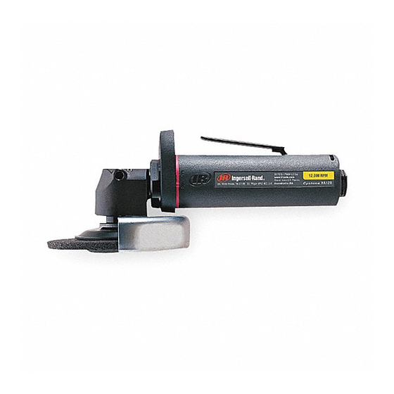
Series HA and HXA Angle Grinders are designed for close–quarter work in the metal fabricating
industry, shipyards, pipe fabrication and limited space applications. They are particularly good
where conduits, pipes, ducts, etc. pass through bulkheads or frames. These small Angle
Grinders are very efficient at grinding weld bead and leaving a fine finish.
Ingersoll–Rand is not responsible for customer modification of tools for applications on which
Ingersoll–Rand was not consulted.
IT IS THE RESPONSIBILITY OF THE EMPLOYER TO PLACE THE INFORMATION
IN THIS MANUAL INTO THE HANDS OF THE OPERATOR.
FAILURE TO OBSERVE THE FOLLOWING WARNINGS COULD RESULT IN INJURY.
PLACING TOOL IN SERVICE
•
Always operate, inspect and maintain this tool in
accordance with American National Standards
Institute Safety Code for Portable Air Tools
(ANSI B186.1).
•
For safety, top performance, and maximum durability
of parts, operate this tool at 90 psig (6.2 bar/620 kPa)
maximum air pressure at the inlet with 3/8" (10 mm)
inside diameter air supply hose.
•
Always turn off the air supply and disconnect the air
supply hose before installing, removing or adjusting
any accessory on this tool, or before performing any
maintenance on this tool.
•
Do not use damaged, frayed or deteriorated air hoses
and fittings.
•
Be sure all hoses and fittings are the correct size and
are tightly secured. See Dwg. TPD905–1 for a typical
piping arrangement.
•
Always use clean, dry air at 90 psig maximum air
pressure. Dust, corrosive fumes and/or excessive
moisture can ruin the motor of an air tool.
•
Do not lubricate tools with flammable or volatile
liquids such as kerosene, diesel or jet fuel.
•
Do not remove any labels. Replace any damaged label.
The use of other than genuine Ingersoll–Rand replacement parts may result in safety hazards, decreased tool performance, and
increased maintenance, and may invalidate all warranties.
Repairs should be made only by authorized trained personnel. Consult your nearest Ingersoll–Rand Authorized Servicenter.
Refer All Communications to the Nearest
Ingersoll–Rand Office or Distributor.
Ingersoll–Rand Company 1999
Printed in U.S.A.
IMPORTANT SAFETY INFORMATION ENCLOSED.
READ THIS MANUAL BEFORE OPERATING TOOL.
03538071
USING THE TOOL
•
Always wear eye protection when operating or
performing maintenance on this tool.
•
Always wear hearing protection when operating this
tool.
•
Keep hands, loose clothing and long hair away from
rotating end of tool.
•
Anticipate and be alert for sudden changes in motion
during start up and operation of any power tool.
•
Keep body stance balanced and firm. Do not
overreach when operating this tool. High reaction
torques can occur at or below the recommended air
pressure.
•
Tool accessories may continue to rotate briefly after
throttle is released.
•
Air powered tools can vibrate in use. Vibration,
repetitive motions or uncomfortable positions may be
harmful to your hands and arms. Stop using any tool
if discomfort, tingling feeling or pain occurs. Seek
medical advice before resuming use.
•
Use accessories recommended by Ingersoll–Rand.
•
This tool is not designed for working in explosive
atmospheres.
•
This tool is not insulated against electric shock.
F
Form P6953
Edition 8
E
September, 1999
P
Advertisement
Table of Contents

Related Manuals for Ingersoll-Rand HA120RG4


Summary of Contents for Ingersoll-Rand HA120RG4
- Page 1 03538071 Form P6953 Edition 8 TPD1685 September, 1999 OPERATION AND MAINTENANCE MANUAL FOR SERIES HA AND HXA ANGLE GRINDERS Series HA and HXA Angle Grinders are designed for close–quarter work in the metal fabricating industry, shipyards, pipe fabrication and limited space applications. They are particularly good where conduits, pipes, ducts, etc.
-
Page 2: Warning Label Identification
WARNING LABEL IDENTIFICATION FAILURE TO OBSERVE THE FOLLOWING WARNINGS COULD RESULT IN INJURY. WARNING WARNING WARNING Always turn off the air sup- Always wear eye protection Always wear hearing ply and disconnect the air when operating or perform- protection when operating supply hose before install- ing maintenance on this this tool. -
Page 3: Placing Tool In Service
GRINDER SPECIFIC WARNINGS • Always match collet size with accessory shank size. operating the Grinder. Pay particular attention to • Always insert tool shank no less than 10 mm in the the fact that allowed speed of a mounted point is collet. - Page 4 “F” on the Housing. To order a front exhaust tool from the factory, substitute the letter “F” for the letter “R” in the above models. Example: HA120RG4 Rear Exhaust Model becomes HA120FG4 Front Exhaust Model. HOW TO ORDER CUSTOM MODELS 1.
- Page 5 NEW GRINDER TO ACCESSORY COLOR MATCHING GUIDE Ingersoll–Rand has pioneered a new color code system accessories for each tool through a matching color designed to: code system on the backing pads and/or other corresponding Grinder accessories. Simplify the identification of rated tool speed via a The chart below demonstrates the color code system unique corresponding color match.
- Page 6 • • Ne jamais lubrifier les outils avec des liquides Utiliser les accessoires recommandés par inflammables ou volatiles tels que le kérosène, le gasol Ingersoll-Rand. • ou le carburant d’aviation. Cet outil n’est pas conçu pour fonctionner dans des •...
- Page 7 SIGNIFICATION DES ETIQUETTES D’AVERTISSEMENT ATTENTION LE NON RESPECT DES AVERTISSEMENTS SUIVANTS PEUT CAUSER DES BLESSURES ATTENTION ATTENTION ATTENTION Couper toujours l’alimentation Porter toujours une Porter toujours des lunettes d’air comprimé et débrancher le protection acoustique de protection pendant flexible d’alimentation avant pendant l’utilisation de cet l’utilisation et l’entretien de d’installer, déposer ou ajuster...
-
Page 8: Mise En Service De L'outil
AVERTISSEMENTS SPECIFIQUES AUX MEULEUSES • Toujours choisir une pince adaptée à la dimension de l’écrou de pince avant de mettre la meuleuse en la queue de l’accessoire. marche. Ne jamais oublier que la vitesse admissible • La queue de l’outil doit toujours être insérée dans la d’une meule sur tige doit être réduite lorsque la pince sur au moins 10 mm. -
Page 9: Spécifications
JAUNE VERT VERT BLEU BLEU GRIS GRIS OCRE OCRE VIOLET (Plan TPD1146–1) SPÉCIFICATIONS 1/4” PINCE Modèle Vitesse d’exploitation maximum HA120RG4 12.000 HA90RG4 9.000 3/8”–24 FILETAGE DE BROCHE HA120RP64 12.000 HA120RP64M 12.000 HXA120RP64 12.000 HA90RP64 9.000 5/8”–11 FILETAGE DE BROCHE HA120RP1045 12.000... - Page 10 MANUAL DE USO Y MANTENIMIENTO PARA AMOLADORAS ANGULARES MODELOS HA Y HXA TPD1685 NOTA Las Amoladoras Angulares Serie HA y HXA están diseñadas para trabajo de cercanía en la industria de fabricación de metales, astilleros, fabricación de tuberías y aplicaciones en espacios reducidos.
-
Page 11: Etiquetas De Aviso
ETIQUETAS DE AVISO AVISO EL HACER CASO OMISO DE LOS AVISOS SIGUIENTES PODRÍA OCASIONAR LESIONES. ADVERTENCIA ADVERTENCIA ADVERTENCIA Cortar siempre el suministro de aire y desconectar la man- Use siempre protección ocular Use siempre protección para guera de suministro de aire cuando utilice esta herramienta los oídos cuando utilice esta antes de instalar, retirar o ajus-... - Page 12 AVISOS ESPECÍFICOS PARA AMOLADORA • Empareje siempre el tamaño de pinza con el tamaño Compruebe el apriete de Tuerca de Pinza antes de de vástago de accesorio. usar la Amoladora. Preste especial atención al hecho • Inserte siempre el vástago de herramienta en la pinza de que la velocidad permitida de un punto de montaje un mínimo de 10 mm.
-
Page 13: Especificaciones
GRIS 15 000 GRIS MARRON 12 000 MARRON VIOLETA 9 000 VIOLETA (Esq. TPD1146–1) ESPECIFICACIONES 1/4” PINZA Modelo Velocidad Libre, rpm HA120RG4 12.000 HA90RG4 9.000 3/8”–24 ROSCA ESTRIADA HA120RP64 12.000 HA120RP64M 12.000 HXA120RP64 12.000 HA90RP64 9.000 5/8”–11 ROSCA ESTRIADA HA120RP1045 12.000... - Page 14 MANUAL DE FUNCIONAMENTO E MANUTENÇÃO PARA TPD1685 SÉRIES DE ESMERILADORAS DE ÂNGULO HA E HXA AVISO As séries de Esmeriladoras de Ângulo HA E HXA são concebidas para trabalho close–quarter na indústria de metais, estaleiros, fabricação de tubos e aplicações espaciais limitadas. Elas são particularmente ideais onde condutas, tubos, canais, etc.
- Page 15 IDENTIFICAÇÃO DO RÓTULO DE ADVERTÊNCIA ADVERTÊNCIA O NÃO CUMPRIMENTO DAS SEGUINTES ADVERTÊNCIAS PODE RESULTAR EM FERIMENTO. ADVERTÊNCIA ADVERTÊNCIA ADVERTÊNCIA Desligue sempre a alimentação de Use sempre óculos de pro- ar e desconecte a mangueira de Use sempre protecção contra tecção quando estiver oper- alimentação de ar antes de insta- o ruído ao operar esta ferra- ando ou executando algum...
- Page 16 ADVERTÊNCIAS ESPECÍFICAS DA ESMERILADORA • Use sempre uma pinça cuja dimensão seja igual ao antes de operar a esmeriladora. Preste particular encabadouro acessório. atenção ao facto de que a velocidade permitida de um • ponto montado é diminuída quando o comprimento do Insira sempre o encabadouro da ferramenta com comprimento que não seja inferior a 10mm no colete.
- Page 17 15,000 CINZA MARRON 12,000 MARRON CLARO 9,000 VIOLETA CLARO VIOLETA (Desenho TPD1146–1) ESPECIFICAÇÕES 1/4” PINÇA Modelo Velocidade Livre rpm HA120RG4 12.000 HA90RG4 9.000 3/8”–24 ROSCA DO FUSO HA120RP64 12.000 HA120RP64M 12.000 HXA120RP64 12.000 HA90RP64 9.000 5/8”–11 ROSCA DO FUSO HA120RP1045 12.000...
- Page 18 (Dwg. TPA1297–6)
- Page 19 PART NUMBER FOR ORDERING PART NUMBER FOR ORDERING Common parts for ALL Front End Plate ....LG2–11 HA and HXA Grinders Front End Plate Spacer .
- Page 20 PART NUMBER FOR ORDERING PART NUMBER FOR ORDERING Nameplate Arbor Bearing Cap ....AG20–531 for standard length 9 000 rpm Additional parts for all HXA models models ending in –EU .
- Page 21 PART NUMBER FOR ORDERING PART NUMBER FOR ORDERING Bevel Gear Nut ..... LA2–578 Wheel Flange Lower Arbor Bearing ....LA2–593 for models ending in P64, Arbor...
- Page 22 PART NUMBER FOR ORDERING PART NUMBER FOR ORDERING 64A Wheel Retaining Screw (for models ending Flange Nut Wrench (L–shaped) in P945M, P945MC, P945ML, P95M, (included with all models using P95MC or P95ML) ....LG2–219M Type 27 Wheels except models 64B Wheel Retaining Screw Washer (for models ending in P945M, P945MC,...
-
Page 23: Maintenance Section
MAINTENANCE SECTION LG2–A48 ERGO HANDLE ASSEMBLY (Dwg. TPD1864) PART NUMBER FOR ORDERING Ergo Handle Assembly ............LG2–A48A Handle Arbor . - Page 24 MAINTENANCE SECTION Always wear eye protection when operating or In the following step, do not allow the Angle Head performing maintenance on this tool. to rotate when separating it from the Motor or Always turn off the air supply and disconnect the air Extension Housing.
- Page 25 MAINTENANCE SECTION 3. Use the Arbor Wrench (65 or 67) to hold the Arbor left–hand thread. Rotate the Housing clockwise to (35 or 55) and using the Flange Nut Wrench (68 remove it. Remove the Arbor Coupling (37), Clamp or 69), unscrew and remove the Flange Nut. Remove Sleeve (38) and Flange Clamp (23).
- Page 26 MAINTENANCE SECTION 3. Remove the Throttle Valve Spring Seat (4), Throttle assembled Throttle Valve, long stem end leading, into Valve Spring (5) and Throttle Valve (6) from the the housing recess. Motor Housing (8). 6. Push the Inlet Screen (2), closed end leading, into the 4.
- Page 27 MAINTENANCE SECTION 7. For HXA models, using snap ring pliers, install the 6. Install the two Rear Spindle Bearing Washers (43) in the Extension Housing in the rear spindle bearing Coupling Retaining Ring (40) on the Spindle Bearing Nut. cavity. 8.
- Page 28 MAINTENANCE SECTION 2. If the Lower Arbor Bearing (34 or 54) is being installed, it is necessary to note the identification 9. Install the motor Clamp Nut (29 or 49), threaded end marks on the Lower Arbor Bearing. One side of the trailing, onto the motor end of the Angle Head.
-
Page 29: Troubleshooting Guide
MAINTENANCE SECTION TROUBLESHOOTING GUIDE Trouble Probable Cause Solution Low power or low free speed Insufficient air pressure Check air line pressure at the Inlet of the tool. It must be 90 psig (6.2 bar/620 kPa). Clogged muffler elements Disassemble the tool and agitate bare Motor Hous- ing and Flange in a clean, suitable, cleaning solu- tion. - Page 30 MAINTENANCE SECTION TROUBLESHOOTING GUIDE Trouble Probable Cause Solution Front Rotor Bearing runs hot Incorrect installation of the Front Reposition the Front Seal Cup Assembly flush Seal Cup Assembly with the face of the Front End Plate Spacer. Front End Plate Spacer rubbing Replace the Front End Plate and Front End Plate the bore of the Front End Plate Spacer combination.
Need help?
Do you have a question about the HA120RG4 and is the answer not in the manual?
Questions and answers