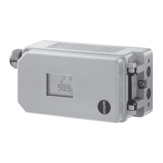
Samson 3730-2 Mounting And Operating Instructions
Electropneumatic positioner
Hide thumbs
Also See for 3730-2:
- Mounting and operating instructions (176 pages) ,
- Quick manual (2 pages) ,
- Operating instructions manual (132 pages)

Related Manuals for Samson 3730-2


Summary of Contents for Samson 3730-2
- Page 1 Series 3730 Type 3730-2 Electropneumatic Positioner Mounting and Operating Instructions EB 8384-2 EN (1300-1611) Firmware version 1.56 Edition April 2016 EB + CD...
- Page 2 Î For the safe and proper use of these instructions, read them carefully and keep them for later reference. Î If you have any questions about these instructions, contact SAMSON‘s After-sales Service Department (aftersalesservice@samson.de). The mounting and operating instructions for the devices are included in the scope of delivery.
-
Page 3: Table Of Contents
Contents Important safety instructions ................8 Article code ....................9 Design and principle of operation ..............10 Additional equipment ...................11 Communication ...................12 Technical data .....................13 Attachment to the control valve – Mounting parts and accessories ....20 Direct attachment ..................22 4.1.1 Type 3277-5 Actuator ..................22 4.1.2 Type 3277 Actuator ..................24 Attachment according to IEC 60534-6 ............26... - Page 4 Contents Operating controls and readings ..............60 Serial interface ....................62 Start-up and settings ...................63 Defining the fail-safe position ................63 Adjusting the volume restriction Q ..............64 Adapting the display direction ..............64 Limiting the signal pressure ................65 Checking the operating range of the positioner ..........65 Initialization ....................66 7.6.1 MAX –...
-
Page 5: Eb 8384-2 En
Contents Valve characteristic selection ..............107 Index ......................126 Note The functions of the EXPERTplus Valve Diagnostics are described in the Operating Instructions EB 8389. EB 8389 is included on the enclosed CD-ROM and is available on our website. EB 8384-2 EN... - Page 6 Firmware revisions 1.01 1.10 The positioner can be configured and operated over the TROVIS-VIEW software after connecting it to the computer over the serial interface and the serial interface adapter. The following status messages have been added: • Code 76 – No emergency mode •...
- Page 7 Firmware revisions 1.42 1.51 All EXPERTplus diagnostic functions are available without having to activate them in the positioner EB 8389 on EXPERTplus Valve Diagnostics). Optional binary input with following actions: • Transmit switching state • Activate local write protection • Switch between automatic and manual modes •...
-
Page 8: Important Safety Instructions
Important safety instructions 1 Important safety instructions For your own safety, follow these instructions concerning the mounting, start-up, and opera- tion of the device: − The device is to be mounted, started up or operated only by trained and experienced personnel familiar with the product. -
Page 9: Article Code
Article code 2 Article code Positioner Type 3730-2 x x x x x x x x 0 x 0 0 x 0 x x With LCD and autotune Explosion protection Without ATEX II 2G Ex ia IIC T6 Gb, II 2D Ex ia IIIC T80°C Db Ex ia IIC T6;... -
Page 10: Design And Principle Of Operation
Design and principle of operation 3 Design and principle of oper- i/p converter with a downstream air capaci- ty booster (7) and the electronics with micro- ation controller (5). The electropneumatic positioner is mounted The positioner is fitted with three binary con- on pneumatic control valves and is used to tacts as standard: A fault alarm output indi- assign the valve position (controlled vari-... -
Page 11: Additional Equipment
<2.4 mA or >21.6 mA. − Direct attachment to SAMSON Type 3277 Actuators Inductive limit switch − Attachment to actuators according to In this version, the rotary shaft of the posi- IEC 60534-6 (NAMUR) -
Page 12: Communication
The positioner changes from the auto- vice module can be downloaded free of matic mode (AUTO) to the manual charge from our website at u www.samson. mode (MAN) or vice versa. de at Services > Software > TROVIS-VIEW. This function is not performed if the posi- Further information on TROVIS-VIEW (e.g. -
Page 13: Technical Data
Design and principle of operation 3.3 Technical data The technical data for the explosion-protected devices may be restricted by the Type 3730-2 Positioner limits specified in the test certificates. Direct attachment to Type 3277 Actuator 3.6 to 30 mm Attachment according to IEC 60534-6 (NAMUR) 3.6 to 300 mm Valve travel Adjustable Attachment according to VDI/VDE 3847... - Page 14 SIL 2 (single device/ solenoid valve HFT = 0) and SIL 3 (redundant configuration/HFT = 1). Explosion protection See Table Summary of explosion protection certificates for Type 3730-2 Positioner Communication (local) SAMSON SSP interface and serial interface adapter Software requirements (SSP)
- Page 15 Design and principle of operation The technical data for the explosion-protected devices may be restricted by the Type 3730-2 Positioner limits specified in the test certificates. Materials Die-cast aluminum EN AC-AlSi12(Fe) (EN AC-44300) acc. to DIN EN 1706 Housing Chromated and powder paint coated · Special version: stainless steel 1.4581 External parts Stainless steel 1.4571 and 1.4301...
- Page 16 Design and principle of operation Options for Type 3730-2 Positioner External position sensor Valve travel Same as positioner 10 m · Flexible and durable · With M12x1 connector · Flame-retardant acc. to Cable VDE 0472 Resistant to oils, lubricants and coolants as well as other aggressive media –60 to +105 °C with a fixed connection between positioner and position sensor...
- Page 17 Design and principle of operation Summary of explosion protection certificates for Type 3730-2 Positioner Type Certification Type of protection/comments Number IECEx PTB 05.0007 Ex ia IIC T4/T5/T6 IP54 and IP65 T80°C Date 2005-02-21 Number 0Ex ia IIC T6X STCC 2Ex s II T6X Valid until 2017-10-01 Number PTB 00 ATEX 2158 II 2G Ex ia IIC T6 Gb...
- Page 18 Design and principle of operation Type Certification Type of protection/comments Class I, Zone 0 AEx ia IIC; Number ID 3012394 Class I, II, III, Div.1, Groups A, B, C, D, E, F, G; Date 2011-08-11 Class I, Div.2, Groups A, B, C, D; Class II, III, Div.2, Groups F, G;...
- Page 19 Design and principle of operation EB 8384-2 EN...
-
Page 20: Attachment To The Control Valve - Mounting Parts And Accessories
The positioner is equipped with the M lever The positioner is suitable for the following (pin position 35) as standard. types of attachment: − Direct attachment to SAMSON Type 3277 Actuator − Attachment to actuators according to IEC 60534-6 (NAMUR) − Attachment according to VDI/VDE 3847 −... - Page 21 Adjustment range at positioner Required [cm²] [mm] Travel [mm] lever position 25.0 120/175/240/350 35.0 355/700/750 10.0 50.0 Attachment according to IEC 60534-6 (NAMUR) SAMSON valves with Type 3271 Adjustment range at positioner Actuator Other control valves Actuator size Rated travel Min. travel Max. travel Required Assigned [cm²] [mm] [mm] [mm]...
-
Page 22: Direct Attachment
Attachment to the control valve – Mounting parts and accessories 4.1 Direct attachment Make sure that the gasket (14) points to- wards the actuator yoke. 4.1.1 Type 3277-5 Actuator 5. 15 mm travel: Keep the follower pin (2) on the M lever (1) on the back of the po- −... - Page 23 Attachment to the control valve – Mounting parts and accessories Lever Symbols Switchover plate (9) 1.1 Nut Actuator stem 1.2 Disk spring extends Follower pin Follower clamp Left attachment Right attachment Screw plug Sealing plug Actuator stem Connecting plate retracts 6.1 Seals Pressure gauge bracket Signal pressure...
-
Page 24: Type 3277 Actuator
Attachment to the control valve – Mounting parts and accessories stalled to allow any condensed water 5. Place positioner on the cover plate in that collects to drain off. such a manner that the follower pin (2) rests on the top of the follower clamp (3). 4.1.2 Type 3277 Actuator Adjust the lever (1) correspondingly and... - Page 25 Attachment to the control valve – Mounting parts and accessories Connection block Lever 1.1 Nut 12.1 Screw 1.2 Disk spring 12.2 Stopper or connection for external piping Follower pin 10 14 Switch plate Follower clamp Gasket Cover plate Formed seal Cover 11 11.1 Gasket...
-
Page 26: Attachment According To Iec 60534-6
Attachment to the control valve – Mounting parts and accessories 4.2 Attachment according to aligned with the NAMUR bracket at mid valve travel). IEC 60534-6 3. Mount connecting plate (6) or pressure − Required mounting parts and accesso- gauge bracket (7) with pressure gauges ries: Table 3 on page 52 on the positioner, making sure the two −... - Page 27 Attachment to the control valve – Mounting parts and accessories Attachment to rod-type yoke Rods with 20 to 35 mm diameter Attachment to NAMUR rib Lever Additional bracket for 1.1 Nut actuators with 1.2 Disk spring 2800 cm² and travel Follower pin ≥...
-
Page 28: Attachment According To Vdi/Vde 3847
Attachment to the control valve – Mounting parts and accessories 4.3 Attachment according to mounting screw is located in the groove of the actuator stem. VDI/VDE 3847 2. Place the adapter bracket (6) on the po- Type 3730-2xxx0xxxx0x0060xx and sitioner and mount using the screws Type 3730-2xxx0xxxx0x0070xx Positioners (6.1). - Page 29 Attachment to the control valve – Mounting parts and accessories 13.1 17.1 17.2 18 18.1 11.1 12.1 Exh. 6.2 6.1 Lever Disk spring Follower pin Follower clamp Blanking plug Adapter block Sealing plug 13.1 Screws Adapter bracket Screws Turnboard Formed seal 17.1 Formed seal 17.2...
- Page 30 Attachment to the control valve – Mounting parts and accessories 7. Insert the screws (13.1) through the mid- Place positioner on the adapter block dle holes of the adapter block (13). (13) in such a manner that the follower pin (2) rests on the top of the follower 8.
- Page 31 Attachment to the control valve – Mounting parts and accessories Attachment to NAMUR rib (see Fig. 8) on the rod and position the formed plate (15) on the opposite side. Use the nuts − Required mounting parts and accesso- and toothed lock washers to fasten the ries: Table 4 on page 52 formed plate onto the studs.
- Page 32 Attachment to the control valve – Mounting parts and accessories 6. Insert the formed seal (17.1) into the For double-acting actuators and actua- turnboard (17) and mount the turnboard tors with air purging, connect the Y2 to the adapter block (13) using the port of the adapter block to the signal screws (17.2).
- Page 33 Attachment to the control valve – Mounting parts and accessories 13.1 17.1 17.2 18.1 Exh. Lever 14.1 1.1 Nut 1.2 Disk spring Follower pin Follower plate 13.1 Screws 3.1 Follower plate 6.2 6.1 Bolt Blanking plug 14.1 Screws Sealing plug Formed plate Adapter bracket Bracket...
-
Page 34: Attachment To Type 3510 Micro-Flow Valve
M8 screws Prior to attaching the positioner to the (11.1) directly into the holes on the yoke. SAMSON Type 3278 Rotary Actuator, 5. Fasten the bracket (10) to the hex bar us- mount the associated adapter (5) to the free ing the hex screw (10.1), washer, and... - Page 35 Attachment to the control valve – Mounting parts and accessories 12.1 11.1 10.1 Lever 1.1 Nut 1.2 Disk spring Follower pin NOTICE Follower plate Only use the connecting plate (6) Connecting plate included in the accessories to connect 6.1 Seals supply and output! Pressure gauge bracket Never screw threaded parts directly...
-
Page 36: Heavy-Duty Version
Attachment to the control valve – Mounting parts and accessories 2. Place coupling wheel (4) with flat side side of the positioner housing (see section facing the actuator on the follower clamp 4.6). (3). Refer to Fig. 11 to align slot so that it 6. - Page 37 Attachment to the control valve – Mounting parts and accessories (7, 8) 10.1 NOTICE 80 mm Only use the connecting plate (6) included in the accessories to connect 130 mm supply and output! Never screw threaded parts directly into housing! Slot Legend for Fig. 10 and Fig. 11...
-
Page 38: Reversing Amplifier For Double-Acting Actuators
4.6 Reversing amplifier for double-acting actuators For the use with double-acting actuators, the positioner must be fitted with a reversing am- plifier, e.g. the SAMSON Type 3710 Revers- ing Amplifier (see Mounting and Operating In- structions EB 8392). If a different reversing amplifier (item no. - Page 39 Coupling wheel Adapter housing Screw 10.1 Screws Disk spring Spacer Adhesive label Actuator shaft or adapter Adapter 10.1 10.1 Attachment according to VDI/VDE 3845 SAMSON Type 3278 (Sept. 2010) fixing level 1, AA1 to AA4 VETEC S160, VETEC R size, see section 15.1 Fig. 13: Attachment to rotary actuators (heavy-duty version) EB 8384-2 EN...
-
Page 40: Reversing Amplifier (1079-1118 Or 1079-1119)
Attachment to the control valve – Mounting parts and accessories The following applies to all reversing am- 2. Thread the special nuts (1.3) from the ac- plifiers: cessories of the reversing amplifier into the boreholes of the connecting plate. The signal pressure of the positioner is sup- plied at the output 1 of the reversing amplifi- 3. - Page 41 Attachment to the control valve – Mounting parts and accessories From the positioner Output 38 Supply 9 Control signals to the actuator Reversing amplifier Connecting plate 1.1 Special screws 6.1 O-rings 1.2 Gasket 6.2 Screws 1.3 Special nuts 1.4 Rubber seal 1.5 Sealing plug 1.6 Filter Fig. 14: Mounting a reversing amplifier (1079-1118 or 1079-1119)
-
Page 42: Attachment Of External Position Sensor
Attachment to the control valve – Mounting parts and accessories 4.7 Attachment of external po- Note sition sensor − In addition, the instructions in sections 5.1 and 5.2 apply for the pneumatic and elec- trical connection. Operation and setting are described in sections 7 and 8. -
Page 43: Mounting The Position Sensor With Direct Attachment
Attachment to the control valve – Mounting parts and accessories 4.7.1 Mounting the position − Turn the connecting plate (9) so that the correct symbol for the fail-safe action sensor with direct at- "actuator stem extends" or "actuator stem tachment retracts"... - Page 44 Attachment to the control valve – Mounting parts and accessories Type 3277 Actuator with 175 to 750 cm²: 6. Place the mounting plate together with the sensor onto the actuator yoke so that The signal pressure is routed to the connec- the follower pin (2) rests on the top of the tion at the side of the actuator yoke for the follower clamp (3).
-
Page 45: Mounting The Position Sensor With Attachment According To Iec 60534-6
Attachment to the control valve – Mounting parts and accessories 4.7.2 Mounting the position 120 to 350 cm² actuators with 15 mm rated travel. For other actuator sizes or travels, se- sensor with attachment lect the lever and pin position from the travel according to table on page 21. -
Page 46: Mounting The Position Sensor To Type 3510 Micro-Flow Valve
Attachment to the control valve – Mounting parts and accessories 4.7.3 Mounting the position hole for pin position 17. Place the lever (1) and disk spring (1.2) on the sensor sensor to Type 3510 Mi- shaft. Place the lever in mid-position and cro-flow Valve hold it in place. Screw on the nut (1.1). −... -
Page 47: Mounting On Rotary Actuators
Attachment to the control valve – Mounting parts and accessories 4.7.4 Mounting on rotary ac- 4. Place the lever (1) and disk spring (1.2) on the sensor shaft. Place the lever in tuators mid-position and hold it in place. Screw −... -
Page 48: Mounting The Leakage Sensor
Attachment to the control valve – Mounting parts and accessories 4.8 Mounting the leakage The M8 threaded connection on the NAMUR rib should preferably be used to mount the sensor sensor (Fig. 19). Fig. 19 Normally, the control valve is delivered with If the positioner was mounted directly onto positioner and leakage sensor already the actuator (integral attachment), the... -
Page 49: Attaching Positioners With Stainless Steel Housings
Attachment to the control valve – Mounting parts and accessories 4.9 Attaching positioners with Attachment to rotary actuators stainless steel housings All mounting kits from Table 5 can be used except for the heavy-duty version. Connect- Positioners with stainless steel housings re- ing plate in stainless steel. -
Page 50: Required Mounting Parts And Accessories
Attachment to the control valve – Mounting parts and accessories Attachment according to IEC 60534-6 Should other valve accessories be used (NAMUR rib or attachment to rod-type which vent the actuator (e.g. solenoid valve, yokes) and to rotary actuators volume booster, quick exhaust valve), this ex- haust air must also be included in the purg- The positioner requires an additional port for ing function. - Page 51 Attachment to the control valve – Mounting parts and accessories Table 2: Direct attachment to Type 3277 Actuator (Fig. 4) Order no. Standard version for actuators 175, 240, 350, 355, 700, 750 cm² 1400-7453 Mounting parts Version compatible with paint for actuators 175, 240, 350, 355, 700, 750 cm² 1402-0941 G ...
- Page 52 Table 4: Attachment according to VDI/VDE 3847 (Fig. 6 and Fig. 8) Electropneumatic positioners with VDI/VDE 3847 interface (Type 3730-2xxx0xxxx0x0070xx) Order no. Interface adapter 1402-0257 Mounting kit for attachment to SAMSON Type 3277 Actuator with 175 to 750 cm² 1402-0868 Mounting kit for attachment to SAMSON Type 3271 Actuator or non-SAMSON 1402-0869 actuators ISO 228/1-G¼...
- Page 53 1400-9837 Attachment to SAMSON Type 3278 with 160/320 cm², CrNiMo steel bracket 1400-7614 Attachment to SAMSON Type 3278 with 160 cm² and to VETEC Type S160, Type R and 1400-9245 Type M, heavy-duty version 1400-5891 Attachment to SAMSON Type 3278 with 320 cm² and to VETEC Type S320, heavy-duty...
- Page 54 Table 6: General accessories Order no. Serial interface adapter (SAMSON SSP interface to RS-232 port on a computer) 1400-7700 Isolated USB interface adapter (SAMSON SSP interface to USB port on a computer) 1400-9740 including TROVIS-VIEW CD-ROM Table 7: Attachment of external position sensor Order no.
-
Page 55: Connections
Connections 5 Connections NOTICE Risk of malfunction due to failure to comply WARNING with required air quality. Risk of injury due to the actuator stem ex- Only use supply air that is dry and free of oil tending or retracting. and dust. -
Page 56: Signal Pressure (Output)
Connections 5.2 Electrical connections Actuator stem extends FA (AIR TO OPEN) Fail-close (for globe and angle valves): Required supply pressure = Upper bench DANGER range value + 0.2 bar, at least 1.4 bar. Risk of electric shock and/or the formation of an explosive atmosphere. Actuator stem retracts FE (AIR TO CLOSE) For electrical installation, observe the rele- Fail-open (for globe and angle valves):... - Page 57 Connections Clause 12.2.2.7 applies when running multi- There is a second M20 x 1.5 threaded hole core cables and wires with more than one in the housing that can be used for addition- intrinsically safe circuit. al connection, when required. The screw ter- minals are designed for wire cross-sections The radial thickness of the insulation of a of 0.2 to 2.5 mm².
- Page 58 Connections Adapter M20 x 1.5 to ½ NPT Order no. NOTICE Powder-coated aluminum 0310-2149 Malfunction due the current falling below Stainless steel 1400-7114 minimum current. Do not allow the set point to fall below 3.8 mA. Note In positioners for attachment according to Accessories VDI/VDE 3847, the terminal designation of the limit switches 41/42 and 51/52 as well Cable glands M20 x 1.5 Order no.
-
Page 59: Switching Amplifier
Connections 5.2.1 Switching amplifier For operation of the limit switches, switching amplifiers must be connected in the output circuit. To ensure the operating reliability of the positioner, the amplifiers should comply with the limit values of the output circuits conforming to EN 60947-5-6. Observe the relevant regulations for installa- tion in hazardous areas. -
Page 60: Operating Controls And Readings
Operating controls and readings 6 Operating controls and Volume restriction Q readings The volume restriction serves to adapt the air output capacity to the size of the actuator. Rotary pushbutton Depending on the air passage at the actua- The rotary pushbutton is located underneath tor, two fixed settings are available. - Page 61 Operating controls and readings Manual mode Closed-loop operation Code Malfunction/fault Bar graph for set point deviation or lever Designation position Position Parameters Units Limit switch Limit switch alarm 1 alarm 2 Enable Fail-safe position active Maintenance demanded configuration Maintenance required Blinking icon: out of specification Automatic Initialization in progress...
-
Page 62: Serial Interface
The operator software is TROVIS-VIEW with cates the lever position in degrees in relation installed device module 3730-2. to the mid-axis. One bar element corre- sponds to approximately a 5° angle of rota- tion. -
Page 63: Start-Up And Settings
Start-up and settings 7 Start-up and settings Note The positioner performs a test in the start-up NOTICE phase while following its automation task at Risk of malfunction due to incorrect sequence the same time. of mounting, installation, and start-up. During the start-up phase, operation on site Keep the following sequence. -
Page 64: Adjusting The Volume Restriction Q
The position of volume restriction Q also de- connections pends on how the signal pressure is routed at the actuator in SAMSON actuators: − The SIDE position applies for actuators Reading direction for left with a signal pressure connection at the attachment of pneumatic side, e.g. -
Page 65: Limiting The Signal Pressure
Start-up and settings If the displayed data appear upside down, Limit the signal pressure: proceed as follows: Turn Code 2 Pressure limit Press , Code 2 blinks. Default: No Turn Required reading direction Press to confirm reading direction. Turn Code 16 7.4 Limiting the signal pressure Press , Code 16 blinks. -
Page 66: Initialization
Start-up and settings Check the operating range: WARNING Risk of injury due to the actuator stem ex- Manual set point w tending or retracting. (current angle of rotation is Before exchanging the lever or changing the indicated) pin position, disconnect the supply air and electrical auxiliary power. - Page 67 Start-up and settings − Maximum range (MAX) (standard range) Initialization mode for simple start-up of Initialization successfully valves with two clearly defined mechani- completed. Positioner in automatic mode ( ) cal end positions, e.g. three-way valves (see section 7.6.1) − Nominal range (NOM) The time required for the initialization proce- Initialization mode for all globe valves dure depends on the actuator transit time and...
-
Page 68: Max - Initialization Based On Maximum Range
Start-up and settings Enable configuration: Set point Fail-safe Direction of Valve position action CLOSED Note OPEN at If no settings are entered within 120 sec- Actuator stem onds, the enabled configuration function be- extends (FA) 0 % 100 % comes invalid. AIR TO OPEN Actuator stem retracts (FE) 100 %... -
Page 69: Nom - Initialization Based On Nominal Range
Start-up and settings travel/angle range end (Code 9) can also cally canceled (error message Code 52) be- only be displayed and modified in %. cause the nominal travel could not be achieved. For a reading in mm/°, enter the pin posi- tion (Code 4). -
Page 70: Man - Initialization Based On A Manually Selected Range
Start-up and settings Press with limits of lower travel/angle range value (Code 8) and upper travel/angle range val- Turn Code 5 ue (Code 9). Press , Code 5 blinks. Enable configuration: Turn Nominal travel of the valve Press Note Select the initialization mode: If no settings are entered within 120 sec- onds, the enabled configuration function be- comes invalid. -
Page 71: Sub - Substitute Calibration
Start-up and settings 7.6.4 SUb – Substitute calibra- Select the initialization mode: tion Init mode A complete initialization procedure takes Default MAX several minutes and requires the valve to move through its entire travel range several times. In the SUb initialization mode, the Turn ... - Page 72 Start-up and settings Select the initialization mode: Enable configuration Default: No Init mode Default MAX Turn g Code 3, display: No Press , Code 3 blinks. Turn Code 6 Turn YES Press Press , display: Turn SUb Press to confirm the SUb as the initializa- Enter the pin position and nominal range: tion mode.
- Page 73 Start-up and settings Change pressure limit and control parame- Enter closing direction and blocking position: ters: Closing direction (direction of rotation causing the valve to Note move to the CLOSED position (view onto positioner display) Do not change the pressure limit (Code 16). Default: CCL (counterclockwise) Only change the control parameters K (Code 17) and T (Code 18) if the settings of...
-
Page 74: Zero Calibration
Start-up and settings Zero point calibration Note Finally, if process operations allow it, the ze- Since initialization has not been completed, ro point must be calibrated according to sec- the error code 76 (no emergency mode) and tion 7.7. possibly also error code 57 (control loop) may appear on the display. -
Page 75: Reset To Default Settings
Start-up and settings Perform zero calibration: Turn g Code 36, display: ••–••– Press , Code 36 blinks. Turn Std Init mode Default MAX Press All start-up parameters as well as the diag- nosis are reset to their default values. Turn Code 6 Press , Code 6 blinks. -
Page 76: Operation
Operation 8 Operation Turn to select the required code. Press to activate the selected code. The code number starts to blink. WARNING Risk of injury due to the actuator stem ex- Turn to select the setting. tending or retracting. Press to confirm the selected setting. -
Page 77: Fail-Safe Position (Safe)
Operation Note The positioner automatically returns to Automatic mode Code 0 if no settings are made within 120 seconds, but remains in the manual mode. Switching to manual mode (MAN) Switch to automatic mode Turn Code 0 Press , Code 0 blinks. Turn ... -
Page 78: Fault/Malfunction
Operation been determined. The wear tolerance will Press , Code 0 blinks. soon be exhausted or is reducing at a Turn and select the required operating faster rate than expected. Maintenance is mode (AUtO or MAN). necessary in the medium term. Press −... -
Page 79: Confirming Error Messages
Operation If fault alarms exist, the possible source of Confirming error message: error is displayed in Code 49 onwards. In Turn Select the error code that you this case, Err is displayed. want to confirm. Press The error message is confirmed. Example: Error caused by pin position Refer to the code list (section 14) for possible... -
Page 80: Adjusting The Limit Switch
Adjusting the limit switch 9 Adjusting the limit switch ever, can also be adjusted to indicate inter- mediate valve positions. The positioner version with an inductive limit The required switching function, i.e. whether switch has an adjustable tag (1) mounted on the output relay is to be picked up or re- the axis of rotation, which operates the prox- leased when the tag enters the field, must be... -
Page 81: Retrofitting An Inductive Limit Switch
Adjusting the limit switch Software adaptation For OPEN position: − Code 38 (inductive alarm is set to YES). Initialize the positioner. − The inductive limit switch is connected to Move the valve to 95 % in the MAN the terminals +41/–42. mode (see display). −... - Page 82 Adjusting the limit switch 1. Take off the rotary pushbutton (3) and cap (1), unthread the five fastening screws (2) and lift off the plastic cover (9) together with the display, taking care not to dam- age the ribbon cable (between PCB and display).
-
Page 83: Maintenance
11 Servicing explosion-protected When updates are performed by a service employee appointed by SAMSON, the up- devices date is confirmed on the device by the test If a part of the device on which the explosion mark assigned by SAMSON’s Quality Assur-... -
Page 84: Maintenance, Calibration And Work On Equipment
Maintenance, calibration and work on equipment Updates on site: Updates on site are only permitted after the plant operator presented a signed hot work permit. After updating has been completed, add the current firmware to the nameplate; this can be done using labels. 13 Maintenance, calibration and work on equipment Interconnection with intrinsically safe cir-... -
Page 85: Code List
Code list 14 Code list Code Parameter – Readings/ Description values [default setting] Note: Codes with marked with an asterisk (*) must be enabled with Code 3 prior to configuration. Operating mode Switchover from automatic to manual mode is bumpless. In fail-safe position, the S icon is displayed. [MAN] Manual mode In MAN and AUtO mode, the system deviation is represented by the AUtO Automatic mode bar graph elements. - Page 86 Code list Code Parameter – Readings/ Description values [default setting] Nominal range Nominal valve travel or opening angle must be entered for nominal (NOM) or substitute (SUb) initialization. mm or angle °, ESC The possible adjustment range depends on the pin position from the table for Code 4.
- Page 87 Code list Code Parameter – Readings/ Description values [default setting] Travel/angle range end Upper range value for travel/angle in nominal or operating range (upper x-range value) The value is displayed or must be entered. 20.0 to [100.0 %] of the The characteristic is adapted. nominal range, ESC Example: The operating range is modified, for example, to limit the Note: Specified in mm or...
- Page 88 Code list Code Parameter – Readings/ Description values [default setting] 13* w-end The upper range value of the set point range must be greater than lower range value (w-start). 25.0 to [100.0 %] of the set point range, ESC 100.0 % = 20 mA 14* Set point cutoff decrease If the set point w reaches up to the entered percentage at the final value that causes the valve to close, the actuator is immediately com-...
- Page 89 Linear [0] to 9, ESC Equal percentage Reverse equal percentage SAMSON butterfly valve, linear SAMSON butterfly valve, equal percentage VETEC rotary plug valve, linear VETEC rotary plug valve, equal percentage Segmented ball valve, linear Segmented ball valve, equal percentage User-defined (defined over operator software) Note The various characteristics are listed in the Appendix (section 16).
- Page 90 Code list Code Parameter – Readings/ Description values [default setting] 23* Total valve travel Totaled full valve travel cycle Can be reset to 0 in Code 36 – Std. [0] to 99 · 10 , RES, ESC Note Exponential reading from 9999 travel cycles on- The total valve travel is saved in a non-volatile memory after every wards...
- Page 91 Code list Code Parameter – Readings/ Description values [default setting] 26* Limit A1 Alarm A1 responds when the value falls below the limit. Software limit value A1 is displayed or can be changed in relation to 0.0 to 100.0 %, [2.0 %] of the operating range.
- Page 92 Code list Code Parameter – Readings/ Description values [default setting] 31* Position transmitter test Testing the position transmitter. Values can be entered in relation to the operating range. –10.0 to 110.0 % of the operating range, [default The momentary valve position is used in initialized positioners locally value is last indicated val- as the start value (bumpless changeover to the test mode).
- Page 93 Code list Code Parameter – Readings/ Description values [default setting] 36* Reset Std: Resets all parameters and diagnosis data to their default set- tings. After a reset, the positioner must be re-initialized. [No], Std, diAG, ESC diAG: Resets diagnosis data only. Plotted reference graphs and logs remain saved.
- Page 94 Code list Code Parameter – Readings/ Description values [default setting] 45 Solenoid valve info Read only YES, HIGH/LOW, No Indicates whether a solenoid valve is installed or not. If a voltage supply is connected at the terminals of the installed sole- noid valve, YES and HIGH appear on the display in alternating se- quence.
- Page 95 Code list Error codes – Condensed state message active, when prompted, Err appears. Recommended action When fault alarms exist, they are displayed here. 51 Δx < permissible Insufficient measuring span of the lever. range • Pin not mounted properly • Wrong lever An angle of rotation smaller than 16°...
- Page 96 Code list Error codes – Condensed state message active, when prompted, Err appears. Recommended action When fault alarms exist, they are displayed here. 54 Initialization – A solenoid valve is installed (Code 45 = YES) and has not been connected solenoid valve or not properly.
- Page 97 Code list Error codes – Condensed state message active, when prompted, Err appears. Recommended action When fault alarms exist, they are displayed here. 58 Zero point Zero point incorrect Error can occur when the positioner's attachment position is shifted or when the valve trim is worn, particularly with soft-sealed plugs.
- Page 98 If necessary, adjust the current source's lower limit so that no values lower than 4 mA can be applied. 64 i/p converter (y) Current circuit of i/p converter interrupted. Status classification Maintenance alarm (cannot be classified) Recommended Cannot be remedied. Return positioner to SAMSON AG for repair. action EB 8384-2 EN...
- Page 99 Additional indication at the fault alarm contact Status classification [Maintenance alarm] Recommended action Confirm error. If this is not possible, return positioner to SAMSON AG for repair. Data errors Error codes – Recommended Condensed state message active, when prompted, Err appears.
- Page 100 Additional indication at the fault alarm contact Status classification [Maintenance required] Recommended action Return positioner to SAMSON AG for repair. General parameters Error in parameters not critical to control operation. Status classification [Maintenance required] Recommended action Confirm error. Check and, if necessary, change the settings of the re- quire parameters.
- Page 101 Maintenance alarm (cannot be classified) Status classification Interrupt current signal and restart the positioner. Recommended action If not successful, return positioner to SAMSON AG for repair. Error in option parameters. Option parameters [Maintenance required] Status classification Recommended action Return positioner to SAMSON AG for repair.
- Page 102 Code list Diagnosis errors Error codes – Recommended Condensed state message active, when prompted, Err appears. action When fault alarms exist, they are displayed here. Diagnostic messages Messages generated by the extended diagnostics Status classification Maintenance required (cannot be classified) Diagnostic Error in parameters not critical to control operation.
-
Page 103: Dimensions In Mm
Dimensions in mm 15 Dimensions in mm Pressure Attachment according to IEC 60534-6 gauge or connecting plate External position bracket sensor Lever (see Fig. 29) Direct attachment M20x1.5 Output (38) Supply (9) Fig. 26: NAMUR and direct attachment EB 8384-2 EN... - Page 104 Dimensions in mm Attachment according to VDI/VDE 3847 to Type 3277 Lever (see Fig. 29) Attachment according to VDI/VDE 3847 to a NAMUR Fig. 27: Attachment according to VDI/VDE 3847 EB 8384-2 EN...
- Page 105 Dimensions in mm Heavy-duty version Output Y Output Y Supply (9) Reversing Output Y Output Y amplifier (optional)* Ø 101 Light version Output A1 Supply (9) Reversing amplifier Output A2 (optional)* Connecting plate G ¼ or ¼ NPT * Reversing amplifier Type 3710 (see drawing of heavy-duty version for dimensions) −...
-
Page 106: Fixing Levels According To Vdi/Vde 3845 (September 2010)
Dimensions in mm Lever 10...17 17 mm 25 mm 33 mm 25 mm 50 mm 66 mm 70 mm 100 mm 116 mm 100 mm 200 mm 216 mm Fig. 29: Lever 15.1 Fixing levels according to VDI/VDE 3845 (September 2010) Fixing level 2 (bracket surface) Fixing level 1 (actuator surface) Actuator Dimensions in mm Size Ød 5.5 for M5 5.5 for M5 5.5 for M5 ØD 5.5 for M5... -
Page 107: Valve Characteristic Selection
Valve characteristic selection 16 Valve characteristic selection The characteristics that can be selected in Code 20 are shown in the following in graph form. Note A characteristic can only be defined (user-defined characteristic) using a workstation/operat- ing software (e.g. TROVIS-VIEW). Linear (select characteristic: 0) Travel/ angle of rotation [%] Reference variable [%]... - Page 108 SAMSON butterfly valve linear (select SAMSON butterfly valve equal percentage characteristic: 3) (select characteristic: 4) Travel/ angle of rotation [%] Travel/ angle of rotation [%] Reference variable [%] Reference variable [%] VETEC rotary plug valve linear (select VETEC rotary plug valve equal percentage characteristic: 5) (select characteristic: 6)
- Page 109 EB 8384-2 EN...
- Page 110 EB 8384-2 EN...
- Page 111 EB 8384-2 EN...
- Page 112 EB 8384-2 EN...
- Page 113 EB 8384-2 EN...
- Page 114 EB 8384-2 EN...
- Page 115 EB 8384-2 EN...
- Page 116 EB 8384-2 EN...
- Page 117 EB 8384-2 EN...
- Page 118 EB 8384-2 EN...
- Page 119 EB 8384-2 EN...
- Page 120 EB 8384-2 EN...
- Page 121 EB 8384-2 EN...
- Page 122 EB 8384-2 EN...
- Page 123 EB 8384-2 EN...
- Page 124 EB 8384-2 EN...
- Page 125 EB 8384-2 EN...
-
Page 126: Index
Index Index Configuration At the positioner ......76 Connections Accessories ........50–52 Electric ........... 56 Additional equipment Pneumatic ........55 External position sensor ....12 Controlled variable ....... 10 Leakage sensor ....... 12 Limit switch ........11 Solenoid valve ........ 11 Default settings ........ - Page 127 Index Nominal range (NOM) ..... 67, 69 Substitute calibration (SUb) ..67, 71 Select characteristic ....89, 107–108 Serial interface ....... 12, 83 Leakage sensor ........12 Set point ..........10 Attachment ........48 Signal pressure Limit switch Limit..........65 Electrical connection ......
- Page 128 SAMSON AG · MESS- UND REGELTECHNIK Weismüllerstraße 3 · 60314 Frankfurt am Main, Germany Phone: +49 69 4009-0 · Fax: +49 69 4009-1507 EB 8384-2 EN samson@samson.de · www.samson.de...
Need help?
Do you have a question about the 3730-2 and is the answer not in the manual?
Questions and answers