
Subscribe to Our Youtube Channel
Related Manuals for ETAS ES595.1


Summary of Contents for ETAS ES595.1
- Page 1 ES595.1 Interface Module (1xETK, 2xCAN, 2xLIN, 2xFlexRay, 1xEthernet) User‘s Guide...
- Page 2 The data in this document may not be altered or amended without special noti- fication from ETAS GmbH. ETAS GmbH undertakes no further obligation in rela- tion to this document. The software described in it can only be used if the customer is in possession of a general license agreement or single license.
-
Page 3: Table Of Contents
Power-Saving Feature ........22 ES595.1 - User’s Guide... - Page 4 Configuring the ES595.1 ........
- Page 5 ES595.1 ........
- Page 6 10 ETAS Contact Addresses ........
-
Page 7: About This Manual
The presentation looks as follows: Goal definition: any advance information... • Step 1 Any explanation for step 1... • Step 2 Any explanation for step 2... • Step 3 Any explanation for step 3... ES595.1 - User’s Guide... -
Page 8: Scope Of Supply
(see chapter 9.1 on page 77). Additional cables and adapters can be obtained separately from ETAS. A list of available accessories and their order designation is located in chapter "Cable and Accessoires"... -
Page 9: Basic Safety Notices
• "Requirements for Users and Duties for Operators" on page 9, • "Intended Use" on page 9. General Safety Information Please observe the Product Safety Notices ("ETAS Safety Notice") and the follow- ing safety notices to avoid health issues or damage to the device. Note Carefully read the documentation (Product Safety Advice and this User's Guide) that belongs to the product prior to the startup. - Page 10 The connection to power outlets is not allowed! To prevent an inadvertent insertion in power outlets, ETAS recom- mends to equip the power cables with safety banana plugs in areas with power outlets. ES595.1 - User’s Guide...
- Page 11 • Use exclusively ETAS cables at the connections of the module! • Adhere to the maximum permissible cable lengths! • Do not use any damaged cables! Cables may be repaired only by ETAS! • Never apply force to insert a plug into a socket. Ensure that there is no contamination in and on the connection, that the plug fits the socket, and that you correctly aligned the plugs with the connection.
- Page 12 ETAS Maintenance The product is maintenance-free. Repair If an ETAS hardware product should require a repair, return the product to ETAS. Cleaning the module housing • Use a dry or lightly moistened, soft, lint-free cloth for cleaning the module housing.
-
Page 13: Hardware Description
– even in sizeable module networks. The ES595.1 module and the relevant cables are intended for use in the lab, on the test bench and in the passenger cell of vehicles. Features Overview of the major features of the ES595.1:... -
Page 14: Housing
The housings of this device family can also quickly and easily be connected to one another (see the chapter 5.1 on page 29). The ES595.1 is intended for use in the lab, on the test bench and in the passen- ger cell of vehicles. -
Page 15: Interfaces
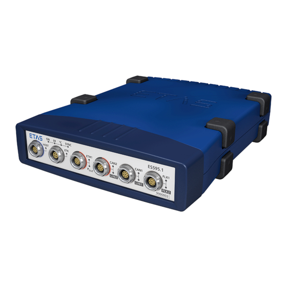
ON ER °C S YNC HOST ETH1 CAN2 CAN1 FLX1 LIN2 LIN1 FLX2 Fig. 3-2 Front Panel 3.4.2 Back Panel The interface 7-29V (power supply) is on the back panel of the ES595.1. 7‐29V Fig. 3-3 Back Panel ES595.1 - User’s Guide... -
Page 16: Leds
Flash Codes 3.5.2 Operational State of the Module Four LEDs can be found top left on the front panel of the ES595.1(see Fig. 3-2 on page 15). They indicate operational, error and synchronization states. • ON: power supply and operational state •... -
Page 17: Functional State Of Individual Interfaces
LEDs assigned to the interfaces of the module can be found on the front panel of the device (see Fig. 3-2 on page 15). If the ES595.1 is powered on (operational state "On") they indicate the following functional states at the assigned inter-... - Page 18 An LED CAN1 is assigned to the interface CAN1 and an LED LIN1 is assigned to the interface LIN1. Display Functional State CAN1 Yellow, flashing Communication at the interface CAN1 Communication interrupted LIN1 Yellow, flashing Communication at the interface LIN1 Communication interrupted ES595.1 - User’s Guide...
- Page 19 Yellow, flashing Yellow, flashing FlexRay node active (channel A and chan- nel B), waiting for synchroniziation Yellow Yellow FlexRay node active (channel A and chan- nel B), synchronized, ready to exchange data ES595.1 - User’s Guide...
- Page 20 Hardware Description ETAS ES595.1 - User’s Guide...
-
Page 21: Functional Description
8/100 MBit/s Fig. 4-1 Block Diagram To fulfill the operation demands in the vehicle, the interfaces of the ES595.1 are each routed to an Lemo socket. Power Supply (7-29V DC) The power supply interface (7-29V DC) is routed to a 2-pin connector (Lemo socket) on the back panel of the module. -
Page 22: Host Port (Host)
Energy consumption must be as low as possible when used in the vehicle because the measuring equipment is powered by a battery. This is why the ES595.1 module at the Ethernet interfaces is equipped with a link signal detector for an automatic power-saving feature. -
Page 23: Module Network
4.6.1 Initialization If an ETK type supported by the ES595.1 is connected to the ETK interface it is recognized automatically. The ETK interface is automatically initialized. If an ETK type which is not supported by the ES595.1 is connected to the ETK interface the overall system behaves, as if no ETK is connected. -
Page 24: Operating Modes
• possibility to configure the number of variables per measure rate. CAN Interface (CAN1/LIN1, CAN2/LIN2) The ES595.1 has two CAN interfaces. One each of the CAN interfaces is routed to the two 8-pin CAN1/LIN1 and CAN2/LIN2 connectors (Lemo socket) on the front panel. -
Page 25: Operating Modes
4.7.1 Operating Modes The CAN interfaces of the ES595.1 can be operated in High-Speed CAN link (ISO 11898-2) or Low-Speed CAN link (ISO 11898-3). Switching between the two operating modes is controlled by software. The operating mode can be selected individually for each interface. -
Page 26: Lin Interface (Can1/Lin1, Can2/Lin2)
51. 4.8.3 Power Supply on the Bus The LIN nodes of the ES595.1 can either be powered externally by the LIN bus or internally by the module. The type of power supply must be configured in the application software. -
Page 27: Flexray Interface (Flx1, Flx2)
If there is no access or no possibility to use the LIN_UBATT voltage as reference and supply voltage, the LIN transceivers of the LIN node of the ES595.1 must be powered by a connectable internal power source of the module . -
Page 28: Firmware Update
4.10 Firmware Update The firmware of the ES595.1 can be updated by the user so that future versions of the module can also be implemented. The firmware is updated on the con- nected PC using service software "Hardware Service Pack" (HSP). -
Page 29: Getting Started
5.1.2 Fixing a Module onto a Carrier System The ES595.1 has a rugged metal housing with nonskid plastic feet. The unit can easily be screwed onto a carrier system for installation in a vehicle or in the lab. The screw thread for attaching your device is already contained in the housing and is easily accessible. -
Page 30: Connecting Several Modules Mechanically
5.1.3 Connecting Several Modules Mechanically As ETAS system housing was used, the ES595.1 can also be connected to mod- ules of the ETAS compact line (ES59x, ES6xx, ES910). These can be combined easily using the T-Brackets provided to form larger blocks. -
Page 31: Fig. 5-3 Connecting The Es595.1 To Another Module
ETAS Getting Started Fig. 5-3 Connecting the ES595.1 to Another Module • Quarter-turn the seals of the T-Brackets. This locks the connection of the two modules. • Click the other two T-Brackets into the assembly slits on the opposite long side of the device and lock these brackets too. -
Page 32: Applications
Getting Started ETAS Applications For applications, the ES595.1 has direct access to XETK ECUs and to ECUs and vehicle buses. Note You can find a list of applications supported by the ES595.1 in chapter 7.6.2 on page 51. ES592 7 ... 29 V DC ES595 7 ... -
Page 33: Wiring
5.3.1 “HOST” Port To connect the ES595.1 module with the PC (“HOST” port), you require the CBE100 cable provided. To connect the ES595.1 with the PC • Connect the HOST port of the ES595.1 with the PC interface cable CBE100. -
Page 34: Eth1" Port
Getting Started ETAS 5.3.3 “ETH1” Port To connect the ES595.1 module with other modules (“ETH1” port), you require the CBE130 cable. Simple Module Network A simple module network consists of a single ES595.1 module with connected network or measure modules. ES59x measure modules are used in the following example. - Page 35 ETH1 port of the superordinate ES595.1 module The superordinate ES59x module is nearer the host PC in the hierarchy. • Connect further ES59x modules in accordance with this principle with other ETH ports of the ES59x module. ES595.1 - User’s Guide...
-
Page 36: Configuring The Es595.1
Getting Started ETAS Configuring the ES595.1 The ES595.1 is configured at the PC via a graphic user interface. A web browser application is used as an interface. 5.4.1 Web Interface The web interface of the ES595.1 consists of a home page, a page for custom- ized configuration of the interfaces for the "Wake Up"... -
Page 37: Troubleshooting Problems
Please observe the LED which provides information on the functions of the inter- face and the ES595.1 (see the chapter "LEDs" on page 16) to be able to judge the operational state of the ES595.1 as well as troubleshooting measures. - Page 38 PCMCIA network your laptop? card in your laptop. PCM- CIA cards with an 8- or 16-bit data bus are not suitable. Only use PCM- CIA cards with a 32-bit data bus, mini-PCI or ExpressCards. ES595.1 - User’s Guide...
-
Page 39: Problems And Solutions
Windows XP and Vista systems. Network security policies, however, may request the APIPA mechanism to be disabled. In this case, you cannot use a network adapter which is configured for DHCP to access ETAS hardware. The ETAS Net- work Manager displays a warning message. -
Page 40: Search For Ethernet Hardware Fails
If you use more than one PC or notebook for accessing the same ETAS hardware, the network adapters used must be configured to use the same logical network. If this is not possible, it is necessary to switch the ETAS hardware off and on again between different sessions (repowering). -
Page 41: Personal Firewall Blocks Communication
Ethernet hardware at all, although the configuration parameters are correct. Certain actions in ETAS products may lead to some trouble if the firewall is not properly parameterized, e.g. upon opening an experiment in ASCET or searching for hardware from within INCA or HSP. - Page 42 • Directed IP broadcasts via UDP to the network configured for the ETAS application, destination port 18001 • Outgoing IP unicasts via UDP to any IP in network configured for the ETAS application, destination ports 69, 18001, 18017 or 49152 to 50175 •...
- Page 43 To unblock a product: • In the "Windows Security Alert" dialog window, click on Unblock. The firewall no longer blocks the ETAS product in question (in the example: ASCET). This decision sur- vives a restart of the program, or even the PC.
- Page 44 This tab lists the exceptions not blocked by the fire- wall. Use Add Program or Edit to add new pro- grams, or edit existing ones. • Make sure that the ETAS products and services you want to use are properly configured exceptions. –...
- Page 45 ETAS, ETASData, and ETAS temporary directories. Otherwise, an error message opens if the product is started, and a database is opened. In that case, no correct operation of the ETAS product is possible because the data- base file and some *.ini files are modified during operation.
- Page 46 Troubleshooting Problems ETAS ES595.1 - User’s Guide...
-
Page 47: Technical Data
Operating voltage range (DC) xy A Current consumption, max. Labeling for CE conformity, see chapter 7.3 on page 49 Labeling for WEEE, see chapter 7.4 on page 49 Labeling for RoHS (China), see chapter 7.2.2 on page 49 ES595.1 - User’s Guide... -
Page 48: Fulfilled Standards And Norms
7.1.4 Maintenance the Product Do not open or change the module! Works on the module housing may be exe- cuted only by qualified technical personnel. Send defect modules to ETAS. 7.1.5 Cleaning the product We recommend to clean the product with a dry cloth. -
Page 49: Mechanical Data
The user is obliged to collect the old devices separately and return them to the WEEE take-back system for recycling. The WEEE directive concerns all ETAS devices but not external cables or batteries. For more information on the ETAS GmbH Recycling Program, contact the ETAS sales and service locations (see chapter 10 on page 83). -
Page 50: Use Of Open Source Software
System Requirements 7.6.1 Hardware Operation of the ES595.1 requires a power supply voltage of 7 V to 29 V DC. PC with one Ethernet interface A PC with one open Ethernet interface (100 Mbit/s, full duplex) with RJ-45 con- nection is required. Ethernet interfaces that are implemented with an additional network card in the PC must feature a 32-bit data bus. -
Page 51: Supported Applications And Software Requirements
ETAS Technical Data 7.6.2 Supported Applications and Software Requirements To configure the ES595.1 and for control and data acquisition, you need soft- ware in the following versions: Support in Application Software Inter- Application Classifi- INCA V6.2.1 INCA V7.0 face... -
Page 52: Electrical Data
ES720 Drive Recorder Network and interface modules: ES51x, ES592, ES593-D, ES595, ES600 : Support of the ETAS synchronization mechanism Note To ensure successful initialization of the network card of your PC, refer to chap- ter "Hardware" on page 50. -
Page 53: Ethernet Interface (Eth1)
ES51x, ES592, ES593-D, ES595 Measurement modules: ES4xx, ES6xx, ES930.1 Prototyping and Interface Module: ES910.3 ECUs with XETK, ECUs with Ethernet interface Third party Ethernet devices : Support of ETAS synchronization mechanism : No support of ETAS synchronization mechanism ES595.1 - User’s Guide... -
Page 54: Etk Interface (Etk)
ETK protocol transfer Single Mode / Block Mode Note The ES595.1 supports all current ETK types. Exception: The ETK types not supported by the module are listed in the table. For more details, refer to the ETAS website. -
Page 55: Lin Interfaces (Can1/Lin1 And Can2/Lin2)
Slot counter, cycle counter and channel : INCA support in preparation. Physical Layer Bus driver Philips TJA 1082 (per channel) Galvanic Isolation Galvanic isolation Both channels are galvanically isolated from each other and from other parts of the circuit ES595.1 - User’s Guide... -
Page 56: Pin Assignment
Technical Data ETAS Pin Assignment Note All connectors are shown with a view of the interfaces of the ES595.1. All shields are at case potential. 7.8.1 Power Supply Interface (7-29V) Fig. 7-2 Power Supply Interface (7-29V) Signal Meaning UBATT+ Supply voltage, plus... -
Page 57: Ethernet Interface (Eth1)
Send data, minus Receive data, minus UBATT- Supply voltage, minus Send data, plus 7.8.4 ETK Interface (ETK) Fig. 7-5 ETK Interface (ETK) Signal Meaning Send data, plus Send data, minus Received data, plus Received data, minus ES595.1 - User’s Guide... -
Page 58: Can/Lin Interface (Can1/Lin1 And Can2/Lin2)
Reserved FLX1_LOW FlexRay Channel 1, Low FLX1_GND FlexRay Channel 1, Ground FLX2_HIGH FlexRay Channel 2, High FLX2_GND FlexRay Channel 2, Masse FLX1_GND FlexRay Channel 1, Ground FLX1_HIGH FlexRay Channel 1, High FLX2_LOW FlexRay Channel 2, Low ES595.1 - User’s Guide... -
Page 59: Cable And Accessoires
The “Cables and Accessories” chapter contains an overview of the available cables and accessories. Note Only use the ETAS cables named in this User’s Guide at the interfaces of the ES595.1. The maximum admissible cable lengths must be adhered to. Note Custom cables can be produced according to your specifications. -
Page 60: Cbp120 Cable
Cable CBP120-2 (power supply cable with standard banana plugs) Side A Side B Signal Plug Signal UBATT- UBATT- Ground Black Ground Order name Short name Order number Power Supply Cable, Lemo 1B FGJ Banana CBP120-2 F 00K 102 584 (2fc-2mc), 2 m ES595.1 - User’s Guide... -
Page 61: Cbp1205 Cable
Power Supply Cable, Lemo 1B FGJ – Safety CBP1205-2 F 00K 110 023 Banana (2fc-2mc), 2 m Note Power supply cables with safety banana plug are suitable only for connection to voltage sources with safety socket. ES595.1 - User’s Guide... -
Page 62: Host Interface Cable
CBE130-0m45 F 00K 102 748 Cable, Lemo 1B FGF Lemo 1B FGD (8mc- 8mc), 0m45 Ethernet Connection and Power Supply CBE130-3 F 00K 102 587 Cable, Lemo 1B FGF Lemo 1B FGD (8mc- 8mc), 3 m ES595.1 - User’s Guide... -
Page 63: Fig. 8-5 Cbe140-0M45 Cable
Side A Side B Fig. 8-6 CBEP420.1 Cable Order Order Name Short name Number Ethernet Connection and Power Supply CBEP420.1-3 F 00K 105 292 Cable, Lemo 1B FGF Lemo 1B FGL Banana (8mc-8fc+2mc), 3 m ES595.1 - User’s Guide... -
Page 64: Ethernet Connection Cable
Ethernet Connection Cable CBE330.1 Cable Side A Side B Fig. 8-8 CBE330.1 Cable Order Order Name Short name Number Ethernet Connection Cable, Lemo 1B FGF - CBE330.1-5 F00K 106 547 Lemo 1B FGK (8mc-8fc), 5 m ES595.1 - User’s Guide... -
Page 65: Fig. 8-9 Cbe400.2 Cable
FGF Lemo 1B FGL (8mc-8fc), 3 m CBE401.1 Cable Side A Side B Fig. 8-10 CBE401.1 Cable Order Order Name Short name Number Ethernet PC Connection Cable, Highly Flex- CBE401.1-0m5 F00K 106 128 ible, Lemo 1B FGF Lemo 1B FGL (8mc-8fc), ES595.1 - User’s Guide... -
Page 66: Ethernet Connection Adapter Cable
ETK Interface Cable 100 Mbit/s, Lemo 1B CBM150-5 F 00K 102 557 FFG Lemo 1B FFG (4mc-4mc), 5 m ETK Interface Cable 100 Mbit/s, Lemo 1B CBM150-10 F 00K 102 553 FFG Lemo 1B FFG (4mc-4mc), 10 m ES595.1 - User’s Guide... -
Page 67: Can/Lin Interface Cable And Adapter
1B FGC (16mc-8mc), 2m5 CBAC160-1m5 Cable Side A Side B Fig. 8-14 CBAC160-1m5 Cable Order Order Name Short name Number CAN Interface Cable, Lemo 1B FGC - CBAC160.1-1m5 F00K 106 116 Banana (8mc - 2mc), 1m5 ES595.1 - User’s Guide... -
Page 68: Fig. 8-15 K106 Cable
Side A Side B Fig. 8-16 K107 Cable Order Order Name Short name Number CAN Interface Y-Cable, Lemo 1B FGC K107 F 00K 001 272 Lemo 0S PCA Lemo 0S FFA (8mc,- 2fc+2mc) , 2 m ES595.1 - User’s Guide... -
Page 69: Combined Can And Lin Cable
LIN bus. Mapping of DSUB Socket Plug Combinations to ES595.1 If one CBCFI100 cable each is used at the interfaces CAN1/LIN1 and CAN2/LIN2 of ES595.1, these interfaces are mapped to the DSUB socket plug combinations of both cables as follows: ES595.1 Cable Cables in CBCFI100 Fig. - Page 70 ETAS Connector Pin assignment of Cable at the CAN1/LIN1 or CAN2/LIN2 Interface The DSUB socket plug combinations of the CBCFI100 cable are assigned the sig- nals of the CAN1/LIN1 or CAN2/LIN2 interface of ES595.1 as follows: Lemo DSUB, ...
-
Page 71: Can Termination Resistor
ETAS Cable and Accessoires 8.5.3 CAN Termination Resistor 120 Ohm Fig. 8-18 CBCX131-0 Termination Resistor Order Order Name Short name Number CAN 120 & Termination Resistor, 2xDSUB CBCX131-0 F 00K 103 786 (9fc+9mc) ES595.1 - User’s Guide... -
Page 72: Flx Interface Cable And Adapter
FLX Interface Cable and Adapter 8.6.1 FlexRay Interface Cable Side B/C (gray) FLX1 (CHA) FLX1/ FLX2 (CHA/ CHB) FLX1 (CHB) Side A Side D/E black Fig. 8-19 CBCFI100 Cable Order Name Short Name Order Number CAN, FlexRay and LIN Interface Y-Cable, CBCFI100-2 F 00K 106 893 Lemo 1B FGC - 2xDSUB (8mc-9fc + 9mc),... - Page 73 FlexRay channel 2. Mapping of DSUB Socket Plug Combinations to ES595.1 If one CBCFI100 cable is used at the interface FLX1/FLX2 of ES595.1, these inter- faces are mapped to the DSUB socket plug combinations of both cables as fol- lows: ES595.1...
- Page 74 Cable and Accessoires ETAS Connector Pin assignment of Cable at the FLX1/FLX2 Interface The DSUB socket plug combinations of the CBCFI100 cable are assigned the sig- nals of the FLX1/FLX2 interface of ES595.1 as follows: Lemo DSUB, Color: gray ...
-
Page 75: Fig. 8-20 Cable Cbcfi100 At The Flexray Bus (Dual Channel Bus)
ETAS Cable and Accessoires FLX1 (CHA) FLX2 (CHB) Fig. 8-20 Cable CBCFI100 at the FlexRay Bus (Dual Channel Bus) ES595.1 - User’s Guide... -
Page 76: Flexray Termination Resistor
Cable and Accessoires ETAS 8.6.2 FlexRay Termination Resistor 100R0 / 1% Fig. 8-21 CBFX131-0 Termination Resistor Order Order Name Short name Number FlexRay Termination Resistor 100 Ohm, CBFX131-0 F 00K 104 689 2xDSUB (9fc-9mc), 0 m ES595.1 - User’s Guide... -
Page 77: Ordering Information
ES595.1 9.1.1 ES595.1 with CBP120 Power Supply Cable Order Name Short Name Order Number ES595.1 ETK, CAN, LIN and FlexRay Inter- ES595.1 F 00K 106 866 face Module Package Contents ES595.1 ETK, CAN, LIN and FlexRay Inter- face Module, ... -
Page 78: Cable And Accessoires
ETAS Cable and Accessoires Note Only use the ETAS cables named in this User’s Guide at the interfaces of the ES595.1. The maximum admissible cable lengths must be adhered to. Note Custom cables can be produced according to your specifications. For more information on custom cables, please contact your local ETAS sales representa- tive. -
Page 79: Etk" Interface Cable
ETK Interface Cable 100 Mbit/s, Lemo 1B CBM150-5 F 00K 102 557 FFG Lemo 1B FFG (4mc-4mc), 5 m ETK Interface Cable 100 Mbit/s, Lemo 1B CBM150-10 F 00K 102 553 FFG Lemo 1B FFG (4mc-4mc), 10 m ES595.1 - User’s Guide... -
Page 80: Can/Lin" Interface Cable And Adapter
Short Name Order Number FlexRay Termination Resistor 100 Ohm, CBFX131-0 F 00K 104 689 2xDSUB (9fc-9mc), 0 m 9.2.7 Housing Accessoires Order Name Short Name Order Number T-Bracket for ES600 Housing ES600_H_TB F 00K 001 925 ES595.1 - User’s Guide... -
Page 81: Software
ETAS Ordering Information 9.2.8 Software Order Name Short Name Order Number INCA ES5xx Software Integration Package ISW_ES5xx F 00K 106 641 for INCA V6.2.1 and later ES595.1 - User’s Guide... - Page 82 Ordering Information ETAS ES595.1 - User’s Guide...
-
Page 83: Etas Contact Addresses
Germany WWW: www.etas.com ETAS Subsidiaries and Technical Support For details of your local sales office as well as your local technical support team and product hotlines, take a look at the ETAS website: ETAS subsidiaries WWW: www.etas.com/en/contact.php ETAS technical support WWW: www.etas.com/en/hotlines.php... - Page 84 ETAS Contact Addresses ETAS ES595.1 - User’s Guide...
-
Page 85: Figures
Tapped blind hole ..................30 Fig. 5-3 Connecting the ES595.1 to Another Module ..........31 Fig. 5-4 ES593.1-D and ES595.1 with ES400 modules, XETK, ETK and vehicle buses 32 Fig. 5-5 Example of a Module Network..............34 Fig. 7-1 WEEE Symbol ..................... 49 Fig. - Page 86 CBCFI100 Cable ..................69 Fig. 8-18 CBCX131-0 Termination Resistor ............... 71 Fig. 8-19 CBCFI100 Cable ..................72 Fig. 8-20 Cable CBCFI100 at the FlexRay Bus (Dual Channel Bus)....... 75 Fig. 8-21 CBFX131-0 Termination Resistor ..............76 ES595.1 - User’s Guide...
-
Page 87: Index
CAN Bus Terminating Resistor 25 CAN Interface (CAN1/LIN1, CAN2/LIN2) CAN Interfaces 54 Carrier System 29 Cascading Modules 23 CBCFI100 Cable 69 CE conformity declaration 49 Clock Pulse 23 Clocks 27 Compatibility 52 Compatibility Operating Mode 24 ES595.1 - User’s Guide... - Page 88 System Requirements 50 Hardware Description 13 High-Speed CAN 54 PC network adapter 50 Housing 14 Phase Shift 23 Connecting 30 Physical Layer 55 Fastening 29 Pin Assignment 56 HSP 28 Plastic Foot 29 Power Supply 21 ES595.1 - User’s Guide...
- Page 89 Sync Frames 27 Synchronisation Node 27 SYNC-IN 23 SYNC-OUT 23 System Requirements 50 T-Bracket 30 Technical Data 47 Termination Resistor CBCX131-0 71 CBFX131-0 76 Time Synchronization Unit 23 Troubleshooting 37 TX 57 UBATT 57 Use, intended 9 ES595.1 - User’s Guide...
- Page 90 Index ETAS ES595.1 - User’s Guide...
Need help?
Do you have a question about the ES595.1 and is the answer not in the manual?
Questions and answers