
Subscribe to Our Youtube Channel
Related Manuals for ETAS XETK-V1.0


Summary of Contents for ETAS XETK-V1.0
- Page 1 XETK-V1.0 Emulator Probe for Freescale MPC5500 Family using VertiCal Interface User’s Guide...
- Page 2 The data in this document may not be altered or amended without special noti- fication from ETAS GmbH. ETAS GmbH undertakes no further obligation in rela- tion to this document. The software described in it can only be used if the customer is in possession of a general license agreement or single license.
-
Page 3: Table Of Contents
Microcontroller Interface ........20 XETK-V1.0 - User’s Guide... - Page 4 ETAS Hardware ........
- Page 5 CBAE200.2 Adapter Cable ......60 ETAS Module Interface Adapter Cable ......61 8.3.1...
-
Page 6: About This Manual
Goal definition: any advance information... • Step 1 Any explanation for step 1... • Step 2 Any explanation for step 2... • Step 3 Any explanation for step 3... Any concluding comments... XETK-V1.0 - User’s Guide... -
Page 7: Scope Of Supply
(see chapter "Order- ing Information"). Additional cables and adapters can be obtained separately from ETAS. A list of accessories and their order designation is available in this manual and at the ETAS Home Page. -
Page 8: Basic Safety Notices
• "Declarable Substances" on page 13 • "Use of Open Source Software" on page 13 General Safety Information Please observe the Product Safety Notices ("ETAS Safety Notice") and the follow- ing safety notices to avoid health issues or damage to the device. Note Carefully read the documentation (Product Safety Advice and this User's Guide) that belongs to the product prior to the startup. - Page 9 The product is designed in accordance with state-of-the-art technology and rec- ognized safety rules. The product may be operated only in a technically flawless condition and according to the intended purpose and with regard to safety and XETK-V1.0 - User’s Guide...
- Page 10 Cabling Use exclusively ETAS cables at the connections of the product! Adhere to the maximum permissible cable lengths! Observe the assignment of the cables to the connectors! Detailed information about cabling is located in the ETK User's Guides.
-
Page 11: Identifications On The Product
SN: yyxxxxx Serial number (7-digit) XXXX/YY Product version ZZZZ Year of manufacture ETAS GmbH, Manufacturer's address PO Box 300220, 70442 Stuttgart, Germany Note For symbols and product information one or several adhesive labels can be used. XETK-V1.0 - User’s Guide... -
Page 12: Taking The Product Back And Recycling
CE marking With the CE mark attached to the product or its packaging, ETAS confirms that the product corresponds to the applicable product-specific European Directives. The CE Declaration of Conformity for the product is available upon request. -
Page 13: Declarable Substances
Some products from ETAS GmbH (e.g. modules, boards, cables) use components with substances that are subject to declaration in accordance with the REACH regulation (EU) no.1907/2006. Detailed information is located in the ETAS download center in the customer information "REACH Declaration" (www.etas.com/Reach). This information is continuously being updated. -
Page 14: Introduction
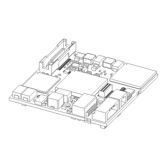
XETK-V1.0A (left) and XETK-V1.0B (right) The XETK-V1.0 is an emulator probe for ECU.s with a Nexus (JTAG) debug inter- face that runs at 3,3 V or below. The XETK-V1.0 offers the opportunity to per- form measurement of variables via the Nexus (JTAG) debug interface. -
Page 15: Features
• Permanent storage of configuration in Flash • Configurable ETK chip select • Enable or disable the ETK by ECU software • Firmware update (programming of the logic device) through software HSP; removal of XETK or ECU not necessary XETK-V1.0 - User’s Guide... - Page 16 ETAS Introduction For more technical data on the XETK-V1.0 consult the chapter "Technical Data" on page 39. XETK-V1.0 - User’s Guide...
-
Page 17: Hardware Description
ETAS Hardware Description Hardware Description In this chapter, the function blocks of the XETK-V1.0 are explained in detail. VertiCal Interface Concept 4.1.1 Overview The VertiCal interface is a new concept to connect the development ECU with an ETK. It uses a microcontroller in a chip scale package (CSP). This chip is fully compatible to the standard microcontroller. -
Page 18: Vertical Base Board
VertiCal Base Board (fitted with Pin Array/ BGA Adapter, Side View) 4.1.3 Typical Usage The standard ECU microcontroller is replaced by the VertiCal base board with the same dimensions and the same pinout. The VertiCal base board connects the ECU with the XETK-V1.0. XETK-V1.0 - User’s Guide... -
Page 19: Architecture
A flash memory is available for permanent storage of the adjusted parameters (program data). The 100 Mbit/s XETK Ethernet interface provides communication with the PC. The power supply for the XETK-V1.0 is provided by a switch mode power supply, to minimize power dissipation. XETK-V1.0 - User’s Guide... -
Page 20: Microcontroller Interface
ETK memory. ETK memory chip select (/CS_ETK) can be configured to any of /CS[3:0] Note This chip select must not be used by another external memory (e.g. Flash or RAM). /CS1 is not available for VertiCal base boards with MPC5553 microcontroller. XETK-V1.0 - User’s Guide... -
Page 21: Vertical Connector
Fig. 4-7 System with internal and external Memory (e.g. MPC5534) VertiCal Connector The VertiCal connector interfaces the XETK-V1.0 with the ECU and provides access to the microcontrollers external bus and Nexus (JTAG) interface. Data Emulation and Data Measurement The complete data emulation and measurement data memory consists of two 1 MByte pages (Fig. -
Page 22: Data Emulation Memory
The measurement data memory must be located within the address space of the data emulation and measurement data memory. It can have variable size. The measured data acquired from the PC via the XETK-V1.0 Ethernet interface can be stored here. -
Page 23: Fig. 4-9 Division Of The 128 Byte Trigger Segment
128 Byte limit). This limit is known as the trigger segment address. Fig. 4-9 "Division of the 128 Byte Trigger Segment" shows the configuration of the 128 Byte trigger segment. The XETK-V1.0 provides an extended trigger segment with up to 48 direct 16-bit hardware triggers. Note The unused address areas within the trigger segment are reserved for future applications and must not be used for other purposes. -
Page 24: Data Retention In Data Emulation Memory
Code Flash Memory The program code is not emulated by the XETK-V1.0. The program code is stored in the ECU Flash memory ("on chip" and/or external) and is not modified by the XETK-V1.0. -
Page 25: Power Supply
All necessary voltages are created through switching power supplies which minimizes heat build-up. The power supply of the ECU is not affected by the XETK-V1.0. An automatic switch ensures that the power supply of the XETK-V1.0 is automatically switched on and off. - Page 26 Additionally the through-hole solder pad CON3 can be used to connect a power supply U . The power supply on CON3 must use the GND of CON2 (refer to Batt2 chapter ). Pin CON2 Signal Description Battery Supply Voltage for ETK Batt Ground XETK-V1.0 - User’s Guide...
-
Page 27: Xetk Ethernet Interface
ETAS module is required for the access to the ECU. The interface is a standard full duplex 100Base-TX Ethernet interface. The XETK Ethernet interface is integrated in the ETAS IP world with automatic IP manage- ment and supports the open automotive "Universal Measurement and Calibra- tion"... -
Page 28: Nexus (Jtag) Interface
ETAS Hardware Description 4.10 Nexus (JTAG) Interface The XETK-V1.0 features a Nexus (JTAG) debugging interface connector (Mictor 38 pin) as specified in the "The Nexus 5001 Forum - Standard for a Global Embedded Processor Debug Interface, Version 2.0". Nexus Connector Fig. -
Page 29: Status Leds
ETAS Hardware Description 4.11 Status LEDs There are three LEDs displaying the operating status of the XETK-V1.0 (Fig. 4-16 on page 29). Fig. 4-16 Status LEDs State Meaning XETK-V1.0 is supplied with power and active (i.e. the ECU is switched on or the ETAS calibration and development sys- tem is connected and ready to communicate with the XETK- V1.0) -
Page 30: Braindead Flashing
It is not required that a programming routine is present in the ECU - the memory may be empty or corrupted. The XETK-V1.0 suppots Braindead Flashing via Nexus (JTAG) debug interface for all MPC5500 family microcontrollers. It is recommended as standard method for all new projects. -
Page 31: External Watchdog Disable
ECU is clean and smooth and to prevent corruption of data stored in the ETK. To accomplish this the XETK-V1.0 senses the VDDE2/3 of the ECU. This allows it to detect when the ECU is off and forward this information to INCA. In addition, it allows the ETK to enter the power save mode if the PC is off or unplugged. -
Page 32: Installation
ETAS Installation Installation In this chapter, the hardware installation of the XETK-V1.0 is described. CAUTION! The XETK can be damaged or destroyed! Some components of the interface board may be damaged or destroyed by electrostatic discharges. Please keep the board in its ... -
Page 33: Vertical Base Board Mounted On Ecu Pcb
(* ) Not delivered with XETK-V1.0 Fig. 5-2 XETK-V1.0 Connection to the ECU with Socket/Adapter The VertiCal base board fitted with a "BGA adapter" connector allows connec- tion and removal from an ECU development PCB which has been fitted with a compatible "BGA receiver"... -
Page 34: Wiring
Wiring - XETK Ethernet Interface The XETK Ethernet interface can directly connected to the PC. No additional ETAS module is required for the access to the ECU. Note The XETK Ethernet interface is not compatible with the ETK interfaces in mod- ... -
Page 35: Power Supply
Fig. 5-5 Wiring - Permanent Power Supply inside ECU not available Isolated Power Supply inside ECU The XETK-V1.0 does not require a galvanically isolated power supply. For special applications ETAS offers the isolated power supply ETP2. Pow er Supply Connect or... -
Page 36: Xetk Configuration
"XETK mode initialized". Always reconfigure the XETK after is was used as RAM adaptor to avoid unexpected behaviour of INCA. This feature allows it to use the XETK-V1.0 as a RAM extension. The pos- sible states are: – XETK mode initialized: The XETK is used in the normal way. - Page 37 • Initialization Pattern Address (Field [4 byte]) Defines the address the XETK will write a 4 byte Initialization Pattern to when the ECU comes out of reset. The address must be a physical address within the Emulation RAM of the XETK. XETK-V1.0 - User’s Guide...
- Page 38 • Initialization Pattern (Field [4 byte]) Defines the 4 byte pattern the XETK will write to the Initialization Address, if enabled, when the ECU comes out of reset. – n (0x00000000 to 0xFFFFFFFF) The default value is "0xFFFFFFFF". XETK-V1.0 - User’s Guide...
-
Page 39: Technical Data
The “Technical Data” chapter contains a summary of all technical data, pin assignments and hints to system requirements for operating the XETK-V1.0. Note The XETK-V1.0 can be shipped in the two different mechanical versions XETK- V1.0A and XETK-V1.0B (refer to chapter 7.11.1 on page 49 and chapter 7.11.2 on page 50). -
Page 40: Environmental Conditions
Batt Batt from ECU; T = 20 °C; I = 0 mA at pin VDDSRAM_OUT 1) The XETK-V1.0 implements reverse voltage protection in the same range and may be used only with central load dump protection. Configuration Item Characteristics Configuration Project-specific configuration for... -
Page 41: Xetk Ethernet Interface
XETK Configuration Tool (default IP address: 192.168.40.16) Cable length max. 30 m / 100 ft Ethernet interface DC decoupling Note To ensure successful initialization of the network card of your PC, refer to chap- ter 7.1.2 on page 39. XETK-V1.0 - User’s Guide... -
Page 42: Microcontroller Bus Interface
: Delay of ECU reset through ETK without transferring the Flash Reset1 present, U will be switched on) Batt VDDE2/3 : max. delay of ECU reset through ETK Reset2 and U will be switched on) Batt VDDE2/3 XETK-V1.0 - User’s Guide... -
Page 43: Electrical Characteristics
Electrical Characteristics C_ADDR[30...12] = 2.5 V 0.69 1.61 -5/+5 VDDE2/3 = 3.3 V -5/+5 VDDE2/3 C_DATA[15..0] = 2.5 V; 0.55 1.75 -5/+5 VDDE2/3 = -9 mA; = 9 mA = 3.3 V; -5/+5 VDDE2/3 = -12 mA; = 12 mA RD_/WR;... - Page 44 TCK; TMS = 1.8 V; 1.25 -1630/ VDDE7 = -6 mA; -1820 = 6 mA = 2.5 V; -2280/ VDDE7 = -6 mA; -2520 = 12 mA = 3.3 V; -2980/ VDDE7 = -18 mA; -3320 = 18 mA = 1.8 V; 1.25 -25/...
- Page 45 JCOMP = 1.8 V; 1.25 -1630/ VDDE7 = -6 mA; -1820 = 6 mA = 2.5 V; -2280/ VDDE7 = -6 mA; -2520 = 12 mA = 3.3 V; -2980/ VDDE7 = -18 mA; -3320 = 18 mA = 1.8 V -20/+20 VDDE7 = 2.5 V...
- Page 46 MDO[11..1]; /EVTI; /EVTO; MCKO; /MSEO[1..0] Clockout VertiCal plug and Mictor connector not considered; PCB 1 pF/cm...
-
Page 47: Switching Characteristics
ETAS Technical Data 7.10 Switching Characteristics The following diagrams show the timings the XETK-V1.0 can process. Note All timings are measured at a reference level of 1.5 V. Output signals are mea- sured with 10 pF to ground and 50 to 1.5 V. - Page 48 ETAS Technical Data Para. Description Unit Data valid before end of write Data valid after end of write Write enable pulse width XETK-V1.0 - User’s Guide...
-
Page 49: Mechanical Dimensions
The reference measure for all drawings is millimeter. 7.11.1 XETK-V1.0A Fig. 7-3 XETK-V1.0A Dimensions - Top View Dimension Millimeters Inches 54.00 2.126 54.00 2.126 27.00 1.063 27.00 1.063 27.00 1.063 27.00 1.063 Fig. 7-4 Mechanical Dimensions XETK-V1.0A: Microcontroller with Socket Adapter mounted XETK-V1.0 - User’s Guide... -
Page 50: Xetk-V1.0B
0.211 1.70 0.067 6.10 0.240 7.11.2 XETK-V1.0B Fig. 7-5 XETK-V1.0B Dimensions - Top View 69.00 2.717 54.00 2.126 34.50 1.358 30.75 1.211 30.75 1.211 34.50 1.358 27.00 1.063 23.25 0.915 23.25 0.915 27.00 1.063 3.50 0.138 XETK-V1.0 - User’s Guide... - Page 51 ETAS Technical Data Fig. 7-6 Mechanical Dimensions XETK-V1.0B: Microcontroller with Socket Adapter mounted Dimension Millimeters Inches 2.00 0.079 5.36 0.211 1.70 0.067 6.10 0.240 XETK-V1.0 - User’s Guide...
-
Page 52: Pin Assignment
M CK /M S /RDY STBY /M S COM P TM S RESET /RST BOOT CFG0 CANA BOOT CFG1 CANA BOOT SCLA SCLA GPIO GPIO A27 A26 GPIO E2/3 E2/3 /WE~ DATA~ Fig. 7-7 VertiCal Connector XETK-V1.0 - User’s Guide... - Page 53 C_ADDR21 C_ADDR22 C_ADDR23 C_ADDR24 C_ADDR25 C_ADDR26 C_ADDR27 C_ADDR28 C_ADDR29 C_ADDR30 /C_CS0 Chip Select /C_CS1 Chip Select /C_CS2 Chip Select /C_CS3 Chip Select C_RD/WR Read/Write /C_WE0 Write/Byte Enable /C_WE1 Write/Byte Enable /C_OE Output Enable /C_TS Transfer Start XETK-V1.0 - User’s Guide...
- Page 54 MDO6 MDO7 MDO8 MDO9 MDO10 MDO11 MDO12 Nexus Message Data Out (reserved for future extension) MDO13 MDO14 MDO15 /MSEO0 Nexus Message Start/End Out /MSEO1 /EVTI Nexus Event Input /EVTO Nexus Event Output /RDY Nexus Ready Output XETK-V1.0 - User’s Guide...
- Page 55 ECU Bus Supply Voltage B4, B8, B12, B16, VDDE7 Microcontroller Supply Voltage (Nexus) B20, E21 F21, G22 VDDEH6 Microcontroller Supply Voltage (Reset) R21, T21 VDDEH8 Microcontroller Supply Voltage (GPIO205 & ETRIG[1:0]) V21, W21 TPWR Unregulated Battery Voltage Input XETK-V1.0 - User’s Guide...
- Page 56 U21, V22, AA2, AA6, AA1, AA16, AA20, AB1, AB6, AB11, AB16, AB19, AB21 V1, W22 Reserved Reserved for future extensions A2, A22, AB22 Locating Pins No electrical function = not used by XETK-V1.0 = not connected XETK-V1.0 - User’s Guide...
-
Page 57: Nexus (Jtag) Connector
MDO2 TDET/WDT Watchdog disable input and tool detect output MDO1 GPIO207 MCU GPIO MDO0 UBATT Optional XETK-V1.0 supply voltage, standard supply path is flying lead /EVTO UBATT Optional XETK-V1.0 supply voltage, standard supply path is flying lead MCKO GPIO206 MCU GPIO... - Page 58 Power Supply for MCU internal RAM /MSEO0 Note The specification of the Nexus (JTAG) interface bases on the "Nexus 5001 Forum™ Standard for a Global Embedded Processor Debug Interface". This standard was adapted by Freescale (Freescale Semiconductor Application Note AN 2614). XETK-V1.0 - User’s Guide...
-
Page 59: Cables And Accessories
XETK ECU Adapter Cable, 100MBit/s, shield connected to ECU-housing (lead- through diameter for cable: 10mm), 0m6 length, shield bare for cable gland, isolated to the XETK. Usable for ECUs with shielded housing. Product Length Order-No CBAM240.1-0m6 0.6 m F 00K 105 792 XETK-V1.0 - User’s Guide... -
Page 60: Pc Interface Cable
CBAE200.2 Adapter Cable Fig. 8-4 CBAE200.2 Adapter Cable Cable adapter to connect CBE230 cable to the PC over an RJ45 connector. The CBAE200.2-1m20 supports Gigabit Ethernet. Product Length Order-No CBAE200.2-1m20 1.20 m F 00K 105 760 XETK-V1.0 - User’s Guide... -
Page 61: Etas Module Interface Adapter Cable
Cables and Accessories ETAS Module Interface Adapter Cable 8.3.1 CBE230.1 Cable Fig. 8-5 CBE230.1 Cable Gigabit Ethernet connection cable for ETAS devices. IP67 rated Lemo connectors on both sides. Gigabit Ethernet cable with power supply. Product Length Order-No CBE230.1-3 F 00K 105 757 CBE230.1-8... -
Page 62: Cable K70
Cable K70 Fig. 8-8 Power Supply Cable K70 Millimeters Inches 2000 78.74 8.4.3 Cable KA50 Fig. 8-9 Power Supply Cable KA50 Millimeters Inches 7.87 1.97 8.4.4 Cable CBM200 Fig. 8-10 Power Supply Cable CBM200 Millimeters Inches 3.94 XETK-V1.0 - User’s Guide... -
Page 63: Ordering Information
Ordering Information Ordering Information XETK-V1.0 Type Order-No. Note XETK-V1.0A F-00K-105-755 XETK-V1.0 emulator probe with 1 MByte emulation memory per page, for Freescale MPC5500 - VertiCal Base Boards; standard XETK-V1.0 variant XETK-V1.0B F-00K-105-756 XETK-V1.0 emulator probe with 1 MByte emulation memory per... -
Page 64: Sockets Ecu - Vertical Base Board
Power Supply Order Name Short Name Order Number ETK power supply for 6 - 36 V DC input ETP1 F 00K 000 624 Power Supply Interface for ETK ETP2 F 00K 104 010 XETK-V1.0 - User’s Guide... -
Page 65: Cables
Cables Note The cables showed in chapter "Cables and Accessories" on page 59 are not included in the XETK-V1.0 delivery. Note The screws for mounting ECU adapter cables are not included in the cable delivery. They need to be ordered separately. -
Page 66: Power Supply Cables
External Power Supply Cable for ETKs, Y 261 A24 Lemo 0B FGG # open wires (2fc-1c), ETK Power Supply Cable for External KA50 F 00K 000 Supply, with Filter Coil, Lemo 0B EGG # open wire (2fc-1c), 0m2 XETK-V1.0 - User’s Guide... -
Page 67: Etas Contact Addresses
Germany WWW: www.etas.com ETAS Subsidiaries and Technical Support For details of your local sales office as well as your local technical support team and product hotlines, take a look at the ETAS website: ETAS subsidiaries WWW: www.etas.com/en/contact.php ETAS technical support WWW: www.etas.com/en/hotlines.php... -
Page 68: List Of Figures
Status LEDs....................29 Fig. 5-1 XETK-V1.0 soldered Connection to the ECU ..........32 Fig. 5-2 XETK-V1.0 Connection to the ECU with Socket/Adapter ......33 Fig. 5-3 Wiring - XETK Ethernet Interface..............34 Fig. 5-4 Wiring - Permanent Power Supply inside ECU available ....... 35 Fig. - Page 69 CBAE330.2 Adapter Cable................61 Fig. 8-7 Power Supply Cable ETV ................61 Fig. 8-8 Power Supply Cable K70 ................62 Fig. 8-9 Power Supply Cable KA50 ................. 62 Fig. 8-10 Power Supply Cable CBM200 ..............62 XETK-V1.0 - User’s Guide...
-
Page 70: Index
INCA 36 CBE230.1 Cable 61 Interface Code Microcontroller 20 Flash Memory 24 Nexus (JTAG) 28 Code Flash Memory 24 Introduction 14 Configuration 40 Isolated Power Supply 35 Configuration Parameter 36 LED 29 Data Emulation Memory 22 XETK-V1.0 - User’s Guide... - Page 71 XETK Ethernet Interface 27 Rapid Prototyping 41 REACH regulation (EU) 13 Read Timing 47 Recycling 12 Reset 31 RoHS conformity China 12 European Union 12 Safety notices Identification 6 Safety precautions 8 Scope of supply 7 XETK-V1.0 - User’s Guide...
Need help?
Do you have a question about the XETK-V1.0 and is the answer not in the manual?
Questions and answers