Table of Contents
Advertisement
Quick Links
Advertisement
Chapters
Table of Contents

Subscribe to Our Youtube Channel
Related Manuals for ETAS ES921.1


Summary of Contents for ETAS ES921.1
- Page 1 ETAS ES921.1 CAN Module User Guide...
- Page 2 The data in this document may not be altered or amended without special noti- fication from ETAS GmbH. ETAS GmbH undertakes no further obligation in relation to this document. The software described in it can only be used if the customer is in possession of a general license agreement or single license.
-
Page 3: Table Of Contents
6.1.2 Installing the ES921.1 in the ES910 Module ......22 Disassembly ............24 6.2.1... - Page 4 ES921.1 Firmware ........
-
Page 5: About This Document
Presentation of Instructions The target to be achieved is defined in the heading. The necessary steps for his are in a step-by-step guide: Target definition 1. Step 1 2. Step 2 3. Step 3 > Result ES921.1 - User Guide... -
Page 6: Typographical Conventions
ETAS About this Document Typographical Conventions Hardware Bold Menu commands, buttons, labels of the product Italic Emphasis on content and newly introduced terms Presentation of Supporting Information NOTE Contains additional supporting information. ES921.1 - User Guide... -
Page 7: About This Manual
(see chapter 9.1 on page 38). Additional cables and adapters can be obtained separately from ETAS. A list of available accessories and their order designation is located in chapter “Acces- sories” on page 38 of this manual or in the ETAS product catalog. -
Page 8: Basic Safety Notices
ETK and XETK and also one interface for Daisy Chain modules (ES4xx/ES63x/ ES93x modules). If additional interfaces are required, the extension slot of the ES910.3-A can be used with the ES920.1 FlexRay Module, the ES921.1 CAN Module or with the ES922.1 CAN FD Module. ES921.1 - User Guide... - Page 9 The module is not suitable for installation in the engine com- partment and similar environments. For use in other application areas, please contact your ETAS contact partner. Requirements for the technical state of the product The product is designed in accordance with state-of-the-art technology and recognized safety rules.
- Page 10 Connect the power cable only with a suitable vehicle battery or with a suitable lab power supply! The connection to power outlets is not allowed! To prevent an inadvertent insertion in power outlets, ETAS recommends to equip the power cables with safety banana plugs in areas with power outlets.
- Page 11 • Adhere to the maximum permissible cable lengths! • Do not use any damaged cables! Cables may be repaired only by ETAS! • Never apply force to insert a plug into a socket. Ensure that there is no contamination in and on the connection, that the plug fits the socket, and that you correctly aligned the plugs with the connection.
- Page 12 Heat concentration on the top of the module. The electronics can be damaged due to overheating. Do not stack several ES910.3-A modules on top of each other. When stacking the ES910.3-A with other ETAS modules, it always has to be on top. Assembling (interconnecting) the modules •...
- Page 13 CAUTION Damage to the module and loss of properties based on IP30! Do not open or change the module housing! Work on the module housing may only be performed by ETAS. Potential equalization CAUTION Potential equalization in the vehicle is possible via the shield of the...
-
Page 14: Hardware Description
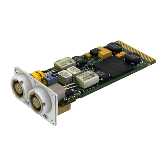
The ES921.1 CAN Module is an extension module for the ES910 Rapid Proto- typing Module. NOTE Operating the ES921.1 is possible in the extension slot of the ES910.2 and the ES910.3-A. The CAN module ES921.1 has two CAN bus interfaces (High- and Low-Speed). -
Page 15: General Features
Part of the ETAS tool suite – supported by INCA/INCA-EIP, INTECRIO, ASCET-RP, HSP 4.2.2 Rapid Prototyping Functions The CAN interfaces of the ES910 and ES921.1 are comparable in terms of their functions. Important rapid prototyping functions of the ES921.1: •... -
Page 16: Ports
ETAS Hardware Description 4.2.4 Ports The CAN ports CAN1 and CAN2 are on the front of the ES921.1. ES921.1 CAN1 CAN2 Fig. 4-2 ES921.1Ports 4.2.5 A common LED T is assigned to the interfaces CAN1 and CAN2. When the ES910 is powered on, this LED displays the following functional states:... -
Page 17: Functional Description
Block Diagram of the ES921.1 CAN Interface (CAN1, CAN2) The ES921.1 has two CAN interfaces. One of the CAN interfaces is routed to the two 8-pin CAN1 and CAN2 connectors (Lemo sockets) on the front panel. CAN1 and CAN2 are independent CAN interfaces with independent connec- tions and CAN controllers. -
Page 18: Bus Termination Resistor
In the ES921.1, two relatively high-impedance termination resistors of 2.26 kOhm each (RTH, RTL) are integrated for the Low-Speed CAN link. This guarantees that, in a terminated CAN network, the ES921.1 does not have a great influence on the sum of the terminations of the overall system. This should, however, be checked regardless particularly with lab networks or with tests in existing networks. -
Page 19: Wake-Up" Function
The “Sleep” condition is fulfilled as soon as no signals are transferred on the CAN buses. 5.3.3 Configuration The “Wake-Up” and “Sleep” behavior of the ES921.1 is configured in the web interface of the ES910 module (see section 6.4.2 on page 27). ES921.1 - User Guide... -
Page 20: Firmware
5.4.2 Firmware Update The firmware of the ES921.1 can be updated by the user so that future versions of the module can also be implemented. The firmware update is executed on the connected PC using the HSP service software. -
Page 21: Getting Started
ES921.1. Assembly The extension slot on the front of the ES910 has a removable front panel. You have to replace this front panel with the ES921.1 module if you want to use the CAN interfaces. 6.1.1 Removing the Front Panel of the ES910 Extension Slot To install the ES921.1 in the ES910, you need a flat-bladed screwdriver (width... -
Page 22: Installing The Es921.1 In The Es910 Module
1. Place the ES910 on a solid surface. CAUTION Damage to the ES910 possible! The ES910 module must not be stood on its back when the ES921.1 is installed in the ES910 module. 2. Position the ES921.1 in front of the extension slot of the ES910 module. - Page 23 The contact spring in the extension slot of the ES910 must not be damaged when the ES921.1 is installed. 4. Press on the front panel of the ES921.1 from the front. The connectors of the ES921.1 and the ES910 click into place.
-
Page 24: Disassembly
3. Place the ES910 on a solid surface. CAUTION Damage to the ES910 possible! The ES910 module must not be stood on its back when the ES921.1 is being removed. The mounting screws of the extension slot must not fall into the module. -
Page 25: Attaching The Front Panel Of The Es910 Extension Slot
1. Position the front panel in front of the extension slot of the ES910 module. Align the back of the front panel with the front of the housing of the ES910. 2. Use the screws the ES921.1 was attached with to screw on the front panel. CAUTION Damage to the ES910 possible! The ES910 module must not be stood on its back when the front panel is being attached. -
Page 26: Wiring
ETK connecting cable CBM150 Configuring the ES921.1 The ES921.1 is configured on your PC in the application program; the “Wake Up” function of the ES921.1 is configured in the web interface of the ES910 module. 6.4.1 Web Interface The web interface of the ES910 consists of a home page, a page for custom- ized configuration of the ES921.1 for the “Wake Up”... -
Page 27: Configuring The "Wake Up" Function Of The Es921.1 Module
Troubleshooting Please observe the LEDs which provide information on the functions of the ports and the ES921.1 (see the section “LED” on page 16) to be able to judge the operational state of the ES921.1 as well as troubleshooting measures. -
Page 28: Technical Data
Technical Data This chapter describes the pin assignment, general data and electrical data of the ES921.1. General Data This section contains general data on the ES921.1. 7.1.1 Identifications on the product The following symbols are used for identifying the product:... -
Page 29: Rohs Conformity
People's Republic of China with a China RoHS label attached to the product or its packaging. CE conformity With the CE mark attached to the product or its packaging, ETAS confirms that the product corresponds to the product-specific, applicable directives of the European Union. -
Page 30: Product Return And Recycling
Attributions List" at the ETAS website www.etas.com. System Requirements 7.8.1 Hardware To operate the modules, an ES910 Rapid Prototyping Module is necessary. NOTE Operating the ES921.1 is possible in the extension slot of the ES910.2 and the ES910.3-A. ES921.1 - User Guide... -
Page 31: Software
ETAS Technical Data 7.8.2 Software ES921.1 mounted in the ES910.2 To configure the ES921.1 mounted in the ES910.2 and for control and data acquisition, you need software in the following versions and higher: Support in Application Software Application Classifi- INCA... -
Page 32: Es921.1 Firmware
CAN Interfaces CAN1 and CAN2 2 independent interfaces, galvanically isolated from each other, every interface can be configured indi- vidually (High-Speed / Low-Speed CAN) Protocols CAN V2.0a (Standard Identifier), CAN V2.0b (Extended Identifier) Controller IP-Core (FPGA) ES921.1 - User Guide... - Page 33 < 150 ns/V Differential input resistor R i,diff = 10 kOhm At least two signal edges of the same polarity must be within a time of 100 ms. Miscellaneous Functions Wake-Up, Sleep Status display of CAN bus ES921.1 - User Guide...
-
Page 34: Pin Assignment
ETAS Technical Data 7.10 Pin Assignment NOTE All ports are shown with a view of the ports of the ES921.1. All shields are at case potential. Fig. 7-2 CAN Interface (CAN1 and CAN2) Signal Meaning Reserved CAN_LOW CAN_GND Reserved Reserved... -
Page 35: Cables And Accessories
Cables and Accessories The “Cables and Accessories” chapter contains an overview of the available cables and accessories. NOTE Only use ETAS cables at the interfaces of the ES921.1. The maximum admis- sible cable lengths must be adhered to. CAN Cable 8.1.1... -
Page 36: Cbcx130 Cable
Cable for CAN, SIC, DSUB, 2 m F 00K 000 384 8.1.5 CBAC140 Cable Side A Side B Fig. 8-5 CBAC140 Cable Order Name Short Name Order Number Cable SubD - Lemo 2B FGG (9fc-10mc, CBAC140-3 F 00K 103 783 3 m) ES921.1 - User Guide... -
Page 37: Cbac150 Cable
2.5 m) CAN Termination Resistor 120 Ohm Side A Side B Fig. 8-7 CBCX131-0 Termination Resistor Order Name Short Name Order Number Cable SubD - SubD (9fc-9mc, 0 m), CBCX131-0 F 00K 103 786 120 Ohm Resistor ES921.1 - User Guide... -
Page 38: Ordering Information
ETAS Ordering Information Ordering Information ES921.1 Order Name Short Name Order Number ES921.1 CAN Module (2-CH) ES921.1 F 00K 105 672 Package Contents ES921.1 CAN Module (2-CH), Cable: 2 x K106, Termination resistor: 2 x CBCX131-0, ES900_Screws) List "Content of this Package",... -
Page 39: Contact Information
Germany Internet: www.etas.com ETAS Subsidiaries and Technical Support For details of your local sales office as well as your local technical support team and product hotlines, take a look at the ETAS website: ETAS subsidiaries Internet: www.etas.com/en/contact.php ETAS technical support Internet: www.etas.com/en/hotlines.php... -
Page 40: Figures
Fig. 6-1 Wiring the ES921.1 and ES910 Modules ....... . .26 Fig. -
Page 41: Index
Hardware description ....14 Standards ......28 ES921.1 - User Guide... - Page 42 Wiring ......26 XCP on CAN Bypass ....15 ES921.1 - User Guide...
Need help?
Do you have a question about the ES921.1 and is the answer not in the manual?
Questions and answers