Advertisement
Quick Links
Advertisement

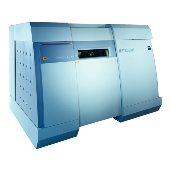
Summary of Contents for Zeiss METROTOM
- Page 1 Technical Services Installation Instructions METROTOM...
- Page 3 The supervisory authority can stipulate further conditions which must be fulfilled as a prerequisite for the notice of ap- proval. According to § 18 of the RöV, the METROTOM must be inspected by an authorized expert after 5 years of operation at the latest (recurring inspections).
- Page 4 Check the floor and ceiling loading capacity of all transport paths leading to the installation site. The doorways and trans- port paths must be at least 10 cm wider and higher than the METROTOM assemblies to be transported, including the transport vehicle.
-
Page 5: General Protective Measures
Temperature conditions required to operate the METROTOM: The measuring uncertainty specified for the METRONOM is guaranteed under the following conditions: 1. The measuring data correction program is used and the workpiece and METROTOM temperatures are entered along with the temperature expansion coefficient of the workpiece material. - Page 6 A measurement is required to assess the magnitude of the floor vibrations. If you would like to have this service performed for you, contact Carl Zeiss in Oberkochen. In any case, the measured result must be made available.
- Page 7 30 mA Control cabinet 3.3 Electric power supply parameters In order to ensure trouble-free data communication between the METROTOM and the data station, the power supply should have the following parameters. Line voltage – Controller: 3/N/PE 400/230VAC (±10%) for the USA: 3/PE 208VAC ±10 % 50/60 Hz...
- Page 8 Contact us if you require this service. We will be glad to advise you and recommend suitable measures. A separate stub cable from the main distributing frame to the connecting point of METROTOM is sufficient in most cases. 3.7 Machine parameters –...
-
Page 9: Compressed Air Supply
Connection point for compressed air Our service engineer requires a connection point to connect the METROTOM to the compressed air supply. You should provide this connection point as shown in the brochure. The machine-side connection (9x2.5) is provided for compressed air hoses with an internal diameter of 9 mm. - Page 10 3.14 Moving the METROTOM to another location To prevent damage to the machine, our system specialists should be consulted before it is moved to another location. Page Installation Instructions...
- Page 11 4. Transport crates Note on transport crates: The METROTOM is delivered on transport pallets wrapped in insulated packaging. It is delivered in a transport crate only when shipped by air cargo or overseas. Dimensions in mm (maximum) Tare weight (kg) Max.
- Page 12 Supporting surface: 110 mm diam. 2675 *Average pressure placed on contact surfaces: 212 N/cm calculated from the net weight of the METROTOM and the max. permissible workpiece weight distributed over the base of the machine jacks of 95 cm per jack.
- Page 13 = Cable entry on control cabinet ➅ ➀ data station (national voltage) = Compressed air supply on METROTOM (air hose entry from below, optionally from above) ➆ = Computer station with 2x PC with monitor, keyboard and mouse ➂ = Network connection = Min.
- Page 14 7. Fastening holes on rotary table α Ø 300 M8 fastening hole Radius Angle M8 fastening hole Radius Angle Pos. No. “R“ “α“ Pos. No. “R“ “α“ 55 mm 90 mm 60 mm 107.5 mm 72.5 mm 125 mm Page Installation Instructions...
- Page 16 Carl Zeiss 73446 Oberkochen 600061-1118.020 Printed in Germany I-SD 06.08...


Need help?
Do you have a question about the METROTOM and is the answer not in the manual?
Questions and answers