
Related Manuals for Zeiss INTRABEAM


Summary of Contents for Zeiss INTRABEAM
- Page 1 ZEISS ® INTRABEAM Water Phantom Instructions for Use G-30-1767-en Version 6.2 2022-02-24...
- Page 2 Store them for the entire service life of the device. • Pass them on to every subsequent owner or user of the device. Trademark INTRABEAM is a registered trademark of Carl Zeiss Meditec AG or of another company of the ZEISS Group in Germany and/or other countries. Trademark UNIDOS®...
-
Page 3: Designations And Abbreviations
Flat applicator Flat Applicator INTRABEAM Surface applicator Surface applicator Surface Applicator INTRABEAM 600 INTRABEAM 600 INTRABEAM 600 refers to the complete product, workplace and software. UNIDOS Romeo Type Electrometer UNIDOS Romeo electrometer Type TN10053-AS TN10053-AS from PTW-Freiburg. Permanently installed in the Workplace. - Page 4 INTRABEAM Water Phantom (Blank page, for your notes . . .) Version 6.2 Page 4 G-30-1767-en...
-
Page 5: Table Of Contents
INTRABEAM Water Phantom Contents Designations and abbreviations ..............3 Safety measures Key to symbols .................. 9 Hazard symbols ...................9 Information symbols..................9 Target group ...................10 Field of application ................10 Intended use .....................10 Normal use....................10 Notes for the operator..............12 Symbols and labels ................16 System overview Overview of the modules..............18... - Page 6 Important information on dose rate values ..........51 Measuring the depth dose curve with spherical applicator....53 Inserting the spherical applicator in the INTRABEAM Water Phantom ..53 Positioning the spherical applicator with the XRS probe in the Z direction ....................55 Measuring the depth dose curve, with spherical applicator and XRS probe....................
- Page 7 INTRABEAM Water Phantom Measuring isotropy without spherical applicator......56 Positioning the probe tip for isotropy measurement ........56 Positioning the rotary feedthrough ............57 Measuring isotropy..................58 Measuring isotropy with spherical applicator ........58 Positioning the applicator with the XRS probe for isotropy measurement ....................58 Recording the depth dose curve with a flat applicator or surface applicator ................60...
- Page 8 INTRABEAM Water Phantom Regulatory information..............73 Ambient conditions................73 Index Version 6.2 Page 8 G-30-1767-en...
-
Page 9: Safety Measures
INTRABEAM Water Phantom Safety measures Safety measures Key to symbols We would like to inform you about safety aspects which must be observed when handling this device. This chapter contains a summary of the most important information concerning matters relevant to instrument safety. -
Page 10: Target Group
Intended use The INTRABEAM Water Phantom is used to measure the depth dose curve and the isotropy of the XRS 4 X-ray source of the INTRABEAM system to check whether the measured values are within the expected range. Normal use... - Page 11 Using micrometer screws, you position the probe tip in the three axial direc- tions (X, Y and Z) exactly relative to the measuring chambers. For rotation of the XRS 4 X-ray source about the Z axis, the INTRABEAM Water Phantom features a unit with eight detent positions which are displaced at 45°...
-
Page 12: Notes For The Operator
Please contact ZEISS Service if you have any questions. • Only use original accessories or consumables approved by Carl Zeiss. If you wish to use other accessories ensure that Carl Zeiss or the manufacturer of the accessories have verified and confirmed that these accessories meet the respective safety standards and can be used without risk. - Page 13 INTRABEAM which are relevant for the water phantom. For further explanations on the use your INTRABEAM, please refer to the re- spective instructions for use or the product information attached to your INTRABEAM and its accessories.
- Page 14 If the XRS 4 is properly seated in the XRS mount of the rotary feedthrough (for rotary feedthrough, see page 20), the optical interlock system closes and permits the generation of X-rays. The INTRABEAM generates X-radiation only when the XRS 4 is activated.
- Page 15 INTRABEAM Water Phantom Safety measures (Blank page, for your notes . . .) Version 6.2 G-30-1767-en Page 15...
-
Page 16: Symbols And Labels
Reference number 304534-7000-600 with identification num- – CE label 0297 ber of the notified body The technical data of the INTRABEAM Water Phantom can be found in the section entitled "Device data" on page 72. Version 6.2 Page 16 G-30-1767-en... - Page 17 INTRABEAM Water Phantom Safety measures Fig. 1: Symbols and labels Version 6.2 G-30-1767-en Page 17...
-
Page 18: System Overview
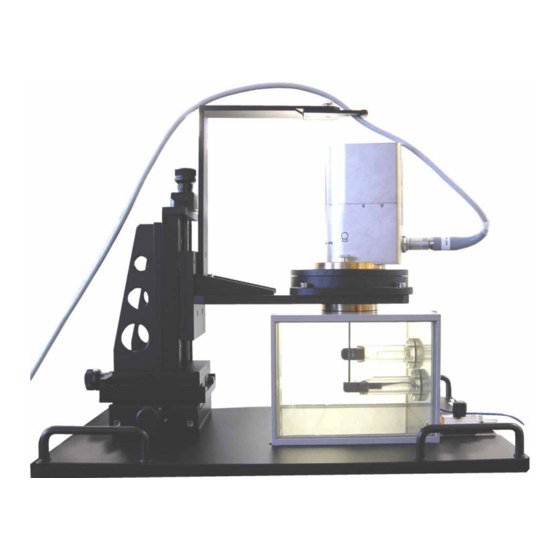
System overview INTRABEAM Water Phantom System overview Overview of the modules 1 Water tank 2 Rotary feedthrough with mount for the XRS 4 3 Cable holder, swiveling 4 Positioning unit Version 6.2 Page 18 G-30-1767-en... -
Page 19: Water Tank Module
INTRABEAM Water Phantom System overview Water tank module 1 Cover of filler opening 2 Rotary feedthrough with mount for the XRS 4 3 Radiation protection sleeves between tank and positioning device 4 Water tank wall 5 Water tank viewing window... -
Page 20: Rotary Feedthrough Module
System overview INTRABEAM Water Phantom Rotary feedthrough module 1 Rotary feedthrough with eight detent positions in steps of 45° each 2 Rotary feedthrough clamping screw This clamping screw can be used to fix the rotary feedthrough in any de- tent position. -
Page 21: Positioning Unit Module
INTRABEAM Water Phantom System overview Positioning unit module 1 Positioning in the Z direction (height) Micrometer adjustment knob with counter indicator and locking lever. The indicator has its zero position at the highest point. It shows the travel path in 1 mm steps with 2 decimal places. -
Page 22: Ionization Chamber And Ionization Chamber Holder
System overview INTRABEAM Water Phantom Ionization chamber and ionization chamber holder 1 Ionization chamber (IC) 2 Measuring window of the IC ionization chamber 3 Ionization chamber holder 4 Measuring chamber, closed with cover 5 Inserting the IC ionization chamber with the ionization chamber holder... -
Page 23: Preparations For Use
Technical conditions of use WARNING The water phantom is designed exclusively for use in combination with the INTRABEAM. The use of other control units may lead to disruptions, incorrect measured values and, as a result, incorrect radiation being administered to the patient. -
Page 24: Preparatory Workflow
Always insert the XRS 4 into the water phantom alone or with an applica- tor from the INTRABEAM range of accessories. Use the water phantom only in connection with the INTRABEAM to determine the depth dose rate or isotropy of an XRS 4. -
Page 25: Setting Up The Water Phantom
INTRABEAM Water Phantom Preparations for use Setting up the water phantom Select a stable table (laboratory bench) with a level tabletop which stands firmly and doesn't wobble. Place the water phantom on the table positioned so that you have a good view of the measuring chambers through the window. -
Page 26: Close The Measuring Chamber Again
NOTE If you use any ionization chamber holder other than the original ionization chamber holder belonging to the INTRABEAM Water Phantom, you may ob- tain false measurement results. I.e. your measurement results will deviate sig- nificantly from the values of the calibration file. -
Page 27: Reattach The Covers Of The Water Tank Properly
INTRABEAM Water Phantom Preparations for use Reattach the covers of the water tank properly. In order to ensure that the water tank is fully shielded from X-rays while the XRS 4 is in operation, you must properly insert both covers of the water tank in their guides and the respective covers of the measuring chambers must be screwed on. - Page 28 Preparations for use INTRABEAM Water Phantom (Blank page, for your notes . . .) Version 6.2 Page 28 G-30-1767-en...
-
Page 29: Operation
For the emission of X-ray radiation in the Water Phantom, your INTRABEAM must perform the prescribed verifications on the XRS 4 being used, as if for a proper treatment. In other words, for the INTRABEAM 600 see "Quality assurance". –... - Page 30 XRS 4 and the XRS mount. – Ensure that the covers of the measuring chambers are properly attached. – Switch on the INTRABEAM and let it warm up. – Record the depth dose curve: –...
- Page 31 INTRABEAM Water Phantom Operation – Place the probe tip in the optimum position in relation to the IC ionization chamber in the measuring chamber for isotropy, i.e. only raise it along the Z axis; check the positioning by measuring the current with the electrometer.
-
Page 32: Checklist
Checklist • Check your measurement setup using this checklist before you switch on your INTRABEAM and the XRS_4 starts emitting radiation: – The prescribed verifications of the XRS 4 being used were completed suc- cessfully. – The water tank is filled with deionized water up to the upper edge of the viewing window. -
Page 33: Measuring The Depth Dose Curve Without Spherical Applicator
X-ray radiation. • Switch the INTRABEAM on only when the XRS mount with the XRS 4 is properly seated in the rotary feedthrough and complete shielding is pro- vided by the water tank. - Page 34 Start the "treatment" and wait until the internal X-ray monitor indicates approx. 100%. You will find detailed explanations on how to operate the measuring functions in the Instructions for Use of your INTRABEAM (Instructions for Use "INTRABEAM 600"). You can interrupt X-ray emission by pressing the <Pause> button.
-
Page 35: Positioning The Probe Tip For Recording The Depth Dose Curve
INTRABEAM Water Phantom Operation Positioning the probe tip for recording the depth dose curve Exact positioning of the probe tip is a precondition for accurate and mean- ingful measuring results. NOTE If the water phantom is set up in an insufficiently illuminated environment, the positioning of the probe tip is difficult to recognize. -
Page 36: Positioning The Probe Tip Exactly Using The Current Measurement
Using current measurements taken with the electrometer, the probe tip can be positioned exactly above the center of the measuring window in the XY plane. Operation with the INTRABEAM 600 • Open the folding shutter of the Workplace so that the electrometer is accessible for operation. - Page 37 INTRABEAM Water Phantom Operation • Set the electrometer to current measurement. • Set the appropriate current measuring range for the electrometer. • Set the probe tip to a distance of several millimeters away from the measuring chamber in Z by adjusting the Z position.
- Page 38 Operation INTRABEAM Water Phantom NOTE If the probe tip is bent out of tolerance while being inserted in the water phantom, the XRS 4 will no longer be able to emit radiation and the quality assurance steps must be repeated.
- Page 39 INTRABEAM Water Phantom Operation – Slowly move the probe tip along the X or Y axis while observing the current value reading on the electrometer display. As long as the current value keeps increasing, go on adjusting the probe tip in this direction.
- Page 40 Operation INTRABEAM Water Phantom Checking the Z position via effort and air gap The probe tip is located in the center above the measuring window of the IC ionization chamber: • Release the locking lever on the adjusting knob for the Z axis.
- Page 41 INTRABEAM Water Phantom Operation Recording the Z position value Once the probe tip is in the optimum Z position, you can record this Z value. • Note down the Z position reading of the positioning unit as Z [mm]. You need the Z [mm] value to calculate r [mm].
- Page 42 Operation INTRABEAM Water Phantom Distance of the probe tip from the IC ionization chamber [mm] is the minimum distance of the probe tip from the IC ionization chamber at which measurement is possible. [mm] is the Z position value you noted down which is displayed on the po- sitioning unit when the probe tip is in the optimum Z position.
-
Page 43: Measuring The Depth Dose Curve
INTRABEAM Water Phantom Operation Measuring the depth dose curve When the probe tip is positioned exactly above the measuring chamber for the depth dose measurement , you can begin the radiation measurement, i.e. you can record the depth dose curve. -
Page 44: Determining The Temperature Of The Ic Ionization Chamber
Operation INTRABEAM Water Phantom NOTE If the measurements are performed outside of the specified ambient condi- tions, you may obtain falsified measurement data. • Ensure that the ambient conditions specified on page 73 are observed. Determining the temperature of the IC ionization chamber For an acclimatized measurement setup, the temperature of the IC ionization chamber can be determined by measuring the water temperature. - Page 45 INTRABEAM Water Phantom Operation (Blank page, for your notes . . .) Version 6.2 G-30-1767-en Page 45...
-
Page 46: Intrabeam 600
INTRABEAM 600 is explained below. Measuring the depth dose with the INTRABEAM 600 Starting the measurement of the depth dose curve (INTRABEAM 600) You will find detailed explanations of how to operate the software in the In- structions for Use of your INTRABEAM 600. - Page 47 INTRABEAM Water Phantom Operation Version 6.2 G-30-1767-en Page 47...
- Page 48 Operation INTRABEAM Water Phantom Recording the depth dose curve (INTRABEAM 600) Position the probe tip in equal steps in the Z axis, moving farther and farther away from the IC ionization chamber. Measure the depth dose in each new Z position.
- Page 49 INTRABEAM Water Phantom Operation (Blank page, for your notes . . .) Version 6.2 G-30-1767-en Page 49...
-
Page 50: Calculating The Dose Rate
Adjust the measured values using the correction calculation. NOTE If the user calculates the depth dose curve according to a different algorithm than the one specified by ZEISS, significant deviations from the ZEISS calibra- tion data may occur. • Always use the algorithm specified by ZEISS for calculating the depth dose curve. -
Page 51: Important Information On Dose Rate Values
Calibration v4.0 measuring method This process is thoroughly described in the present Instructions for Use (for the INTRABEAM Water Phantom). The measuring method is based on the use of an air-kerma calibrated PTW TN34013 ionization chamber. This ionization chamber is located in a specially designed watertight holder which is mounted inside a gold standard water phantom. - Page 52 Operation INTRABEAM Water Phantom The correlation between the two measurement methods is described by the following formula: Ḋ (r){TARGIT} = f'(r) . Ḋ (r){Calibration v4.0} Where f'(r) represents the conversion function. This formula has a standard deviation of max. 5.1%. The values for the conversion function itself can be obtained from the calibration documents of the XRS 4.
-
Page 53: Measuring The Depth Dose Curve With Spherical Applicator
Inserting the spherical applicator in the INTRABEAM Water Phantom Exact positioning of the applicator (with the probe tip) is a precondition for accurate and meaningful measuring results. - Page 54 Operation INTRABEAM Water Phantom • Place the applicator on the XRS mount. Make sure that the applicator en- gages properly. • Reinsert the XRS mount with the applicator in the rotary feedthrough. The exact position is determined by locating pins.
-
Page 55: Positioning The Spherical Applicator With The Xrs Probe In The Z Direction
INTRABEAM Water Phantom Operation Positioning the spherical applicator with the XRS probe in the Z direction • Calculate the distance of the applicator surface from the IC ionization chamber: + (Z ) - R iApp [mm] = Distance of the applicator surface from the IC ionization... -
Page 56: Measuring Isotropy Without Spherical Applicator
Operation INTRABEAM Water Phantom Measuring isotropy without spherical applicator The geometry of the spherical radiation emission of the probe tip is checked on an XRS 4 when measuring the isotropy. The isotropy check is performed at maximum beam current and the beam voltage selected for the respective XRS... -
Page 57: Positioning The Rotary Feedthrough
INTRABEAM Water Phantom Operation • In the position with the maximum current value, you have reached the exact Z position of the probe tip. • Secure this Z positioning using the locking lever on the adjusting knob for the Z axis. -
Page 58: Measuring Isotropy
Operation INTRABEAM Water Phantom Measuring isotropy If air bubbles have accumulated on the probe tip, you must remove them prior to the measurement, as they may negatively influence the measurement re- sult: • Use a longer spatula or a plastic or glass rod to wipe off the air bubbles. - Page 59 INTRABEAM Water Phantom Operation The procedure for inserting the spherical applicator in the water phantom is explained on page 53. • Insert the IC ionization chamber in the measuring chamber for the isotropy measurement (if this has not already been done).
-
Page 60: Recording The Depth Dose Curve With A Flat Applicator Or Surface Applicator
Operation INTRABEAM Water Phantom • Observe the current value reading on the electrometer display and move the spherical applicator further upwards. You can see that the current value increases accordingly. • If you move the spherical applicator together with the X-ray probe further upwards and the current value drops, you have passed the exact target point. - Page 61 INTRABEAM Water Phantom Operation • Pull the two covers of the water tank apart sideways over approx. 1/3 of their surface. • Loosen the screws for fixing the XRS mount in the rotary feedthrough. • Remove the XRS mount. •...
-
Page 62: Water Phantom Procedure For Depth Dose Curve Measurements Using A Flat Or Surface Applicator
Operation INTRABEAM Water Phantom Water phantom procedure for depth dose curve measurements using a flat or surface applicator The applicators are designed for radiation treatment on the surface (surface applicator) and at a depth of 5 mm (flat applicator). In the first case, the dose rate must be measured on the surface of the applicator. - Page 63 INTRABEAM Water Phantom Operation This procedure may, however, prove to be very cumbersome for the user, since the measuring chamber of the water phantom is permanently installed. This means that, every time the XRS 4 with the attached applicator is moved...
- Page 64 Operation INTRABEAM Water Phantom Centering of the XRS 4 with the applicator mounted on the measuring window of the IC ionization chamber is not easy to perform, since the flat dose distribution would not take into account any maximum value over the X- Y surface of the applicator.
- Page 65 INTRABEAM Water Phantom Operation • Calculate the distance between the applicator surface and the IC ioniza- tion chamber: + (Z ) - Z iApp [mm] = distance between applicator surface and IC ionization chamber iApp [mm] = smallest distance between probe tip and IC ionization chamber...
- Page 66 Operation INTRABEAM Water Phantom Applicator size Max. depth (Z) [mm] [mm] 50 (for flat only) 60 (for flat only) • Be careful not to place the applicator too deep (in the Z axis), as there is a risk of it colliding with the ionization chamber holder.
-
Page 67: Care And Maintenance
INTRABEAM Water Phantom Care and maintenance Care and maintenance Safety inspection To prevent any impairment of the system's safety as a result of aging, wear etc., the operating company must ensure, in accordance with the applicable national regulations, that the regular technical safety checks defined for this system are performed on schedule and to the stipulated extent. -
Page 68: Transporting The Water Phantom
• If the water phantom is transported over long distances (e.g. relocation, return for repair, etc.), always use the original packaging or special return packaging. Please contact your dealer or ZEISS Service if necessary. Care of the water phantom WARNING If the XRS 4 is still seated in the XRS mount and is connected during care and maintenance work, unintentional irradiation may occur. -
Page 69: Calibration And Maintenance Of The Positioning Unit
INTRABEAM Water Phantom Care and maintenance Calibration and maintenance of the positioning unit Calibrating the positioning unit • Move the Z-axis slide upward so that you can position the gage block be- tween the bottom of the slide and the baseplate of the bracket. -
Page 70: Maintenance Of The Positioning Unit
Care and maintenance INTRABEAM Water Phantom Maintenance of the positioning unit NOTE If the specified maintenance intervals are not observed, the motion of the po- sitioning unit may become stiff and setting will become more difficult. • Make sure that the positioning unit is lubricated at the specified intervals Lubricants mainly consist of base oil and thickener. -
Page 71: Disposal
INTRABEAM Water Phantom Care and maintenance Disposal NOTE • Dispose of the water phantom in compliance with your pertaining na- tional regulations. • If you have any questions, please contact the manufacturer or your sup- plier. Version 6.2 G-30-1767-en Page 71... -
Page 72: System Data
System data INTRABEAM Water Phantom System data Ordering data Designation Cat. No. Water phantom, complete with IC ionization chamber, type 34013 304534-7000-600 Water phantom, complete without IC ionization chamber 304534-7000-610 IC ionization chamber, type 34013 304534-7000-620 Technical data Water phantom... - Page 73 INTRABEAM Water Phantom System data Regulatory information Description Labeling Classification The medical device is classified according to Ap- pendix IX of the Medical Device Directive 93/42/EEC as Class I (with measuring functionality). CE mark The medical device complies with the essential re- quirements stipulated in Appendix I of the Medical Device Directive 93/42/EEC.
- Page 74 System data INTRABEAM Water Phantom (Blank page, for your notes . . .) Version 6.2 Page 74 G-30-1767-en...
- Page 75 INTRABEAM Water Phantom Index Index Abbreviations and designations ..............3 Acclimatization ..................32 Additional equipment ................12 Address of manufacturer ................2 Air bubbles on the probe tip ...............43, 58 Air pressure ....................29 Ambient conditions ..................73 Applicator ....................10 Applicator with the X-ray probe ...............58 Applicator, positioning for isotropy measurement ........58...
- Page 76 IC ionization chamber in the measuring chamber ........19 Information symbols .................. 9 Instructions for Use for the INTRABEAM 600 ........... 13 Instructions for Use, INTRABEAM PRS system with XRS 4 ......13 Instructions for Use, UNIDOS E ..............13 Intended use .................... 10 Interference with the system, unauthorized ..........
- Page 77 INTRABEAM Water Phantom Index Key to symbols ...................9 Legal regulations ..................12 Liability and warranty ................12 Loss of warranty ..................12 Manufacturer's address ................2 Measurement setup, checking ..............32 Measurement workflow ................29 Measuring chamber for depth dose measurement ........19 Measuring chamber for isotropy measurement .........19 Measuring chamber with cover ..............22...
- Page 78 Index INTRABEAM Water Phantom Positioning, exact ................35, 56 Preparations for use ................. 23 Preparatory workflow ................24 Preparing and handling the medical device ..........10 Probe tip ....................33 Probe tip and measuring chamber ............35 Probe tip, optimal positioning ..............29 Probe tip, positioning ................
- Page 79 INTRABEAM Water Phantom Index Technical data ..................72 Temperature of the IC ionization chamber, determination of ....44 The INTRABEAM 600 manages all INTRABEAM applicators .......46 Trademark ....................2 Training courses ..................13 Transport, on site ................23, 68 Treatment, safety during ................14 Warranty and liability ................12 Water phantom ..................10...
- Page 80 Index INTRABEAM Water Phantom (Blank page, for your notes . . .) Version 6.2 Page 80 G-30-1767-en...
- Page 81 INTRABEAM Water Phantom (Blank page, for your notes . . .) Version 6.2 G-30-1767-en Page 81...
- Page 82 Carl Zeiss Meditec AG Goeschwitzer Strasse 51-52 Email: info.meditec@zeiss.com 07745 Jena Internet: www.zeiss.com/med Germany...
Need help?
Do you have a question about the INTRABEAM and is the answer not in the manual?
Questions and answers