Table of Contents
Advertisement
Quick Links
Advertisement
Table of Contents

Related Manuals for Ruijie RG-S8600E Series


Summary of Contents for Ruijie RG-S8600E Series
- Page 1 RG-S8600E Series Switches Quick Installation Guide V1.02...
- Page 2 This document is provided “as is”. The contents of this document are subject to change without any notice. Please obtain the latest information through the Ruijie Networks website. Ruijie Networks endeavors to ensure content accuracy and will not shoulder any...
- Page 3 It is intended for the users who have some experience in installing and maintaining network hardware. At the same time, it is assumed that the users are already familiar with the related terms and concepts. Obtaining Technical Assistance Ruijie Networks Website: http://www.ruijienetworks.com/ Service Email: service_rj@ruijienetworks.com ...
-
Page 4: Product Overview
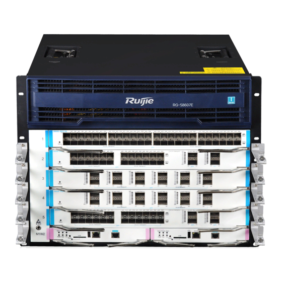
Launched by Ruijie independently, RG-S8600E series next generation core switches adopt the Full Mesh/Clos architecture and support large buffer. RG-S8600E series support dual supervisor modules and power supply redundancy, which are available in three models, namely, RG-S8605E, RG-S8607E, RG-S8610E and RG-S8612E. - Page 5 · Figure 2-3 Moving the RG-S8610E Switch Figure 2-4 Moving the RG-S8612E Switch...
-
Page 6: Preparations Before Installation
· 3 Preparations Before Installation 3.1 ESD Prevention Precaution To avoid the damages from static electricity to the internal parts of switches, do as follows: ESD prevention measures are taken in the sites where switches are installed. Wear the antistatic wrist strap while installing various switch parts, especially when you may touch circuit boards with hands. ... - Page 7 · Figure 3-2 ESD Prevention on RG-S8607E Figure 3-3 ESD Prevention on RG-S8610E...
- Page 8 · Figure 3-4 ESD Prevention on RG-S8612E...
-
Page 9: Installation Site
3.2 Installation Site RG-S8600E series must be used in the room. To ensure normal operation and a prolonged use life of the device, the installation site must meet the requirements of weight capacity, humidity , cleanness, EMI consideration, grounding system, power, and ventilation. - Page 10 · Be sure that the square hold strip is at least 180 mm far from the outboard front door and the door is at most 25 mm thick to ensure a minimum available distance of 155 mm. The front door is at least 1000 mm far from the back door, Figure 3-5 Cabinet Dimensions ...
-
Page 11: Installation Tools
· Be sure that the cabinet provides an earthing terminal for the switch to be grounded. Be sure that the front and back doors of the cabinet have porosities greater than 50% for good ventilation and heat dissipation. 3.4 Installation Tools Cross screwdriver, straight screwdriver, related electric and optical cables Common Tools... -
Page 12: Installing The Switch
· 4 Installing the Switch 4.1 Installation Flowchart Figure 4-1 Installation Flowchart 4.2 Installing Slide Rails When installing slide rails for the RG-S8600E, ensure that the plane to carry the chassis should be installed on the plane of delimiters of 1 RU, as shown in Figure 4-2. Figure 4-2 Installing Slide Rails... -
Page 13: Installing The Air Filter (Optional)
Before installing a slide rail, please verify that it is firm enough to bear the device weight and its installation accessories. The RG-S8600E series switch is available in three models with different heights. There are variable kinds of slide rails. The rail appearance and installation is subject to actual conditions. - Page 14 · Note: Captive screws Air filter To install the air filter , follow these steps: Insert the air filter along the slide rail. Note the direction identifier to ensure the correct direction. Use a screwdriver to tighten the captive screws on the air filter. Figure 4-4 Installing the Air Filter of the Supervisor Module and Service Module on RG-S8605E Switch (2) RG-S8607E Figure 4-5 Air Filter of the Supervisor Module and Service Module on RG-S8607E Switch...
- Page 15 · Note: Captive screws Air filter To install the air filter , follow these steps: Insert the air filter along the slide rail. Note the direction identifier to ensure the correct direction. Use a screwdriver to tighten the captive screws on the air filter. Figure 4-6 Installing the Air Filter of the Supervisor Module and Service Module on RG-S8607E Switch...
- Page 16 · (3) RG-S8610E To install the air filter , follow these steps: Seat the air filter in the plastic cover and tighten screws. Install the plastic cover before the air filter by pressing firmly the two buttons on the both sides of the plastic cover. Figure 4-7 Installing the Air Filter of the Supervisor Module and Service Module on RG-S8610E Switch Installing the Air Filters of the Switch Fabric Module (1) RG-S8610E...
-
Page 17: Installing Brackets
· Note: Air filter 4.4 Installing Brackets Wear the antistatic wrist strap and make sure the antistatic wrist strap is grounded well. The brackets of RG-S8605E, RG-S8607E, RG-S8610E and RG-S8612E are installed before delivery, as shown in figure 4-9, 4-10, 4-11 and 4-12. If you want to adjust the location of the bracket, see figure 4-13, 4-14 and 4-15. Location adjustment of brackets is not supported on the RG-S8612E. - Page 18 · (3) RG-S8610E bracket (installed before delivery) Figure 4-11 Installing Bracket to Front Chassis Side...
- Page 19 · (4) RG-S8612E bracket (installed before delivery) Figure 4-12 Installing Bracket to Front Chassis Side Move the bracket backward (1) RG-S8605E bracket Remove the bracket from the front chassis side. Install the bracket at a backward location, as shown in figure 4-13: Figure 4-13 RG-S8605E Bracket...
- Page 20 · (2) RG-S8607E bracket Remove the bracket from the front chassis side. Install the bracket at a backward location, as shown in figure 4-14: Figure 4-14 RG-S8607E Bracket (3) RG-S8610E bracket Remove the bracket from the front chassis side. Install the bracket at a backward location, as shown in figure 4-15:...
- Page 21 · Figure 4-15 RG-S8610E Bracket 4.5 Mounting Cabling Rack Make sure the antistatic wrist strap is grounded well and wear the antistatic wrist strap. The RG-S8610E cabling rack is mounted before delivery while RG-S8605E, RG-S8607E and RG-S8612E not. Please refer to the following steps and figures for installation.
- Page 22 · Figure 4-16 Mounting the Cabling Rack for RG-S8605E Mount the cabling rack for RG-S8607E Take out cabling racks. There are five cabling racks on each side respectively. Pay attention to the direction to mount cabling racks, as shown in figure 4-17.
-
Page 23: Mounting The Switch To A Cabinet
Precautions Before mounting RG-S8600E series to the cabinet, first verify that the front and back brackets of the cabinet are at the right locations. If the bracket is too far forward, the front panel of the equipment may be too close to the front door, so that the front door cannot be... - Page 24 · closed when network cables and fibers are connected. Usually, you should reserve at least 10 mm between the front panel of the switch and the front door of the cabinet. Before mounting the switch to a cabinet, you need to address the following conditions: ...
-
Page 25: Connecting The System Ground
· 4.7 Connecting the System Ground A good grounding system protects your switch against lightning strikes and interferences and ensures its normal operation and reliability. Precautions The sectional area of the grounding wire should be determined according to the possible maximum current. Cables of good conductor should be used. - Page 26 · Figure 4-23 Grounding Point on the Rear of the RG-S8607E Switch Figure 4-24 Grounding Point on the Rear of the RG-S8610E Switch...
- Page 27 · Figure 4-25 Grounding Point on the Rear of the RG-S8612E Switch To guarantee the security of the person and the device, the RG-N18000 must be well-grounded. The grounding resistance shall be less than 1Ω. A service person shall check whether or not the socket-outlet from which the equipment is to be powered provides a connection the building protective earth.
-
Page 28: Installing Power Supplies
· 4.8 Installing Power Supplies The RG-S8600E series switches provide AC power supplies including RG-PA1600I, RG-PA600I, RG-PA1600I-P, RG-PA1600I-PL, and RG-PA3000I-PL as well as DC power supplies including RG-PD1600I and RG-PD600I. Before performing the following procedures, wear an anti-static wrist trap close to your kin and keep it grounded well. -
Page 29: Installing Fans
The host power is the summation of the power of all working modules, including the supervisor module, service module and fan. For the power of each module, please refer to RG-S8600E Series Switches Hardware Installation and Reference Guide. 4.9 Installing Fans The RG-S8600E provides a ventilation system: M05-FAN for RG-S8605E, M07-FAN for RG-S8607E, M10-FAN-R, M10-FAN-F for RG-S8610E and M12-FAN-R for RG-S8612E. - Page 30 · Steps for installing the M07-FAN fan tray: Install the fan tray into the fan slot in the rear panel of RG-S8607E. Note the direction identifier of the fan tray’s name to ensure the correct direction. Tighten the captive screws on the fan tray with a screwdriver. Figure 4-28 Installing M07-FAN Fan Tray...
- Page 31 · Steps for installing the M10-FAN-R fan tray: Install the fan tray into the fan slot in the rear panel of RG-S8610E. Note the direction identifier of the fan tray’s name to ensure the correct direction. Tighten the captive screws on the fan tray with a screwdriver. Figure 4-29 Installing M10-FAN-R Fan Tray ...
-
Page 32: Installing Modules
· Steps for installing the M12-FAN-R fan tray: Install the fan tray into the fan slot in the front panel of RG-S8612E. Note the direction identifier of the fan tray’s name to ensure the correct direction. Tighten the captive screws on the fan tray with a screwdriver. Figure 4-31 Installing M12-FAN-R Fan Tray Do not remove the fan tray forcibly. - Page 33 · Always wear an anti-static wrist strap when installing the module and the metallic part of the anti-static wrist strap should be fully touched with the skin. Besides, for the sake of security, please not touch any component of the module. Do not hold the edge of the PCB or collide the components on the PCB.
- Page 34 · Select slots (RG-S8605E) Figure 4-34 RG-S8605E Chassis Note: 1 Supervisor module slot 2 Service modulo slot Select slots (RG-S8607E) Figure 4-35 RG-S8607E Chassis Note: 1 Supervisor module slot 2 Service module slot Select slots (RG-S8610E) Figure 4-36 RG-S8610E Chassis...
- Page 35 · Note: 1 Supervisor module slot 2 Service module slot 3 Switch fabric module slot Select slots (RG-S8612E) Figure 4-37 RG-S8612E Chassis Note: 1 Service module slot 2 Supervisor module slot 3 Switch fabric module slot Install modules For the installation of the supervisor module, service module and switch fabric module, please refer to figure 4-38, 4-39, 4-40 and 4-41.
- Page 36 · Pull out both levers (refer to ① in figure 4-38). Insert the module into the slot along the rail and drive it ahead smoothly (refer to ② in figure 4-38). Push both levers toward the slot (refer to ③ in figure 4-38). Figure 4-38 RG-S8605E in the Chassis Install modules into slots (RG-S8607E) Pull out both levers (refer to ①...
- Page 37 · Install modules into slots (RG-S8612E) Pull out both levers (refer to ① in figure 4-41). Insert the module into the slot along the rail and drive it ahead smoothly. Push both levers toward the slot (refer to ② in figure 4-41). Figure 4-41 RG-S8612E in the Chassis If a slot is not inserted with a supervisor module, service module or switch fabric module, please cover the slot with a baffle for heat dissipation.
-
Page 38: Connecting The Power Cord
· 4.11 Connecting the Power Cord Connect the power cord to the location as required according to the identification on the AC power module panel, including RG-PA1600I, RG-PA600I, RG-PA1600I-P, RG-PA1600I-PL and RG-PA3000I-PL. Make sure the socket is powered off before the power cord is connected. ... -
Page 39: Installation Verification
Before powering up the RG-S8600E, please verify the following items: Verify that the fan meets the requirement. Please refer to RG-S8600E Series Hardware Installation and Reference Guide for details. Verify that the power supply is properly selected. Please refer to RG-S8600E Series Hardware Installation and Reference Guide for details. -
Page 40: Logging In To The Switch
· Verify that all power supplies are turned off if you want to turn off the power. Verify that the power cord is connected properly and won’t be loosened. Verify that the power cord is long enough to avoid being stretched. ... - Page 41 Supervisor Module Status Solid green Service Module Status Solid green Switch Fabric Module Status Solid green Power Supply Status Solid green Status Solid green For the detailed description of LEDs, refer to RG-S8600E Series Switches Hardware Installation and Reference Guide.
Need help?
Do you have a question about the RG-S8600E Series and is the answer not in the manual?
Questions and answers