Table of Contents
Advertisement
Quick Links
Service Instructions
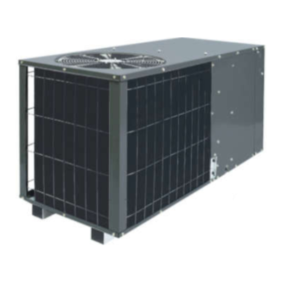
*PH 16 PACKAGE HEAT PUMPS
*PC 15 PACKAGE COOLING
HORIZONTAL MODELS
WITH R-410A
This manual is to be used by qualified, professionally trained HVAC technicians only.
RS6334002r1
Goodman does not assume any responsibility for property damage or personal injury
November 2015
due to improper service procedures or services performed by an unqualified person.
© 2015 Goodman Manufacturing Company, L.P.
1
Advertisement
Table of Contents

Related Manuals for Goodman *PH 16


Summary of Contents for Goodman *PH 16
-
Page 1: Service Instructions
This manual is to be used by qualified, professionally trained HVAC technicians only. RS6334002r1 Goodman does not assume any responsibility for property damage or personal injury November 2015 due to improper service procedures or services performed by an unqualified person. -
Page 2: Table Of Contents
INDEX IMPORTANT INFORMATION ......................4 - 5 PRODUCT IDENTIFICATION - *PC15/*PH16**H41** ............... 6 PRODUCT DIMENSIONS ........................7 ACCESSORIES ........................... 8 PCCP101-103 ROOF CURB ............................9 PCP101-103 DOWNFLOW PLENUM ..........................9 PCEF101-103 ELBOW AND FLASHING KIT ....................... 10 PCE101-103 ECONOMIZER ............................10 PCMD101-103 DOWNFLOW MANUAL DAMPER ...................... - Page 3 INDEX S-17D Operation Test ..............................30 S-18 TESTING CRANKCASE HEATER ........................31 S-18A CHECKING CRANKCASE HEATER THERMOSTAT ................... 31 S-21 CHECKING REVERSING VALVE AND SOLENOID ....................31 S-24 TESTING DEFROST CONTROL .......................... 31 S-25 TESTING DEFROST THERMOSTAT ........................31 S-50 CHECKING HEATER LIMIT CONTROL(S) ......................32 S-52 CHECKING HEATER ELEMENTS ........................
-
Page 4: Important Information
To locate an authorized servicer, please consult your telephone book or the dealer from whom you purchased this product. For further assistance, please contact: ® AMANA BRAND PRODUCTS ® GOODMAN BRAND PRODUCTS TOLL FREE TOLL FREE 1-877-254-4729 (U.S. only) 1-877-254-4729 (U.S. only) email us at: customerservice@goodmanmfg.com... -
Page 5: Important Information
IMPORTANT INFORMATION SAFE REFRIGERANT HANDLING While these items will not cover every conceivable situation, they should serve as a useful guide. WARNING WARNING O AVOID POSSIBLE EXPLOSION: EFRIGERANTS ARE HEAVIER THAN AIR. HEY CAN "PUSH OUT" THE • EVER APPLY FLAME OR STEAM TO A REFRIGERANT CYLINDER. F YOU OXYGEN IN YOUR LUNGS OR IN ANY ENCLOSED SPACE. -
Page 6: Product Identification - *Pc15/*Ph16**H41
The model number is used for positive identification of component parts used in manufacturing. Please use this number when requesting service or parts information. G / A BRAND: MINOR ® G: Goodman REVISION: Brand or CONFIGURATION: ® Distinctions H: Horizontal ®... -
Page 7: Product Dimensions
PRODUCT DIMENSIONS BACK (DUCT OPENINGS) Chassis Model Chassis Model *PH162441** 22.000 29.932 *PC1524 Small *PH163041** 22.000 29.932 *PC1530 Small *PH163641** 24.000 34.932 *PC1536 *PC1542 Medium *PH164241** 24.000 34.932 *PC1548 *PH164841** 24.000 34.932 Medium *PC1560 Dimensions in inches Dimensions in inches... -
Page 8: Accessories
Flush Mount Concentric Duct Kit CDK4872515 Flush Mount Concentric Duct Kit w/ Filter CDK4872530 Step Down Concentric Duct Kit CDK4872535 Step Down Concentric Duct Kit w/ Filter ® GOODMAN BRAND THERMOSTATS CH70TG Manual Changeover Digital, Nonprogrammable 1 Heat - 1 Cool CHSATG Manual Changeover... -
Page 9: Pccp101-103 Roof Curb
*PC15/*PH16H41* ACCESSORIES PCCP101-103 ROOF CURB 64" 59" 29 3/8" 29 3/4" 33" 33" Roof 14" Curb 31" 26" PCP101-103 DOWNFLOW PLENUM (Use with PCCP Roof Curb) 1" Flange 28 3/4" 25 1/2" 33" 13" 13" 37"... -
Page 10: Pcef101-103 Elbow And Flashing Kit
*PC15/*PH14641* ACCESSORIES PCEF101-103 ELBOW AND FLASHING KIT 28" 35" 25" 33" 3" 4" 4" 8" 25" PCE*101-103 ECONOMIZER* (DOWNFLOW APPLICATIONS) 5" 20 3/8" 16 1/2" 17 3/4" 27 3/4" 31 1/4" 17 3/4" Model Used With 3" PCEC101-103* *PC HORIZONTAL A/C 20"... -
Page 11: Pcmd101-103 Downflow Manual Damper
*PC15/*PH16H41* ACCESSORIES PCMD101-103 DOWNFLOW MANUAL DAMPER* PCMDM101-103 DOWNFLOW MOTORIZED DAMPER* *USED WITH PCP101-103 DOWNFLOW PLENUM 10" 6" 18" 29 3/4" MODEL DESCRIPTION PCMDH101-103 Manual Damper PCMDM101-103 Motorzied Damper GPHMD101-103 HORIZONTAL MANUAL DAMPER WITH DUCT FLANGE 18" 12" 6" 2" 17"... -
Page 12: Sqrpc Square To Round Converter
*PC15/*PH16H41* ACCESSORIES SQRPC SQUARE TO ROUND CONVERTER (DOWNFLOW APPLICATIONS) 1" FLANGES 1 1/2" 29 1/4" 29 1/2" SQRPC101 SQRP102-103 16" 18" 16" 18" SQRPCH SQUARE TO ROUND CONVERTER (HORIZONTAL APPLICATIONS) SQUARE TO ROUND DUCT CONVERTER PANEL OUTER FLANGE BEAD 2" RETURN SUPPLY 2"... -
Page 13: Pcfr101-103 External Filter Kit
*PC15/*PH16H41* ACCESSORIES PCFR101-103 EXTERNAL FILTER KIT (HORIZONTAL APPLICATIONS) 14" x 25" x 2" FILTER... -
Page 14: Product Design
PRODUCT DESIGN LOCATION & CLEARANCES NOTE: To ensure proper condensate drainage, unit must be in- stalled in a level position. In installations where the unit is installed above ground level and not serviceable from the ground (Example: Roof Top installations) the installer must provide a service platform for the service person with rails or guards in accordance with local codes or ordinances. -
Page 15: Electrical Wiring
PRODUCT DESIGN Air for condensing (cooling) is drawn through the outdoor coil INDOOR BLOWER MOTOR by a propeller fan, and is discharged vertically out the top of All *PC15/*PH16 model package units use a EEM blower mo- the unit. The outdoor coil is designed for .0 static. No addi- tor. -
Page 16: Line Voltage Wiring
PRODUCT DESIGN TWO SPEED APPLICATION (APH1648 / APC1560) Run the unit on low stage cooling for 10 minutes until WARNING refrigerant pressures stabilize. Follow the guidelines and methods below to check unit operation and ensure that DO NOT EXCEED THE MAXIMUM OVERCURRENT the refrigerant charge is within limits. - Page 17 PRODUCT DESIGN SATURATED SATURATED SUCTION PRESSURE LIQUID PRESSURE GPC15 TEMPERATURE CHART TEMPERATURE CHART SATURATED SATURATED Design Superheat @ 95°F Outdoor Ambient SUCTION SUCTION LIQUID LIQUID Temperature PRESSURE TEMPERATURE PRESSURE TEMPERATURE Superheat ºF ºF Model # Supercooling ±2°F PSIG R-410A PSIG R-410A ±2°F GPC1524H41...
-
Page 18: System Operation
SYSTEM OPERATION SYSTEM OPERATION *PC15/*PH16**H41* COOLING When the contacts of the room thermostat close, this closes the circuit from R to Y and R to G in the unit. The refrigerant used in the system is R-410A. It is a clear, colorless, non-toxic and non-irritating liquid. -
Page 19: Defrost Cycle
*PC15/*PH16**H41* SYSTEM OPERATION *PH MODELS EQUIPPED WITH EEM BLOWER MO- calls for heat. At the end of the timing period, the unit’s TORS defrost cycle will be initiated provided the sensor remains closed. When the sensor opens (approximately 60° F), the With the thermostat set to the emergency heat position, R to defrost cycle is terminated and the timing period is reset. - Page 20 SYSTEM OPERATION TYPICAL PACKAGE COOLING Indoor Outdoor Coil Coil Chatleff Orifice Assy RESTRICTOR ORIFICE ASSEMBLY IN COOLING OPERATION In the cooling mode the orifice is pushed into its seat forcing refrigerant to flow through the metered hole in the center of the orifice.
- Page 21 SYSTEM OPERATION TYPICAL HEAT PUMP SYSTEM IN COOLING Reversing Valve (Energized) Indoor Outdoor Coil Coil Accumulator TYPICAL HEAT PUMP SYSTEM IN HEATING Reversing Valve (De-Energized) Indoor Outdoor Coil Coil Accumulator...
-
Page 22: Scheduled Maintenance
SCHEDULED MAINTENANCE The owner should be made aware of the fact, that, as with any 6. Check the contacts of the compressor contactor. If they mechanical equipment the Package Cooling and Heat Pump are burned or pitted, replace the contactor. units require regularly scheduled maintenance to preserve high 7. -
Page 23: Servicing
SERVICING SERVICING COOLING /HEAT PUMP- SERVICE ANALYSIS GUIDE Sys te m Unsatis factory Com plaint No Cooling Ope rating Cooling/He ating Pre s s ure s POSSIBLE CAUSE Test Method DOTS IN ANALYSIS Remedy GUIDE INDICATE "POSSIBLE CAUSE" • Pow er Failure Test V oltage •... -
Page 24: Checking Voltage
SERVICING S-2 CHECKING WIRING S-1 CHECKING VOLTAGE WARNING WARNING 1. Check wiring visually for signs of overheating, damaged 1. Remove doors, control panel cover, etc. from unit being insulation and loose connections. tested. 2. Use an ohmmeter to check continuity of any suspected With power ON: open wires. -
Page 25: S-3B Cooling Anticipator
SERVICING 3. Set fan selector switch at thermostat to "ON" position. WARNING 4. With voltmeter, check for 24 volts at wires C and G. 5. No voltage, indicates the trouble is in the thermostat or wiring. 6. Check the continuity of the thermostat and wiring. Repair or replace as necessary. -
Page 26: Checking Contactor Contacts
SERVICING S-12 CHECKING HIGH PRESSURE CONTROL S-8 CHECKING CONTACTOR CONTACTS WARNING HIGH VOLTAGE! Disconnect ALL power before servicing DISCONNECT POWER SUPPLY BEFORE SERVICING. or installing this unit. Multiple power sources may be present. Failure to do so may cause property damage, personal injury SINGLE PHASE or death. -
Page 27: S-15A Resistance Check
SERVICING S-15A RESISTANCE CHECK CAPACITOR, START SCROLL COMPRESSOR MODELS Hard start components are not required on Scroll compressor WARNING equipped units due to a non-replaceable check valve located in the discharge line of the compressor. However hard start kits are available and may improve low voltage starting characteris- tics. -
Page 28: S-15B Capacitance Check
SERVICING S-15B CAPACITANCE CHECK WARNING WARNING DISCHARGE CAPACITOR THROUGH A 20 TO 30 OHM RESISTOR BEFORE HANDLING. Using a hookup as shown below, take the amperage and volt- age readings and use them in the formula: 1. Remove the motor leads from its respective connection points and capacitor (if applicable). -
Page 29: Checking Compressor Windings
SERVICING Therefore, proper evacuation of a hermetic system is essen- High Voltage tial at the time of manufacture and during servicing. To reduce the possibility of external ignition, all open flame, Connections electrical power, and other heat sources should be extinguished 3/16"... -
Page 30: S-17B Ground Test
SERVICING S-17B GROUND TEST S-17D OPERATION TEST If fuse, circuit breaker, ground fault protective device, etc., has If the voltage, capacitor, overload and motor winding test fail to tripped, this is a strong indication that an electrical problem show the cause for failure: exists and must be found and corrected. -
Page 31: Testing Crankcase Heater
SERVICING If the valve fails to change its position, test the voltage (24V) at S-18 TESTING CRANKCASE HEATER the valve coil terminals, while the system is on the COOLING (OPTIONAL ITEM) cycle. Note: Not all compressors use crankcase heaters. If no voltage is registered at the coil terminals, check the op- eration of the thermostat and the continuity of the connecting The crankcase heater must be energized a minimum of twenty- wiring from the "O"... -
Page 32: Checking Heater Limit Control(S)
SERVICING S-100 REFRIGERATION REPAIR PRACTICE S-25 TESTING DEFROST THERMOSTAT 1. Install a thermocouple type temperature test lead on the tube adjacent to the defrost control. Insulate the lead point DANGER of contact. 2. Check the temperature at which the control closes its con- ALWAYS REMOVE THE REFRIGERANT CHARGE IN tacts by lowering the temperature of the control. -
Page 33: S-101 Leak Testing
SERVICING S-101 LEAK TESTING This is the most important part of the entire service procedure. The life and efficiency of the equipment is dependent upon the (NITROGEN OR NITROGEN-TRACED) thoroughness exercised by the serviceman when evacuating air (non-condensable) and moisture from the system. WARNING Air in a system causes high condensing temperature and pres- sure, resulting in increased power input and reduced perfor-... -
Page 34: S-103 Charging
SERVICING gauge. See that the vacuum pump will blank-off to a maxi- For charging in the warmer months, 10 F superheat at the com- mum of 25 microns. A high vacuum pump can only pro- pressor is required at conditions: 95 F outdoor ambient (dry bulb temperature), 80 F dry bulb / 67... -
Page 35: S-104 Checking Compressor Efficiency
SERVICING NOTE: Even though the compressor section of a Scroll com- pressor is more tolerant of liquid refrigerant, continued flood- CAUTION back or flooded start conditions may wash oil from the bearing To prevent personal injury, carefully connect and surfaces causing premature bearing failure. S-104 CHECK- disconnect manifold gauge hoses. -
Page 36: S-111 Fixed Orifice Restriction Devices
SERVICING CHECKING EQUALIZATION TIME 2. Install a high side pressure gauge on the liquid access fitting. During the "OFF" cycle, the high side pressure bleeds to the low side through the fixed orifice restriction device. Check 3. Record the gauge pressure and the temperature of the line. equalization time as follows: 4. -
Page 37: S-114 Non-Condensables
NOTE: GOODMAN DOES NOT APPROVE THE FLUSHING The use of a wet rag sometimes can be a nuisance. There are METHOD USING R-11 REFRIGERANT. - Page 38 SERVICING Pressure vs. Temperature Chart R-410A PSIG °F PSIG °F PSIG °F PSIG °F PSIG °F PSIG °F -37.7 114.0 37.8 216.0 74.3 318.0 100.2 420.0 120.7 522.0 137.6 -34.7 38.7 74.9 100.7 121.0 137.9 116.0 218.0 320.0 422.0 524.0 -32.0 118.0 39.5...
- Page 39 SERVICING REQUIRED LIQUID LINE TEMPERATURE LIQUID PRESSURE LIQUID PRESSURE REQUIRED SUBCOOLING TEMPERATURE (°F) AT ACCESS FITTING (PSIG) AT SERVICE VALVE (PSIG)
-
Page 40: S-125 Thermostatic Expansion Valve
SERVICING S-200 CHECKING EXTERNAL STATIC S-125 THERMOSTATIC EXPANSION VALVE PRESSURE The expansion valve is designed to control the rateof liquid The minimum and maximum allowable duct static pressure is refrigerant flow into an evaporator coil in exact proportion to the found in the Technical Information Manual. -
Page 41: S-201 Checking Temperature Rise
SERVICING S-201 CHECKING TEMPERATURE RISE Temperature rise is related to the BTUH output of the unit and the amount of air (CFM) circulated over the indoor coil. All units are designed for a given range of temperature increase. This is the temperature of the air leaving the unit minus the temperature of the air entering the unit. -
Page 42: Airflow
AIRFLOW ADJUSTING SPEED TAP FOR INDOOR BLOWER MOTOR Evaporator Blower Specifications with ECM Motors APH1624H41 / APC1524H41 APH1630H41 / APC1530H41 Cooling/HP Adjust Electric Adjust Cooling/HP Adjust Electric Adjust CFM* CFM* CFM* CFM* Speed Heat Speed Heat Minus Minus Minus Minus Normal Normal Normal... - Page 43 AIRFLOW SPEED SWITCH SWITCH COOLING/HP SPEED SWITCH SWITCH ELECTRIC MODEL MODEL HEAT (CFM) APC1524 APC1524 APH1624 APH1624 APC1530 APC1530 APH1630 1034 APH1630 1034 1,073 1,073 APC1536 1067 APC1536 1067 APH1636 1179 APH1636 1179 1273 1273 1222 1222 1298 1298 APC1542 APC1542 APH1642 1327...
-
Page 44: Wiring Diagrams
GPC15[24-48]H41** WIRING DIAGRAMS NOTE #3 SEE NOTE 5 LVJB RCCF (IF USED) SEE NOTE 4 CONTROL C L G N 1 2 3 COMP SEE NOTE 2 COMPONENT LEGEND FACTORY WIRING LINE VOLTAGE BLOWER INTERLOCK RELAY LOW VOLTAGE SUPPLY VOLTAGE OPTIONAL HIGH CONTACTOR 208-240/1/60... -
Page 45: Gpc1560H41
GPC1560H41** WIRING DIAGRAMS NOTE #3 NOTE 5 LVJB RCCF (IF USED) SEE NOTE 4 CONTROL C L G N 1 2 3 COMP SEE NOTE 2 COMPONENT LEGEND FACTORY WIRING LINE VOLTAGE LOW VOLTAGE CONTACTOR SUPPLY VOLTAGE OPTIONAL HIGH 208-230/1/60 VOLTAGE CONDENSER MOTOR COMP... -
Page 46: Apc15[24-48]H41
APC15[24-48]H41** WIRING DIAGRAMS NOTE #2 SEE NOTE 4 LVJB RCCF (IF USED) SEE NOTE 3 CONTROL COMP COMPONENT LEGEND FACTORY WIRING LINE VOLTAGE LOW VOLTAGE BLOWER INTERLOCK RELAY SUPPLY VOLTAGE OPTIONAL HIGH CONTACTOR 208-230/1/60 VOLTAGE CRACKCASE HEATER CONDENSER MOTOR FIELD WIRING COMP COMPRESSOR HIGH VOLTAGE... -
Page 47: Apc1560H41
APC1560H41** WIRING DIAGRAMS NOTE #2 NOTE 4 LVJB RCCF (IF USED) SEE NOTE 3 CONTROL COMP COMPONENT LEGEND FACTORY WIRING LINE VOLTAGE LOW VOLTAGE SUPPLY VOLTAGE OPTIONAL HIGH CONTACTOR 208-230/1/60 VOLTAGE CONDENSER MOTOR FIELD WIRING COMP COMPRESSOR HIGH VOLTAGE LOW VOLTAGE EVAPORATOR MOTOR COMP WIRE CODE... -
Page 48: Gph16[24-42]H41
GPH16[24-42]H41** WIRING DIAGRAMS SEE NOTE 8 SEE NOTE 3 SEE NOTE 7 YL/PK SEE NOTE 5 LVDR 0-RV LVJB C-RV HVDR RCCF SEE NOTE 4 SEE NOTE 6 CONTROL L G N COMP SEE NOTE 2 SEE NOTE 6 FACTORY WIRING COMPONENT LEGEND LINE VOLTAGE CONTACTOR... -
Page 49: Gph1648H41
GPH1648H41** WIRING DIAGRAMS NOTE 8 SEE NOTE 3 NOTE 7 YL/PK SEE NOTE 5 LVDR 0-RV LVJB C-RV HVDR RCCF SEE NOTE 4 SEE NOTE 6 CONTROL L G N COMP SEE NOTE 2 SEE NOTE 6 FACTORY WIRING COMPONENT LEGEND LINE VOLTAGE CONTACTOR COMPRESSOR CONTACTOR RELAY... -
Page 50: Aph16[24-42]H41
APH16[24-42]H41** WIRING DIAGRAMS SEE NOTE 9 SEE NOTE 2 SEE NOTE 8 SEE NOTE 4 YL/PK LVDR NOTES 0-RV 5 & 6 C-RV LVJB HVDR RCCF Y1/Y2 SEE NOTE 3 NOTE 7 CONTROL BL/PK COMP 16 PIN PLUG COMPONENT LEGEND FACTORY WIRING CONTACTOR SUPPLY VOLTAGE... -
Page 51: Aph1648H41
APH1648H41** WIRING DIAGRAMS 3 CSR SEE NOTE 9 SEE NOTE 2 SEE NOTE 8 SEE NOTE 4 YL/PK YL/PK LVDR NOTES 0-RV 5 & 6 C-RV LVJB HVDR RCCF SEE NOTE 3 NOTE 7 CONTROL NOTE 7 BL/PK BL/PK COMP 16 PIN PLUG FACTORY WIRING... -
Page 52: Ot18-60A Outdoor Thermostat
WIRING DIAGRAMS PACKAGE SYSTEM WIRING DIAGRAM - 1 STAGE ELECTRIC HEAT TYPICAL HP ROOM THERMOSTAT SEE NOTE 1 #18 GAUGE 7 WIRE PACKAGE UNIT REQUIRED FOR LOW VOLTAGE HEAT PUMPS JUNCTION BOX YELLOW GREEN ORANGE WHITE BLUE OUTDOOR THERMOSTAT CLOSE ON TEMPERATURE FALL PACKAGE SYSTEM WIRING DIAGRAM - 2 STAGE ELECTRIC HEAT ABOVE 10 KW TYPICAL HP... -
Page 53: Ot18-60A Outdoor Thermostat
WIRING DIAGRAMS PACKAGE SYSTEM WIRING DIAGRAM - HEAT PUMPS ONLY! TWO-STAGE ELECTRIC HEAT ABOVE 10 kW TYPICAL H/P ROOM THERMOSTAT #18 GAUGE 8 WIRE PACKAGE HEAT PUMP YELLOW GREEN OUTDOOR THERMOSTAT #2 (IF USED, SEE NOTE 1) ORANGE WHITE BROWN BLUE OUTDOOR THERMOSTAT #1 LOW VOLTAGE... -
Page 54: Single Phase Hkr/P** Heat Kits
*PC15/*PH16H41* WIRING DIAGRAMS HTR2 HTR1 HTR1 TL L1 L2 ONE (1) ELEMENT ROWS TWO (2) ELEMENT ROWS 5 KW 10 KW HTR1 HTR1 TL HTR2 HTR2 HTR3 HTR3 TL HTR4 L2 L1 L2 THREE (3) ELEMENT ROWS FOUR (4) ELEMENT ROWS L1 L2 20 KW 15 KW... -
Page 55: Pce* Economizer
*PC15/*PH16H41* WIRING DIAGRAMS PCE* ECONOMIZER FOR *PC/*PH****H41* Wiring is subject to change. Always refer to the wiring diagram on the unit for the most up-to-date wiring. -
Page 56: Spk* - Single Point Wiring Kit
WIRING DIAGRAMS SPK* - SINGLE POINT WIRING KIT Wiring is subject to change. Always refer to the wiring diagram on the unit for the most up-to-date wiring.
Need help?
Do you have a question about the *PH 16 and is the answer not in the manual?
Questions and answers