Advertisement
TECHNICAL INFORMATION MANUAL
GSH 14 SEER
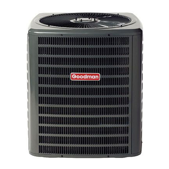
Remote Heat Pump
•
Refer to Service Manual RS6100004 for installation, op-
eration, and troubleshooting information.
•
All safety information must be followed as provided in the
Service Manual.
®
This manual is to be used by qualified HVAC technicians only. Goodman
does not assume any responsibility for property damage or personal injury
due to improper service procedures performed by an unqualified person.
Copyright © 2006 Goodman Manufacturing Company, L.P.
Models listed on page 3.
RT6213004
April 2006
Advertisement
Table of Contents

Summary of Contents for Goodman GSC140481A
- Page 1 TECHNICAL INFORMATION MANUAL GSH 14 SEER Remote Heat Pump • Refer to Service Manual RS6100004 for installation, op- eration, and troubleshooting information. • All safety information must be followed as provided in the Service Manual. ® This manual is to be used by qualified HVAC technicians only. Goodman does not assume any responsibility for property damage or personal injury due to improper service procedures performed by an unqualified person.
-
Page 2: Product Identification
(Standard Feature Set Models) S: Goodman Deluxe (High Feature Set Models) Product Family S: Split System Product Type C: Condenser R-22 X: Condenser R-410A H: Heat Pump R-22 Z: Heat Pump R-410A SEER SEER Rating WARNING WARNING WARNING WARNING GROUND MAY RESULT IN PRODUCT DAMAGE, PERSONAL INJURY OR DEATH. - Page 3 PRODUCT IDENTIFICATION The model number is used for positive identification of component parts used in manufacturing. Please use this number when requesting service or parts information. * Indicates minor revision & is not used for order entry or inventory management WARNING WARNING WARNING...
-
Page 4: Product Design
PRODUCT DESIGN GSH14 SEER split system heat pump models are available in 1 1/2 through 5 ton sizes. They are designed for 208/230 volt single phase applications. Air is drawn through the outdoor coil by a propeller fan, and is discharged vertically out the top of the unit. - Page 5 HEAT PUMP SPECIFICATIONS Cooling Capacity, BTUH 18,000 Compressor R.L. Amps L.R. Amps 41.0 Loss of Charge Pressure Switch Open / Close 7 PSIG/25 PSIG 7 PSIG/25 PSIG 7 PSIG/25 PSIG 7 PSIG/25 PSIG 7PSIG/25 PSIG 7 PSIG/25 PSIG 7PSIG/25 PSIG...
- Page 6 COOLING PERFORMANCE DATA GSH140181A*...
- Page 7 COOLING PERFORMANCE DATA GSH140181A*...
- Page 8 COOLING PERFORMANCE DATA GSH140241A*...
- Page 9 COOLING PERFORMANCE DATA GSH140241A*...
- Page 10 COOLING PERFORMANCE DATA GSH140301A*...
- Page 11 COOLING PERFORMANCE DATA GSH140301A*...
- Page 12 COOLING PERFORMANCE DATA GSH140361A*...
- Page 13 COOLING PERFORMANCE DATA GSH140361A*...
- Page 14 COOLING PERFORMANCE DATA GSH140421A*...
- Page 15 COOLING PERFORMANCE DATA GSH140421A*...
- Page 16 COOLING PERFORMANCE DATA GSH140481A*...
- Page 17 COOLING PERFORMANCE DATA GSH140481A*...
- Page 18 COOLING PERFORMANCE DATA GSH140601A*...
- Page 19 COOLING PERFORMANCE DATA GSH140601A*...
-
Page 20: Performance Data
PERFORMANCE DATA MODEL: GHS140181A* / CA*F3131B6A*+TXV / MBR800**-1 Condition: 80°F IDB 67°F IWB @ 600 CFM Outdoor Total Sensible Temp. ° F. Btuh Btuh 75° 18,900 13,282 80° 18,675 13,290 85° 18,450 13,295 90° 18,225 13,344 95° 18,000 13,389 100° 17,550 13,301 105°... - Page 21 SPLIT SYSTEM HEATING PERFORMANCE MODEL: GSH140181A* / CA*F3131B6A*+TXV / MBR800**-1 22.6 21.4 20.2 18.8 Delta T 34.9 33.1 31.1 29.1 1.56 1.53 1.50 1.47 AMPS 4.23 4.09 3.93 3.75 14.5 14.0 13.4 12.8 HI PR LO PR Above information is for nominal CFM and 70 degree indoor dry bulb. MODEL: GSH140241A* / CA*F3636B6A*+TXV / MBR800**1 30.2 28.6...
- Page 22 SPLIT SYSTEM HEATING PERFORMANCE MODEL: GSH140421A* / CA*F4860D6A*+TXV / MBR2000**-1 49.8 47.1 44.4 41.5 Delta T 32.9 31.2 29.3 27.4 3.20 3.14 3.08 3.02 AMPS 16.1 14.4 13.1 11.9 4.56 4.39 4.21 4.02 15.6 15.0 14.4 13.7 HI PR LO PR Above information is for nominal CFM and 70 degree indoor dry bulb.
-
Page 23: Heating Specifications
HEATING SPECIFICATIONS Model: GHS140181A* / CA*F3131B6A*+TXV / MBR800**-1 Condition: 600 CFM Indoor Air @ 70°F DB Basic Unit without Outdoor Auxiliary Heat With KW of Auxiliary heat Ambient °F. capacity btuh c.o.p. 22.63 4.23 39.008 21.42 4.09 37.802 20.16 3.93 36.542 18.85 3.75... - Page 24 2. As indoor CFM decreases, a slight increase will occur in indoor temperature drop (Delta T). A slight decrease will occur in low and high side pressures and power. A properly operating unit should be within plus or minus 2 degrees of the subcooling value shown in the Heat Pump Specifications.
-
Page 25: Wiring Diagrams
WIRING DIAGRAMS GSH140[18-60]1A* TO AVOID POSSIBLE ELECTRICAL SHOCK, PERSONAL INJURY, WARNING OR DEATH, DISCONNECT THE POWER BEFORE SERVICING. ONLY CONTACTOR POLE DOUBLE ALTERNATE Wiring is subject to change, always refer to the wiring diagram on the unit for the most up-to-date wiring.


Need help?
Do you have a question about the GSC140481A and is the answer not in the manual?
Questions and answers