Vega VEGAVIB 62 Operating Instructions Manual
Contactless electronic
Hide thumbs
Also See for VEGAVIB 62:
- Operating instructions manual (40 pages) ,
- Safety instructions (12 pages) ,
- Operating instructions manual (36 pages)

Subscribe to Our Youtube Channel
Related Manuals for Vega VEGAVIB 62


Summary of Contents for Vega VEGAVIB 62
-
Page 1: Operating Instructions
Operating Instructions VEGAVIB 62 - transistor (NPN/PNP) Document ID: 29273 Vibration... -
Page 2: Table Of Contents
Disposal ....... . . 26 VEGAVIB 62 • - transistor (NPN/PNP) -
Page 3: Vegavib 62 • - Transistor (Npn/Pnp)
You can find them listed in chapter "Product description". Instructions manuals for accessories and replacement parts Tip: To ensure reliable setup and operation of your VEGAVIB 62, we offer accessories and replacement parts. The corresponding documenta- tions are: 31086 - External housing - VEGAVIB... -
Page 4: About This Document
This symbol indicates special instructions for Ex applications. List The dot set in front indicates a list with no implied sequence. à Action This arrow indicates a single action. Sequence Numbers set in front indicate successive steps in a procedure. VEGAVIB 62 • - transistor (NPN/PNP) -
Page 5: For Your Safety
During work on and with the device the required personal protective equipment must always be worn. 2.2 Appropriate use The VEGAVIB 62 is a sensor for level detection. You can find detailed information on the application range in chapter "Product description". -
Page 6: Safety Label On The Instrument
You can find the CE conformity declaration in the download area of www.vega.com. 2.7 SIL conformity VEGAVIB 62 meets the requirements of functional safety according to IEC 61508. Further information is available in the Safety Manual "VEGAVIB series 60". -
Page 7: Product Description
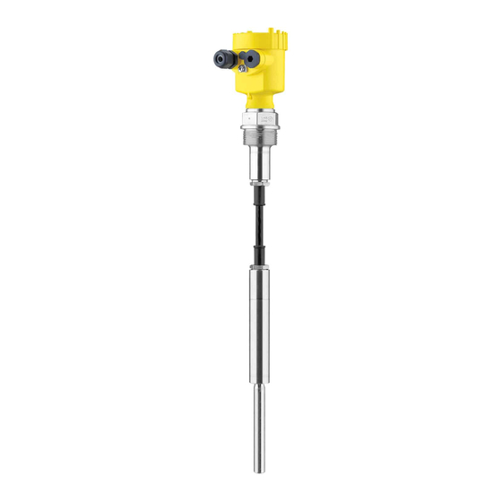
IEC 61511" (optional) Supplementary instructions manual "Plug connector for level sensors" (optional) Ex-specific "Safety instructions" (with Ex versions) if necessary, further certificates The VEGAVIB 62 consists of the following components: Constituent parts Housing cover Housing with electronics Process fitting with vibrating rod Fig. -
Page 8: Principle Of Operation
In addition to the type label outside, you can also find the serial number on the inside of the instrument. 3.2 Principle of operation VEGAVIB 62 is a point level sensor with vibrating rod for level Application area detection. -
Page 9: Operation
Not exposed to corrosive media Protected against solar radiation Avoiding mechanical shock and vibration Storage and transport Storage and transport temperature see chapter "Supplement - temperature Technical data - Ambient conditions" Relative humidity 20 … 85 % VEGAVIB 62 • - transistor (NPN/PNP) -
Page 10: Mounting
(e.g. through cleaning processes) or on cooled or heated vessels. Fig. 2: Measures against moisture penetration Do not hold VEGAVIB 62 on the vibrating element. Especially with Transport flange and tube versions, the sensor can be damaged by the weight of the instrument. -
Page 11: Mounting Instructions
filling and emptying apertures into account. To compensate measurement errors caused by the material cone in cylindrical vessels, the sensor must be mounted at a distance of d/6 from the vessel wall. VEGAVIB 62 • - transistor (NPN/PNP) - Page 12 4 Mounting Fig. 3: Filling and emptying centred VEGAVIB 62 • - transistor (NPN/PNP)
- Page 13 If VEGAVIB 62 is mounted in the filling stream, unwanted false Inflowing medium measurement signals can be generated. For this reason, mount VEGAVIB 62 at a position in the vessel where no disturbances, e.g. from filling openings, agitators, etc., can occur. VEGAVIB 62 • - transistor (NPN/PNP)
- Page 14 This baffle must be manufactured by you. > 125 mm ") Fig. 6: Baffle for protection against mechanical damage VEGAVIB 62 • - transistor (NPN/PNP)
-
Page 15: Connecting To Power Supply
Connect the operating voltage according to the following diagrams. Take note of the general installation regulations. As a rule, connect VEGAVIB 62 to vessel ground (PA), or in case of plastic vessels, to the next ground potential. On the side of the instrument housing there is a ground terminal between the cable entries. -
Page 16: Wiring Plan, Single Chamber Housing
10 If necessary, carry out a fresh adjustment 11 Screw the housing cover on The electrical connection is finished. 5.3 Wiring plan, single chamber housing The following illustrations apply to the non-Ex as well as to the EEx-d version. VEGAVIB 62 • - transistor (NPN/PNP) - Page 17 Filter element for pressure compensation or blind stopper with version IP 66/ IP 68, 1 bar (not with EEx d) We recommend connecting VEGAVIB 62 in such a way that the Wiring plan switching circuit is open when there is a level signal, line break or failure (safe condition).
-
Page 18: Wiring Plan - Version Ip 66/Ip 68, 1 Bar
Wire assignment con- nection cable Fig. 12: Wire assignment connection cable. The numbers of the wires correspond to the terminals of the instrument. brown (+) voltage supply White Yellow blue (-) voltage supply Shielding VEGAVIB 62 • - transistor (NPN/PNP) -
Page 19: Set Up
Note: As a rule, always set the mode with mode switch (2) before starting the setup of VEGAVIB 62. The switching output will change if you set the mode switch (2) afterwards. This could possibly trigger other connected instruments or devices. -
Page 20: Functional Chart
(1) is already preset and must only be modified in special cases. As a default setting, the potentiometer of VEGAVIB 62 is set to the complete right position (> 0.3 g/cm³/0.011 lbs/in³). In very light solids you have to turn the potentiometer to the complete left position (0.02 …... - Page 21 6 Set up Level Switching status Control lamp Mode min. open Dry run protection Failure of the sup- open ply voltage (min./max. mode) Failure open flashes red VEGAVIB 62 • - transistor (NPN/PNP)
-
Page 22: Maintenance And Fault Rectification
24 hour service hotline Should these measures not be successful, please call in urgent cases the VEGA service hotline under the phone no. +49 1805 858550. The hotline is available to you 7 days a week round-the-clock. Since we offer this service world-wide, the support is only available in the English language. -
Page 23: Exchanging The Electronics Module
Unscrew the housing cover Lift the opening levers of the terminals with a screwdriver Pull the connection cables out of the terminals Loosen the two screws with a screw driver (Torx size T10 or slot 4) VEGAVIB 62 • - transistor (NPN/PNP) -
Page 24: Instrument Repair
14 Check cable gland on tightness. The seal ring must completely encircle the cable. 15 Screw the housing cover on The electronics exchange is now finished. 7.4 Instrument repair If a repair is necessary, please proceed as follows: VEGAVIB 62 • - transistor (NPN/PNP) - Page 25 7 Maintenance and fault rectification You can download a return form (23 KB) from our Internet homepage www.vega.com under: "Downloads - Forms and certificates - Repair form". By doing this you help us carry out the repair quickly and without having to call back for needed information.
-
Page 26: Dismounting
Correct disposal avoids negative effects to persons and environment and ensures recycling of useful raw materials. Materials: see chapter "Technical data" If you have no way to dispose of the old instrument properly, please contact us concerning return and disposal. VEGAVIB 62 • - transistor (NPN/PNP) -
Page 27: Technical Data
(-40 … +150 °C/-40 … +302 °F) option- ally 3000 N (675 lbs) Max. permissible tensile load 0.48 … 80 m (1.575 … 262.47 ft) Sensor length (L) - suspension cable PUR (-20 … +80 °C/-4 … +176 °F) VEGAVIB 62 • - transistor (NPN/PNP) - Page 28 1.5 mm² (AWG 16) Spring-loaded terminals max. 20 mm (0.8 in) with product density < 0.05 g/cm³ (0.002 lbs/in³). Depending on the version M12 x 1, according to ISO 4400, Harting, 7/8" FF. VEGAVIB 62 • - transistor (NPN/PNP)
- Page 29 Aluminium and stainless housing (op- tionally available) Overvoltage category Protection class Approvals Depending on the version, instruments with approvals can have different technical data. A suitable cable is the prerequisite for maintaining the protection rating. VEGAVIB 62 • - transistor (NPN/PNP)
- Page 30 9 Supplement For these instruments, the corresponding approval documents have to be taken into account. These are part of the delivery or can be downloaded under www.vega.com via "VEGA Tools" and "serial number search" as well as via "Downloads" and "Approvals".
-
Page 31: Dimensions
~ 150mm (5 ") ø 77mm ø 84mm (3 ") ") M20x1,5 M20x1,5 M20x1,5 Fig. 26: Housing versions with protection rating IP 66/IP 68 (1 bar) Stainless steel housing - precision casting Aluminium housing VEGAVIB 62 • - transistor (NPN/PNP) - Page 32 ø 29 mm (1 ") ø 11 mm ( ") ø 29 mm (1 ") ø16 mm ( ") Fig. 27: VEGAVIB 62 - with PUR suspension cable Sensor length, see chapter "Technical data" VEGAVIB 62 • - transistor (NPN/PNP)
- Page 33 ø 29 mm (1 ") ø 10 mm ( ") ø 29 mm (1 ") ø16 mm ( ") Fig. 28: VEGAVIB 62 - with FEP suspension cable Sensor length, see chapter "Technical data" VEGAVIB 62 • - transistor (NPN/PNP)
-
Page 34: Information
Les lignes de produits VEGA sont globalement protégées par des droits de propriété intellectuelle. Pour plus d'informations, on pourra se référer au site http://www.vega. VEGA lineas de productos están protegidas por los derechos en el campo de la propiedad industrial. Para mayor información revise la pagina web http://www.vega.com Линии... - Page 35 9 Supplement VEGAVIB 62 • - transistor (NPN/PNP)
-
Page 36: Information
All statements concerning scope of delivery, application, practical use and operating conditions of the sensors and processing systems correspond to the information avail- able at the time of printing. © VEGA Grieshaber KG, Schiltach/Germany 2010 29273-EN-100805 Subject to change without prior notice...
Need help?
Do you have a question about the VEGAVIB 62 and is the answer not in the manual?
Questions and answers