Table of Contents
Advertisement
Quick Links
Advertisement
Table of Contents
Troubleshooting

Related Manuals for Rosemount FCL


Summary of Contents for Rosemount FCL
- Page 1 Instruction Manual LIQ-MAN-56, Rev B July 2017 FCL with 56 Transmitter...
- Page 2 ESSENTIAL INSTRUCTIONS WARNING READ THIS PAGE BEFORE PROCEEDING! RISK OF ELECTRICAL SHOCK Your purchase from Rosemount, Inc. has resulted in one of the finest instruments available for your Equipment protected throughout by double insulation. particular application. These instruments have been •...
- Page 3 If you have an FCL-01 (no pH sensor), enter the pH of the process liquid in the third control box. e. Move the cursor to NEXT and press ENTER/MENU. If you have an FCL-01, the display will change to show some basic keypad operation guidelines.
- Page 4 About This Document This manual contains instructions for installation and operation of the FCL-56 The following list provides notes concerning all revisions of this document. Rev. Level Date Notes 5/11 This is the initial release of the product manual. The manual has been reformatted to reflect the Emerson documentation style and updated to reflect any changes in the product offering.
-
Page 5: Table Of Contents
MODEL FCL–56 TABLE OF CONTENTS FCL-56 TABLE OF CONTENTS Section Title Page DESCRIPTION AND SPECIFICATIONS ..............Applications ......................Features ........................Specifications - General ................... Specifications - Sensor .................... Specifications - Transmitter ..................Ordering Information ....................INSTALLATION ....................... Unpacking and Inspection.................. - Page 6 LIST OF TABLES Number Title Page Ordering Information ....................Component Parts ..................... Accessories ......................Sensor Wiring ......................Display Abbreviations ....................10.1 Transmitter ........................10.2 Spare Parts....................... 10.3 Replacement Parts FCL-01 ..................10.4 Replacement Parts FCL-02 ..................Troubleshooting – Chlorine ..................11.5...
- Page 7 Menu Tree for pH Diagnostic Sub Menu ..............Menu Tree for Security Sub Menu................10-1 Chlorine Sensor Parts ....................10-2 Replacement Parts for the Flow Controller Assembly used in Model FCL-01..10-3 Replacement Parts for the Flow Controller Assembly used in Model FCL-02..11-1 Simulating Chlorine ....................
- Page 8 MODEL FCL– 56 This page left blank intentionally...
-
Page 9: Description And Specifications
9.5 and 10.0, consult the factory. the pH of the sample. The FCL is not intended for the The FCL is available in two options: Model FCL-01 determi- nation of total chlorine or combined with manual pH correction and Model FCL-02 with chlorine (like monochloramine). -
Page 10: Specifications - General
TPC (relays) are standard. Weight/shipping weight: Data logger: Data automatically stored every 30 seconds Model FCL-01: 10 lb/13 lb (4.5 kg/6.0 kg) for 30 days; older data removed to make room for Model FCL-02: 11 lb/14 lb (5.0 kg/6.5 kg) new data. -
Page 11: Ordering Information
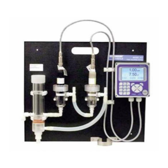
DESCRIPTION AND SPECIFICATIONS 1.6 ORDERING INFORMATION Model FCL Free Chlorine Measuring System. The FCL is a complete system for the determination of free chlo- rine in aqueous samples. It consists of the sensor(s), transmitter, and constant head overflow device to control sam- ple flow. - Page 12 MODEL FCL– 56 SECTION 1.0 DESCRIPTION AND SPECIFICATIONS This page left blank intentionally...
-
Page 13: Installation
Be sure all items shown on the packing list are present. If items are missing, notify Rosemount immediately. 2.1.1 MODEL FCL-01 (free chlorine without continuous pH correction) Model FCL-01 consists of the following items mounted on a back plate. Model 56-03-24-38-HT transmitter with sensor cable attached. -
Page 14: Installation
2.2.3 Mounting, Inlet, and Drain Connections The Model FCL is intended for wall mounting only. Refer to Figure 2-1 or 2-2 for details. The sensor(s) screw into the flow cell adapters as shown in the figures. For Model FCL-02 (free chlorine with continuous pH adjustment), the pH sensor must be installed as shown in Figure 2-2. - Page 15 MODEL FCL–56 SECTION 2.0 INSTALLATION...
-
Page 16: Model Fcl-01
MODEL FCL–56 SECTION 2.0 INSTALLATION INCH MILLIMETER FIGURE 2-1. Model FCL-01 INCH MILLIMETER FIGURE 2-2. Model FCL-02... - Page 17 MODEL FCL–56 SECTION 2.0 INSTALLATION This page left blank intentionally...
-
Page 18: Wiring
MODEL FCL– 56 SECTION 3.0 WIRING SECTION 3.0. WIRING 3.1 POWER, ALARM, AND OUTPUT WIRING WARNING RISK OF ELECTRICAL SHOCK Electrical installation must be in accordance with the National Electrical Code (ANSI/NFPA-70) and/or any other applicable national or local codes. -
Page 19: Sensor Wiring
3.2 SENSOR WIRING The Model FCL is provided with sensor cables pre-wired to the transmitter. If it is necessary to replace the sensor cable, refer to the instructions below. Shut off power to the transmitter. -
Page 20: Wiring Diagram For Free Chlorine Sensor
MODEL FCL– 56 SECTION 3.0 WIRING WHITE Figure 3-3. Wiring Diagram Figure 3-4. Wiring Diagram for Free Chlorine Sensor for 399VP-09 pH Sensor Figure 3-5. Wiring Diagram Figure 3-6. Wiring Diagram for 3900VP-10 pH sensor (gray cable) for 3900VP-10 pH sensor (blue cable) - Page 21 MODEL FCL– 56 This page left blank intentionally...
-
Page 22: Display And Operation
MODEL FCL– 56 SECTION 4.0 DISPLAY AND OPERATION SECTION 4.0 DISPLAY AND OPERATION 4.1. MAIN DISPLAY The transmitter has a four line display. See Figure 4-1. The display can be customized to meet user requirements. Section 4.5. Fault or warning messages, if appropriate, appear at the bottom of the screen. See Section 11.1. -
Page 23: Operation
MODEL FCL– 56 SECTION 4.0 DISPLAY AND OPERATION 4.3 OPERATION The operation of the Model 56 can best be understood from the following example. 1. With the main display showing (Figure 4-1), press the ENTER/MENU key. S1: 1.00 ppm 25.0qC S2: 7.00 pH 25.0qC... - Page 24 MODEL FCL– 56 SECTION 4.0 DISPLAY AND OPERATION The default dampening value is 0 seconds. To change the value, press S1: 1.00 ppm 25.0qC S2: 7.00 pH 25.0qC ENTER/MENU. The dark blue back-lighting will disappear indicating that Outputs Relays Measure Temperature Security a number can be entered.
-
Page 25: Hold
MODEL FCL– 56 SECTION 4.0 DISPLAY AND OPERATION 4.4 HOLD 4.4.1 Purpose To prevent unwanted alarms and improper operation of control systems or dosing pumps, place the alarm relays and outputs assigned to the sensor in hold before removing the sensor for maintenance. Hold is also useful if calibration, for example, buffering a pH sensor, will cause an out of limits condition. -
Page 26: Main Display
MODEL FCL– 56 SECTION 4.0 DISPLAY AND OPERATION 4.5 MAIN DISPLAY 4.5.1 Configuring the main display The main display can be configured to meet specific user requirement s. 1. With the main display showing, press ENTER/MENU. The main menu will S1: 1.00 ppm 25.0qC... -
Page 27: Security
MODEL FCL– 56 SECTION 4.0 DISPLAY AND OPERATION 4.6 SECURITY 4.6.1 How the Security Code Works Security codes prevent accidental or unwanted changes to program settings or calibrations. There are three levels of security. a. A user can view the main display and diagnostic screens only. -
Page 28: Programming The Transmitter
MODEL FCL– 56 SECTION 5.0 PROGRAMMING THE TRANSMITTER SECTION 5.0 PROGRAMMING THE TRANSMITTER 5.1 ENTERING THE PROGRAM MENUS 1. With the main display showing, press ENTER/MENU to display the main S1: 1.00 ppm 25.0qC S2: 7.00 pH 25.0qC menu. Move the cursor to Program and press ENTER/MENU. -
Page 29: Relays
MODEL FCL– 56 SECTION 5.0 PROGRAMMING THE TRANSMITTER 5.2.2. Settings Move the cursor to the appropriate control box and make the desired setting. For more information about the con- trol box the cursor is on press INFO. To close the information screen, press any key. - Page 30 Setpoint alarm info Delay timer info Interval timer info Date and time timer info The totalizer-based relay timer is not available in the FCL. It is available TPC info Totalizer based timer info only if one of the measurements is flow.
-
Page 31: Measurement
Dual slope calibration Solution temperature correction* Isopotential pH * For FCL-02, choose, Live/automatic. For FCL-01, choose manual and set manual pH to the expected pH * If the pH measurement is being made to correct the of the process liquid. -
Page 32: Ph Diagnostic Setup
MODEL FCL– 56 SECTION 5.0 PROGRAMMING THE TRANSMITTER 5.5.2. Settings Move the cursor to the appropriate control box and make the desired setting. For more information about the con- trol the cursor is on press INFO. To close the information screen, press any key. - Page 33 MODEL FCL– 56 This page left blank intentionally...
-
Page 34: Calibration
MODEL FCL– 56 SECTION 6.0 CALIBRATION SECTION 6.0 CALIBRATION 6.1 INTRODUCTION The calibrate menu allows the user to do the following: 1. Calibrate the RTD (temperature sensing element) in the chlorine and pH sensors. 2. Calibrate the chlorine sensor. 3. Calibrate the pH sensor. Four methods are available. -
Page 35: Calibrating The Free Chlorine Sensor
3. To calibrate the sensor response in chlorinated water, select Grab and follow the prompts. Be sure the sensor is installed in the flow cell in the FCL and the sample is overflowing the inside tube in the overflow sampler. If you are calibrating the FCL-02, calibrate the pH sensor first and install it in its flow cell before calibrating the free chlorine sensor. -
Page 36: Calibrating The Ph Sensor
MODEL FCL– 56 SECTION 6.0 CALIBRATION 6.5 CALIBRATING THE pH SENSOR 1. Choosing sensor 2 (pH) in section 6.2 causes the screen shown at left to S1: 1.00 ppm 25.0qC S2: 7.00 pH 25.0qC appear. There are five possible ways to calibrate the pH sensor. Select Why is calibration necessary? To find out press INFO. - Page 37 MODEL FCL– 56 This page left blank intentionally...
-
Page 38: Digital Communications
MODEL FCL– 56 SECTION 7.0 DIGITAL COMMUNICATIONS SECTION 7.0 DIGITAL COMMUNICATIONS The Model 56 transmitter supplied with the FCL has HART communications as a standard feature. For more information refer to the Model 56 HART Addendum Manual. - Page 39 MODEL FCL– 56 This page left blank intentionally...
-
Page 40: Data And Event Logging And Retrieval
MODEL FCL– 56 SECTION 8.0 DATA AND EVENT LOGGING AND RETRIEVAL SECTION 8.0 DATA AND EVENT LOGGING AND RETRIEVAL 8.1. OVERVIEW Data and event logging is a standard feature in the Model 56 transmitter. However, the feature must be enabled. - Page 41 MODEL FCL– 56 SECTION 8.0 DATA AND EVENT LOGGING AND RETRIEVAL...
-
Page 42: Downloading Data And Events
MODEL FCL– 56 SECTION 8.0 DATA AND EVENT LOGGING AND RETRIEVAL 8.3. DOWNLOADING DATA AND EVENTS To download data or events, move the cursor to the download tab and press ENTER/MENU. Unscrew the USB port cover in the lower right hand corner of the front panel and insert a USB flash drive in the port. Press the appropriate button to download data or events. -
Page 43: Graphical Display
MODEL FCL– 56 SECTION 9.0 GRAPHICAL DISPLAY SECTION 9.0 GRAPHICAL DISPLAY 9.1. OVERVIEW The Model 56 has a dual graphical display. Each graph can be configured to meet user requirements, although the time axis on both graphs must be the same. The time scale can be one hour, one day, seven days, or 30 days. - Page 44 MODEL FCL– 56 This page left blank intentionally...
-
Page 45: Maintenance
MAINTENANCE 10.1 TRANSMITTER The transmitter used with the FCL needs little routine maintenance. Clean the transmitter case and front panel by wiping with a clean soft cloth dampened with water ONLY. Do not use solvents, like alcohol, that might cause a buildup of static charge. -
Page 46: Chlorine Sensor
MODEL FCL– 56 SECTION 10.0 MAINTENANCE 10.2 CHLORINE SENSOR 10.2.1 General. When used in clean water, the chlorine sensor requires little maintenance. Generally, the sensor needs maintenance when the response becomes sluggish or noisy or when readings drift following calibration. For a sensor used in potable water, expect to clean the membrane every month and replace the membrane and electrolyte solution every three months. -
Page 47: Ph Sensor
30 minutes at room temperature. Rinse the sensor thoroughly with water and soak in pH 4 buffer for several hours. Recalibrate the sensor in buffers before returning it to service. 10.3.3 Other Maintenance The 3900VP-02-10 or the older 399VP-09 sensor supplied with the Model FCL-02 is disposable. It has no replaceable parts. -
Page 48: Constant Head Flow Controller
10.4.3 Other Maintenance Table 10-2 and Figure 10-2 show the replacement parts for the flow controller assembly used in Model FCL-01. Table 10-3 and Figure 10-3 show replacement parts for the flow controller assembly used in Model FCL-02. -
Page 49: Replacement Parts For The Flow Controller Assembly Used In Model Fcl-01
Elbow, ¼ in FNPT x ¼ in OD tubing 1 lb/0.5 kg 9350029 Check valve, ¼ in FNPT 1 lb/0.5 kg 33823-00 Outside tube for constant head device 1 lb/0.5 kg FIGURE 10-2. Replacement Parts for the Flow Controller Assembly used in Model FCL-01. -
Page 50: Replacement Parts For The Flow Controller Assembly Used In Model Fcl-02
Elbow, ¼ in FNPT x ¼ in OD tubing 1 lb/0.5 kg 9350029 Check valve, ¼ in FNPT 1 lb/0.5 kg 33823-00 Outside tube for constant head device 1 lb/0.5 kg FIGURE 10-3. Replacement Parts for the Flow Controller Assembly used in Model FCL-02. -
Page 51: Troubleshooting
MODEL FCL– 56 SECTION 11.0 TROUBLESHOOTING SECTION 11.0 TROUBLESHOOTING 11.1 OVERVIEW The transmitter continuously monitors itself and the sensor(s) for problems. When the transmitter identifies a problem, the word warning or fault appears intermittently at the bottom of the display. To read the fault or warning message and troubleshooting information, press INFO. -
Page 52: Troubleshooting Calibration Problems
MODEL FCL– 56 SECTION 11.0 TROUBLESHOOTING 11.4 TROUBLESHOOTING CALIBRATION PROBLEMS If a calibration attempt results in an error or a likely error, the transmitter will display the appropriate warning screen. For troubleshooting suggestions, press the INFO key. 11.5 OTHER TROUBLESHOOTING — CHLORINE Although calibration troubleshooting information is available in the transmitter by pressing the INFO key, troubleshooting information for process measurement problems is not. -
Page 53: Other Troubleshooting - Ph
MODEL FCL– 56 SECTION 11.0 TROUBLESHOOTING 11.5.3 Sensor does not respond to changes in chlorine level. 1. Is the grab sample test accurate? Is the grab sample representative of the sample flowing to the sensor? 2. Is sample flowing past the sensor? Be sure the liquid level in the constant head sampler is level with the central overflow tube and that excess sample is flowing down the tube. - Page 54 MODEL FCL– 56 SECTION 11.0 TROUBLESHOOTING 11.6.3 Calibration Was Successful, but Process pH Is Grossly Wrong and/or Noisy. Grossly wrong or noisy readings suggest a ground loop (measurement system connected to earth ground at more than one point), a floating system (no earth ground), or noise being brought into the transmitter by the sensor cable.
-
Page 55: Other Troubleshooting - General
MODEL FCL– 56 SECTION 11.0 TROUBLESHOOTING 11.7 OTHER TROUBLESHOOTING — GENERAL Problem See Section Current output is too low 11.7.1 Alarm relays do not operate properly 11.7.2 11.7.1 Current Output Is Too Low. Load resistance is too high. Maximum is 550Ω. -
Page 56: Simulating Inputs - Ph
MODEL FCL– 56 SECTION 11.0 TROUBLESHOOTING 11.9 SIMULATING INPUTS — pH 11.9.1 General This section describes how to simulate a pH input into the transmitter. To simulate a pH measurement, connect a standard millivolt source to the transmitter. If the transmitter is working properly, it will accurately measure the input voltage and convert it to pH. -
Page 57: Simulating Inputs Temperature
MODEL FCL– 56 SECTION 11.0 TROUBLESHOOTING 11.10 SIMULATING INPUTS — TEMPERATURE 11.10.1 General. The transmitter accepts a Pt100 RTD (for pH and chlorine sensors). The Pt100 RTD is in a three-wire configuration. See Figure 9-5. 11.10.2 Simulating temperature To simulate the temperature input, wire a decade box to the transmitter as shown in Figure 11-4. - Page 58 NOTES...
- Page 59 NOTES...
- Page 60 +971 4 88665465 The Emerson logo is a trademark and service mark of Emerson RFQ.RMTMEA@Emerson.com Electric Co. Rosemount and Rosemount logotype are trademarks of Emerson. All other marks are the property of their respective owners. © 2017 Emerson. All rights reserved.
Need help?
Do you have a question about the FCL and is the answer not in the manual?
Questions and answers