
Summary of Contents for ANK Audio Note Kits M3 Phono Board
- Page 1 Manual Version 1.2 - July 2007 Copyright © 2007 AudioNote Kits Page 1 www.AudioNoteKits.com audionotekits@rogers.com...
-
Page 2: Table Of Contents
Continuing Construction..............................18 Installing R3 and R5................................20 Adding the Tube Shield Grounds............................20 Installing the Capacitors..............................23 Section 2: Final Wiring................................28 Section 3: Testing the M3 Phono Board..........................29 Hook-Up and Voltage Checks ............................30 Appendix....................................31 Resistor Color Code Reference ............................32 Phono Board Schematic ..............................33 Resistors and Color Codes ..............................34... -
Page 3: Section1: M3 Phono Board Build
Section1: M3 Phono Board Build There are two versions of the M3 Phono Board available. The Standard Copper Track PCB board is considered to be the simplest board to build whereas the Hard-Wired version is usually the choice of the more experienced builder. -
Page 4: Preparation
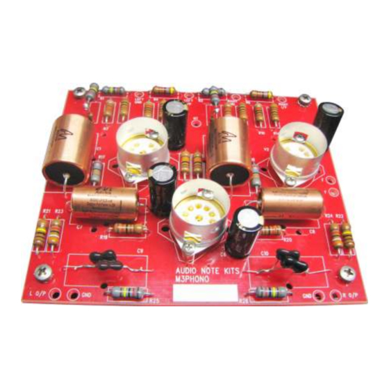
The above picture shows the top and bottom of the M3 Phono Board. The bottom of the board shows how the leg of each component is joined to another - these are shows by the thick white lines. - Page 5 Here are some tools that you will find very handy while working on the hardwired phono board – a cutter on the left, a wire stripper/cutter in the middle, and needle nose pliers on the right. Have your schematic and Resistor Color code chart handy! These will make it easier for you to verify that you have done the correct thing as you work through the various connections.
-
Page 6: Fitting The Valve Bases
Fitting the Valve Bases Our first installation will be the valve bases. As you can see from the picture opposite the valve base is inserted in the board and the small spacers are used under the screw holes. The Tube Shield is then used on top with the screws going through them. -
Page 7: Installing The Resistors
Installing the Resistors Our next task is to install MOST of the resistors in the board. Start by referring to your schematic and your Resistor Color Code Chart. You can start at the top of the chart. You will notice that the first resistor on the chart is the 820R resistor (R8 and R10). - Page 8 Above you can see the two resistors installed correctly into the board. You will also want to gently bend the leads on the underside of the board so that the resistors don’t fall out as we are going to install all the rest of the resistors (except for R3 &...
-
Page 9: Starting The Soldering
The next step is to gently bend down the resistor leads so that they are roughly following the traces. In some cases it will be straightforward; in others you will not be sure which way to go! Do your best! Some traces will require the needle nose pliers where you will have to bend the leads to follow the tracks! Starting the Soldering... - Page 10 I suggest using a highlighter to keep track of your successful connections so that you know where you are up to. So in our case we have just completed the wiring of pin 3 to pin 6 of the V1 (LEFT) Valve base – so highlight the connection with a highlighter or pen.
- Page 11 Lets start by looking for some easy connections of the resistors to the valve bases. For example, looking at the base on the upper right in the picture opposite, let's pick some easy connections that we can make – the connection to PIN 1 looks very easy – Bend the lead enough with the pliers to fit it into the valve base pin 1.
- Page 12 Once that wiring has been completed of R7 you will want to update your schematic as shown opposite. We just need to show you a few more techniques and then you will be well on your way to completing the resistor connections.
- Page 13 In this picture we have fed the silver wire through the valve base pin 2 and then applied some solder to the valve base pin. Then we have soldered to the resistor lead to complete the connection. Let's update our schematic with the new connection we have just made –...
- Page 14 We have completed all the connections to the valve base V1 – Note that I have not highlighted pin 7 yet but I should do that now! The only pins not connected now are pins 4 & 5 - these will be used for our filament wiring - in other words we will be using some wiring from the power supply board to connect to these pins to provide the filament current (this subject is...
- Page 15 If you look on the component side of the board you will see two circles with HT marked on them. Let's wire up the HT terminal for V1 – do this by using the silver wire to extend. You can see here that I am laying down a length of silver wire that I will be soldering to for the HT connection.
-
Page 16: Additional Techniques And Tips
Here I am soldering another lead to the silver wire that is the HT. At this point you should have enough skills to start working your way through the soldering process. Before proceeding, however, please read the following additional techniques. Additional Techniques and Tips Use your cutters to cut off excess wire after you have made a solder connection. - Page 17 This picture shows the next tricky part of the board - all the input resistors. These resistor legs need to be bent and pulled through the holes in the board Right I/P. RIGHT GND etc… Use your needle nose pliers to perform this task.
-
Page 18: Continuing Construction
USING INSULATION You will notice that in your kit you will have some thin heatshrink. You will use this in situations where the wires are coming close in contact with each other. When this is going to happen you need to cut some heatshrink to ensure that the wires will not short with one another! You will need to use a hair dryer, or heatshrink gun, to heat up the heatshrink so that it wraps –... - Page 19 If you look at the bottom left corner of the wiring side of the board you will see the spacer that is very close to the trace going to W8. You have two options – to use some heatshrink tubing and follow the trace or route the trace around the outside of the spacer as shown in this picture.
-
Page 20: Installing R3 And R5
Installing R3 and R5 R3 (left channel) and R5 (right channel) are a special case as each of them is actually made up of two resistors. The value of these resistors is 2M2 (or 2.2Meg ohms). Since this resistor value is not available in Tantalum, we are going to put a 1.2M (1M2 1W) resistor in series with a 1Meg 1/2W resistor. - Page 21 Use some of your silver wire to connect the GND lugs to the GND planes and solder. Be careful with this particular connection as is comes very close to a wire - you must make sure that there is some clearance.
- Page 22 At this stage all our resistors are installed and I have highlighted my schematic - see opposite. Copyright © 2007 AudioNote Kits Page 22 www.AudioNoteKits.com audionotekits@rogers.com...
-
Page 23: Installing The Capacitors
Installing the Capacitors First, we will install the 4 Electrolytic capacitors – these are all 470uf 16V and are used on the cathode of the tubes. These capacitors are polarized meaning that there is a + and a – (Negative) and its very important that they are put into position correctly –... - Page 24 Install C1, C2, C7, and C8. The picture opposite shows TIN capacitors installed in the C1 & C2 positions and copper caps installed in the C7 & C8 positions. Note that normally you will be using either all tin or all copper depending on what level Phono Kit you have ordered.
- Page 25 Now we come to the home stretch – We need to install the 4 Film capacitors that will be installed on the underside of the board. Now we come to the home stretch – We need to install the 4 Film capacitors that will be installed on the underside of the board –...
- Page 26 We will now install the 2x .33uf capacitors into C13 & C14. When installing these capacitors, the lines will be positioned closest to the center of the board. These capacitors will take a little more care – Solder the pin closest to the center of the board FIRST.
- Page 27 – Clip these about 5 mm from the top of the board and curl down. You will now have to do a similar operation on the other .33uf capacitor installed into C14. Congratulations – You have completed the M3 Phono Board. Copyright © 2007 AudioNote Kits Page 27 www.AudioNoteKits.com...
-
Page 28: Section 2: Final Wiring
Connect the HT from the power supply (B+) to the HT on the M3 Phono Board. Connect the GND from the power supply GND (near the LED) to one of the input GND’s on the M3 phono board. Copyright © 2007 AudioNote Kits Page 28 www.AudioNoteKits.com... -
Page 29: Section 3: Testing The M3 Phono Board
Section 3: Testing the M3 Phono Board If you have an OHM-meter you can use it at this stage to do some preliminary checks. From the top side of the board we are going to measure some resistances from the Tube sockets. -
Page 30: Hook-Up And Voltage Checks
If all the voltages check out then we can hook up the RCA’s and the AN-A or AN-V cable. Start by tinning the input and output wires on the M3 phono board – This is done by adding some solder to the hooked wires that are coming out the board at the Right I/P and Left I/P and R GND and L-GND.
Need help?
Do you have a question about the M3 Phono Board and is the answer not in the manual?
Questions and answers