
Subscribe to Our Youtube Channel
Related Manuals for YOKOGAWA SC150


Summary of Contents for YOKOGAWA SC150
- Page 1 Model SC150 Instruction Conductivity and Resistivity Manual Converter IM 12D7B4-E-H YOKOGAWA 2nd edition...
-
Page 3: Table Of Contents
3-5. Wiring the Power Supply ..................7 3-6. Wiring the Relay Contacts ..................7 3-7. Wiring the Current Output ..................8 3-8. Wiring the Sensors ....................9 4. OPERATION OF EXAxt SC150 ...................10 4-1. Main Display Functions ..................10 4-2. Trending Graphics....................10 4-3. Zoom in on Details .....................10 4-4. - Page 4 6. QUICK SETUP FOR THE EXAxt SC150..............30 7. CALIBRATION......................31 7-1. General ......................31 7-2. Cell Constant Manual ..................31 7-3. Cell Constant Automatic..................31 7-4. Air (Zero) Calibration...................31 7-5. Sample Calibration .....................31 7-6. Temperature Coefficient Calibration..............31 7-7. Temperature Calibration ..................32 7-8. General Comments on SC Calibration..............32 8.
-
Page 5: Preface
Do not use an abrasive or organic solvent in cleaning the instrument. Notice Contents of this manual are subject to change without notice. Yokogawa is not responsible for damage to the instrument, poor performance of the instrument or losses resulting from such, if the problems are caused by: Incorrect operation by the user. - Page 6 Part number, model code and serial number Original purchase order and date Length of time in service and a description of the process Description of the fault, and the circumstances of failure Process/environmental conditions that may be related to the failure of the device. A statement whether warranty or non-warranty service is requested Complete shipping and billing instructions for return of material, plus the name and phone number of a contact person who can be reached for further information.
-
Page 7: Introduction And General Description
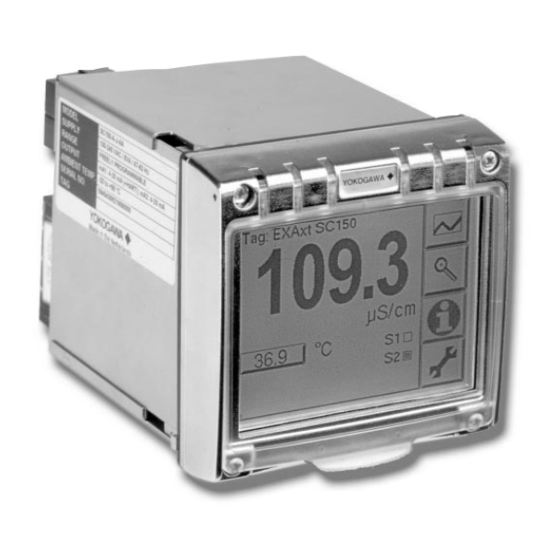
1. INTRODUCTION AND GENERAL DESCRIPTION The Yokogawa EXAxt SC150 is a 4-wire panel mounted converter designed for industrial process monitoring, measurement and control applications. This instruction manual contains the information needed to install, set up, operate and maintain the unit correctly. This manual also includes a basic troubleshooting guide to answer typical user questions. -
Page 8: Application
For best results, read this manual in conjunction with the corresponding sensor instruction manual. Yokogawa designed and built the EXAxt to meet the CE regulatory standards. The unit meets or exceeds stringent requirements (see section 2) without compromise, to assure the user of continued accurate performance in even the most demanding industrial installations. -
Page 9: General Specifications
2. General specifications of EXAxt SC150 I) Logbook : Software record of important A) Input specifications events and diagnostic data : Two or four electrodes readily available in the display. measurement with square wave J) Display : Graphical Quarter VGA (320 x... -
Page 10: Installation And Wiring
3. INSTALLATION AND WIRING 3-1. Installation site The EXAxt converter should be installed as close as possible to the sensor to avoid long cable runs between sensor and converter. In any case, the cable length should not exceed 60 meters (200 feet). Select an installation site where: Mechanical vibrations and shocks are negligible No relay/power switches are in the direct environment Access is possible rear of the unit for wiring... - Page 11 90 (3.54") Safety Cover 121 (4.75") 25 (1") 118 (4.6") 96 (3.8") Fig. 3-4. Housing dimensions and layout 100 (3.94") min Cut-Out 92x 92 Tol. +0,5/-0 (3.63" x 3.63" Tol. +0.02/-0) C / L Fig. 3-5. Panel mounting cut-out IM 12D7B4-E-H...
-
Page 12: Preparation
3-3. Preparation The power/output connections and the sensor connections should be made in accordance with the scheme shown in Figure 3-6. The terminals are of a plug in style for ease of wiring. 3-4. Cables, terminals and safety cover The EXAxt 150 is equipped with terminals suitable for the connection of finished cables in the size range: 0.13 to 2.5 mm (26 to 14 AWG). -
Page 13: Wiring The Power Supply
SENSOR CONTACT OUTPUT 9.6 to 30 VDC, 10W max POWER 85 to 265 VAC, 10VA max 4-20 mA OUTPUT SIGNALS INPUT CONTACT HAND HELD Figure 3-7. System configuration 3-5. Wiring the power supply Make sure the power supply is switched off. Also, make sure that the power supply is correct for the specifications of the EXAxt and that the supply agrees with the voltage specified on the textplate. -
Page 14: Wiring The Current Output
3-7. Wiring the Current Outputs The current outputs should be connected using twisted pair signal cable. The screen (shield) should be connected to ground (at one end only). Note: The HART signal is super imposed on mA 1. When using this signal, attention should be paid to the load resistance. -
Page 15: Wiring The Sensors
3-8. Wiring of sensors General precautions Generally, signals from sensors are at low voltage and current level. Thus a lot of care must be taken to avoid interference. Before connecting sensor cables to the transmitter make sure that following conditions are met: –... -
Page 16: Operation Of Exaxt Sc150
4-3. Zoom in on details 4. OPERATION OF EXAxt SC150 4-1. Main display functions This button gives access to the diagnostic Ma n Screen information of the analyzer. The following messages will appear under normal -Go to graph screen (default) conditions:... - Page 17 4-3-4. Temp. comp 2 = the chosen 4-3-10. Polarization perc. = the % temperature compensation method for the polarization measured by the input secondary measurement. circuitry. Monitoring this figure gives a guide to progressive fouling of the sensor. Note: This does not imply two separate measurements.
-
Page 18: Information Function
4-6. Setup-Calibration & Commissio- 4-4. Information function ning In this field an information sign , a warning By pressing the setup key, you get sign or a fail sign can appear. access to the operating system of the Pushing this button, the user gets detailed analyzer based on menus and submenus. -
Page 19: Matrix Interpolation
4-7. Matrix Interpolation Temperature compensation matrix. 1. A minimum number of values is required to make interpolation possible. The highlighted values markes as are mandatory to enter. Concent 2. T (reference temperature) is defined in the Temperature Compensation menu. If T between T an T then the value of T... - Page 20 IM 12D7B4-E-H...
-
Page 21: Menu Structure Commissioning
5. MENU STRUCTURE COMMISSIONING IM 12D7B4-E-H... -
Page 22: Configure Sensor
Measurement Setup 5-3. Temperature Compensation Main parameter Compensation Two types of methods can be used here. Choose the required parameter, either Automatic for use of temperature element. conductivity or resistivity. If the main Select one of the Temperature elements parameter is changed the instrument will reset main display settings, units and used. - Page 23 This selection will influence a number of choices and defaults throughout the whole menu. Generally defaults are shown with their ranges and possible choices. In the selection boxes defaults are shown with a black background. IM 12D7B4-E-H...
-
Page 24: Calibration Settings
5-4. Calibration Settings Calibration Interval Air adjust limit A user defined interval in which a new To avoid cable influences on the calibration should take place. If the interval measurement, a "zero" calibration with a is exceeded the instrument will give a dry sensor may be done. - Page 25 Generally defaults are shown with their ranges and possible choices. In the selection boxes defaults are shown with a black background. 21 data point table IM 12D7B4-E-H...
-
Page 26: Ma Output Setput
5-6. mA Output Setup General The general procedure is to define the function (control, output, Simulate, off) of the output and the process parameter connected to the output first. Available process parameters depend on selected sensor type and measurement setup. mA1/mA2 Off: : When an output is set off the... - Page 27 0.000 100.0 Note: default settings relate to conductivity, comparable defaults exist for resistivity IM 12D7B4-E-H...
-
Page 28: Contact Output Setput
5-7. Contact Output Setput S1/S2 Each Switch (contact) has 4 functions. Setpoint When a Switch is set to off the Switch is Hys. not used. Control: A selection of P- PI- or PID control Alarm: Low or high value Limits LED on LED off monitoring... - Page 29 alarm A Soft Fail enables the fail contact pulse A Soft Fail is shown on the display only Note: default settings relate to conductivity, comparable defaults exist for resistivity IM 12D7B4-E-H...
-
Page 30: Input Contact Setup
5-9. Input Contact Setup General Remote range switching to 10 times the programmed range. Factor 10 mA1 and/or mA2 This "ZOOM" function will cause the range of the mA to be multiplied by 10 when the binary input is closed. The range is divided by 10 when the binary contact is opened. - Page 31 Select functions: Note: The choices above only appear when linear conductivity is chosen on output 1 and/or 2. IM 12D7B4-E-H...
-
Page 32: Advanced Setup
5-12. Advanced setup Defaults The functionality of the EXAxt allows to save and load defaults to come to a known instrument setting. The EXAxt has both factory and user defined defaults. After a “load default” the instrument will reset. The following parameters are not included in a reset: X-axis timing Auto return (10 min / disabled) - Page 33 No action No action Load factory defaults After the defaults are loaded, Save current as user defined the instrument will reset Load user defined defaults IM 12D7B4-E-H...
-
Page 34: Display Setup
5-13. Display Setup Main Display The main display consists of three lines with Process Values. Each line is user definable with the restriction that each line should have a different Process Value. The default settings can be defined here. By pressing one of the two smaller process values, this will become the main process value in the main screen. - Page 35 Temperature Concentration Time Span (x) = 1 hour IM 12D7B4-E-H...
-
Page 36: Quick Setup For The Exaxt Sc150
6. QUICK SETUP FOR THE EXAxt SC150 G) S1 default is a High alarm with setpoint 500 µS/cm A) Check power supply voltage on the S2 default is Fail alarm as a fault instrument side label signal 9.6 -30 Volts... -
Page 37: Calibration
>> Configure sensor capacitance, and gives a better accuracy The Calibration menu of the SC150 is at low readings. This should be done for provided for fine tuning the sensor setup, all installations during commissioning. -
Page 38: Temperature Calibration
Sensor linearity is never a problem for lower values is allowed to stabilize at elevated temperature. EXAxt SC150 will calculate j) A dirty sensor is prone to polarization the temperature coefficient for you. The ideal temperature for this calibration, is the... -
Page 39: Maintenance
(Chapter 9) for replacement part numbers. NOTE: Resistance due to fouling or to polarization The nature of the EXAxt SC150 is that the does not effect the accuracy and operation panel environment should protect the back of a 4-electrode conductivity measuring of the instrument. -
Page 40: Troubleshooting
9-3. Polarization check 9. TROUBLESHOOTING The EXAxt SC150 performs on-line monitoring 9-1. General to detect polarization. This is an early indicator for sensor fouling. The detection of polarization The EXAxt is a microprocessor-based in the measurement gives a warning of the... -
Page 41: Spare Parts
10. SPARE PARTS Table 10.1 Itemized parts list Item no Description Part No. Front cover kit. xx150 (cover, hinge(s) & label) K1547SA Terminal kit xx150 (power, input, output & relay contacts) K1547SB Terminal protect. cover. xx150 K1547SC Panel fixing set ( screws, clamps & washers, 4 each per set) K1547SD Panel seal K1547SE... -
Page 42: Appendices
11. APPENDICES 11-1. Appendix 1 Temperature compensation The conductivity of a solution is very dependent on temperature. Typically for every 1 °C change in temperature the solution conductivity will change by approximately 2 %. The effect of temperature varies from one solution to another and is determined by several factors like solution composition, concentration and temperature range. - Page 43 147.6 µS/cm at a liquid temperature of 31.0 °C. Substituting the data in the above formula gives the following result. 147.6 - 124.5 α = x 100= 1.298 %/C 124.5(31.0 - 25) - 147.6(18.0 - 25) Set the temperature coefficient in the SC150 converter. IM 12D7B4-E-H...
- Page 44 Morpholine are included. In short by using the matrix method, specialist compensation is available for the majority of applications in the power industry, water treatment, and chemical manufacturing. The following matrices are available initially, but as with all Yokogawa products, we are continually striving to improve both the quality and technological content.
-
Page 45: Appendix 2 : Calibration Solutions
Polarization is seen in contaminated sensors, and it is for this reason that there is a sophisticated polarization check built into the SC150. Details of this diagnostic tool are found in the troubleshooting section (Chapter 9). - Page 46 If it is more convenient, the user may make solutions from Sodium Chloride (NaCl or common table salt) with the help of the following relationship table. This table is derived from the IEC norm 746-3. Table 5-3. NaCl values at 25 °C Weight % mg/kg Conductivity...
-
Page 47: Appendix 3 : Sensor Selection
Yokogawa supplies the following sensors, and their application is briefly described. All are compatible with the EXAxt SC150, and the user must be aware of the sensor configuration for 2 or 4 electrodes, in order to set the converter correctly. - Page 48 SC42-EP04 cc = 10 cm 2-electrode sensor This sensor is in the program for historical reasons. It makes little sense to select this sensor for new applications. It was used mostly for process water and light process solutions. The operating range can be 1to 100 mS/cm with higher readings having a very high risk of polarization.
- Page 49 IM 12D7B4-E-H...
- Page 50 IM 12D7B4-E-H...
-
Page 51: Quality Inspection Standard
WU40 (2 metres) without sensor connection, to connect the input signals Connect the SC150 as shown in the figure below. The lower range decade box (BOX 1) to terminals 11 & 12 to simulate the temperature input. Set decade box 1 to simulate 25 ºC, see tables below for the value for the selected sensor. - Page 52 1.Introduction Final testing begins with a visual inspection of the unit to ensure that all the relevant parts are present and correctly fitted. After switching on the power to the unit, 5 minutes should be allowed for warm-up, and to stabilise the instrument completely before taking measurements.
- Page 53 4. Accuracy Test - Resistivity Input This test can be executed, independent from the current settings of the instrument. Press setup button Go to Calibration Select Air Calibration Select Adjust now Press Back button Go to Commissioning Go to Advanced setup Go to Test QIC Set Key to ‘Factory Mode’...
- Page 54 Pb36 NTC (JIS6k) Resistance Temperature Tolerance 9414.0 Ω -10 °C ± 0.3 °C 2179.0 Ω 25 °C ± 0.3 °C 421.2 Ω 75 °C ± 0.3 °C 133.3 Ω 120 °C ± 0.3 °C Press Back button to return to the ‘Test QIC’ menu. 6.
- Page 55 20.50 pulse The tolerances specified relate to the performance of the SC150 in the controlled environment of the testing facility. Production testing is carried out in combination with a specially calibrated automatic test equipment (ATE). In the field, the accuracy and linearity of the test equipment affects the error in the reading.
- Page 56 QIS 12D7B4-E-H...
-
Page 57: Quality Inspection Certificate
Model SC150 Quality Conductivity and Resistivity Inspection Converter Certificate Databankweg 20 QIC 12D7B4-E-H YOKOGAWA 3821 AL Amersfoort 1st edition The Netherlands... - Page 58 Tel. +32-2-719 55 11 Tel. +39-02-66 24 11 Greece, Norway, SOUTH AFRICA Fax +32-2-725 34 99 Fax +39-02-645 57 02 Portugal, Russian Yokogawa South Africa (Pty) ltd. Federation, Sweden, 67 Port Road, Robertsham FRANCE SPAIN Switzerland and Turkey. Southdale 2135, Yokogawa Contrôle Bailey S.A.
Need help?
Do you have a question about the SC150 and is the answer not in the manual?
Questions and answers