Table of Contents
Advertisement
Advertisement
Table of Contents

Related Manuals for AGFA Drystar 5300


Summary of Contents for AGFA Drystar 5300
- Page 1 Drystar 5300 User manual...
- Page 2 No parts of this document may be reproduced, copied, adapted or transmitted in any form or by any means without the written permission of Agfa-Gevaert N.V. Agfa-Gevaert N.V. makes no warranties or representation, expressed or implied, with respect to the accu- racy, completeness or usefulness of the information contained in this document and specifically disclaims warranties of suitability for any particular purpose.
-
Page 3: Table Of Contents
13 Operating modes ................... 16 Control modes (local and remote)..............17 The user interface ..................18 Switching on the Drystar 5300 ................ 28 Switching off the Drystar 5300 ................ 30 Chapter 2: Basic operation (operator mode) ..........31 Overview of operator functions ............... - Page 4 2921B EN 20031206...
-
Page 5: Chapter 1: Introducing The Drystar 5300
Chapter Introducing the Drystar 5300 This chapter introduces the Drystar 5300 to the user and draws attention to important safety precautions. Drystar 5300 features Safety precautions Security precautions Safety compliance Privacy and security Operating modes Control modes (local and remote) -
Page 6: Drystar 5300 Features
Number of input trays. The Drystar 5300 is delivered with 1 input tray, which can use two film formats (11x14” or 14x17”). Number of output trays. - Page 7 Stations and Transmitting Stations. The functionality of the Drystar 5300 is completely controlled via the network. You can control the working of the Drystar 5300 via the local keypad or via a remote PC with a functioning web browser. Customizable features Consumables.
-
Page 8: Safety Precautions
Ventilation openings should not be covered. • Always switch off the Drystar 5300 and disconnect the power cord from the outlet before carrying out any maintenance work. " Film jam removal or cleaning the printer thermal head can be done without switching the power off. - Page 9 In order to reduce the risk of electric shock, do not remove any covers. Type B equipment: Indicates that the Drystar 5300 complies with the limits for type B equipment. Supplementary protective earth connector: Provides a connection between the Drystar 5300 and the potential equalization busbar of the electrical system as found in medical environments.
- Page 10 Power button: Note that the power cord has to be disconnected from the wall outlet in order to disconnect the unit entirely from the mains. Precautions for use in USA only: Make sure that the circuit is single-phase center-tapped, if the printer is connected to a 240 V/60 Hz source instead of a 120 V/60 Hz source.
- Page 11 Agfa recommends having waste Drystar film collected by a licensed company. After its life span, do not dispose of the Drystar 5300 without consideration of local waste disposal regulations. Please consult your local service organization.
-
Page 12: Security Precautions
Security precautions CAUTION: U.S. Law restricts this device to sale to or on the order of a licensed physician. Printed images should be treated as patient records and should only be viewed by authorized personnel. If the power to the printer is unexpectedly interrupted, ensure that unprinted images are not deleted from the modality prior to printing. -
Page 13: Safety Compliance
• FDA Part 820 Good Manufacturing Practice for Medical devices • IEC 601-1 and IEC 601-1-2 • EN 60601-1:1990 + A1:1993 + A2:1995 • EN 60601-1-2:2001 " The Drystar 5300 carries the CE, TÜV and CUL labels. 2921B EN 20031206... - Page 14 User authentication. The administrator can configure different user accounts. Each account consists of a user name and a password. • Audit logging. This implies logging to a central log server of specific Drystar 5300 ‘actions’, e.g. startup/shutdown, user authentication (failures), received print job ID information, etc.
- Page 15 ‘communication allowed’ table. A Certification Authority (CA) is responsible for creating a certificate. The CA can be the hospital, Agfa or a third party. This CA distributes the certificate to the hospital security responsible or service technician, who for his part: •...
-
Page 16: Operating Modes
Operating modes The Drystar 5300 can be operated in four modes: Operator mode, Key- operator mode, Service mode and Administrator mode. Operator mode The Operator mode groups all basic functions that are intended for radiographers without special technical skills: •... -
Page 17: Control Modes (Local And Remote)
Control modes (local and remote) You can control the working of the Drystar 5300 via the local keypad or via a network remote PC. The table below gives an overview of the operating modes you can access locally and/or via the remote PC. -
Page 18: The User Interface
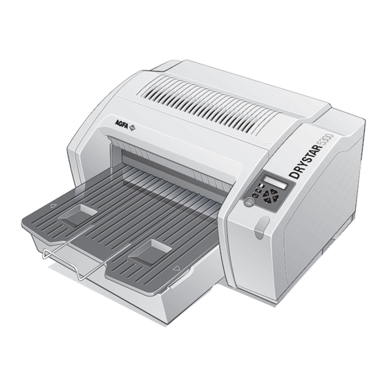
Overview of user interface controls Power/Reset button Display Keypad Status indicator LED Film input tray Film output tray Never try to open the printer when the Drystar 5300 is printing a film. Always follow the instructions on the display! 2921B EN 20031206... - Page 19 • To reset the printer. Do NOT press the Power/Reset button without first following the procedure to stop printing when the Drystar 5300 is printing a film. Refer ‘Switching off the Drystar 5300’ on page 30. 2921B EN 20031206...
- Page 20 Rear panel At the rear side of the printer, one slot and three connectors are available: • To insert an external CF-card for software CF-card slot installation, backup, etc. Network • To connect a remote PC (used for access via the connector web browser pages).
- Page 21 Inserting a CF-card To insert a CF-card in the Drystar 5300 (the slot is located at the rear side): Hold the CF-card vertically with the connector holes in front of the slot, and with the flat surface pointing to the left.
- Page 22 Removing a CF-card To remove a CF-card from the Drystar 5300 slot: Push the unlocking lever underneath the CF-card slot. The CF-card is pushed slightly outward. Remove the CF-card gently from the slot. 2921B EN 20031206...
- Page 23 The Drystar 5300 gives status information via beeps. The length of the beep indicates the response of the system to a key command. • A short beep means that Drystar 5300 has accepted the key command and is starting the operation. •...
- Page 24 (In key-operator mode) Confirm key • To select a menu. • To accept an entry in a menu. • To move the cursor to the previous entry field. • To scroll upwards. Up key • To increment the number in a(n) (alpha)numerical entry field.
- Page 25 The display The Drystar 5300 control panel has a backlit LCD display with 4 lines of 20 characters each (2 lines of 7 characters for Greek or Asian languages). Its lay-out depends on the operating mode. General display features The figure below shows how the display is illustrated in this manual:...
- Page 26 In operator mode, appropriate information is displayed in accordance with the status of the printer. The operator basic screen looks as follows, indicating that the Drystar 5300 is ready for operation and that no job is currently being executed. READY...
- Page 27 To accept an entry in a menu, press the Confirm key. • A short beep acknowledges and terminates the entry. • The Drystar 5300 will sound a long beep if you press a key that is not to be used at that moment. 2921B EN 20031206...
-
Page 28: Switching On The Drystar 5300
LED is constantly green. READY " It takes 13 minutes (starting up of the Drystar 5300 and heating up of the thermal print head) before you can start printing. The display will inform you that the printer is warming up:... - Page 29 • If, on the front panel display, the print queue screen is shown, the status indicator LED is green and blinking. Modaname 10:21:34 PR film 1 of 6 Modaname 10:21:34 CA xx Jobs in memory WA Make sure that the printer is loaded with appropriate consumables. "...
-
Page 30: Switching Off The Drystar 5300
Make sure that pending jobs are correctly finished. If necessary, follow the procedure to stop printing. Press the Power/Reset button to switch off the Drystar 5300. • If the printer is ready, it shuts down immediately: Power off initiated Please wait •... -
Page 31: Chapter 2: Basic Operation (Operator Mode)
Basic operation (operator mode) This chapter will inform on how to manage the print queue, how to print films with priority and how to load new films. Overview of operator functions Managing the print queue About Drystar 5300 consumables Loading films... -
Page 32: Overview Of Operator Functions
Overview of operator functions This section focuses on the basic operating principles of the Drystar 5300. After reading this chapter, the operator should be able to produce diagnostic usable hardcopies. No special technical skills are required. All basic operator functions can be activated directly by pressing a single key on the keypad. -
Page 33: Managing The Print Queue
Checking the print queue If jobs have been transmitted from the network to the Drystar 5300, they are put in the print queue on a first in, first out schedule. New jobs that are added to the queue get the ‘waiting’ status. - Page 34 A description of the possible status of the jobs is listed in the table below: Status Description Printing Printing of this job is in progress. The necessary calculations are already being Calculating made before printing of the job can be started. Waiting Jobs are queued in the printer memory.
-
Page 35: About Drystar 5300 Consumables
About Drystar 5300 consumables The Drystar 5300 can handle blue-transparent and clear-transparent films. Available film formats are 11x14” and 14x17”. When a new film pack is loaded, the Film Identification tag is read and the printer settings are automatically adjusted. -
Page 36: Loading Films
" The Drystar 5300 can be loaded with new films in full daylight. Loading films is easy and can be done very quickly. Follow the procedures as described in this section. The Drystar 5300 will inform you in several ways when a film tray is empty: • an audible signal, •... - Page 37 Wait while the printer finishes printing any current jobs. When the film path is cleared, proceed with step 3. When the Drystar 5300 is in the ready state and the input tray is empty: The display shows the following message:...
- Page 38 The printer is ready to receive a new film when the following message appears: - Remove cover sheet from tray - Load new film - Close tray Remove the white (protective) film sheet. Take film pack and slide it into the input tray. "...
- Page 39 Either remove the sticker completely, or leave it on the film bag; DO NOT leave it on the triangular flap! Slide the film pack completely into the input tray. 2921B EN 20031206...
- Page 40 Tear the plastic tape from around the film pack. Close the input tray. " The Drystar 5300 resumes printing as soon as the tray is closed. " Loading instructions are also available inside the input tray cover. 2921B EN 20031206...
- Page 41 Loading a single film in the input tray " When you load a single film sheet (e.g. after removing it from the input tray, or after film jam), make sure that it is correctly positioned. Refer to ‘Checking the correct position of a film in the input tray’ on page 42.
- Page 42 Checking the correct position of a film in the input tray " You can verify that the film is properly loaded by watching the lower right corner of the films in the input tray. The rounding of this corner should be smaller than the other three corners.
-
Page 43: Chapter 3: Advanced Operation (Key-Operator Mode)
Chapter Advanced operation (key-operator mode) This chapter gives an overview of functions for the advanced user: Overview of key-operator functions Quality control procedure Preventive maintenance schedule Cleaning the exterior Cleaning the print head resistor line Troubleshooting checklist... -
Page 44: Overview Of Key-Operator Functions
The key-operator menus make it possible to use the Drystar 5300 advanced functions. " These functions are described in detail in the Drystar 5300 Reference manual. For general information on the key functions of the Drystar 5300, refer to ‘The user interface’ on page 18. -
Page 45: Quality Control Procedure
In order to establish and maintain constant image quality, a regular evaluation of the image quality is advised. The Drystar 5300 Imager contains an automatic QC feature designed to maintain optimum image quality. The QC procedure consists of two main steps: •... - Page 46 Establishing the reference values and verifying image quality After installation of a new Drystar 5300 Imager and before initial use you must establish Quality Control aim values. These values will be used as the base line for comparison when daily Quality Control is done. These values should be determined again after major service or repair.
- Page 47 Base+Fog density, • Mid density, • DD (Density Difference), • MaxD (Maximum Density). By default, the internal densitometer of the Drystar 5300 will be used. The internal densitometer of the Drystar 5300 is calibrated at installation. Authorized service personnel should recalibrate internal densitometer annually or after major service or repair.
- Page 48 After the image is printed, the Drystar 5300 will display the optical density values: QC readings: Base+Fog x.xx Mid Density x.xx DD x.xx MaxD x.xx (densitometer=xxxxx) The displayed values represent the following steps on the test film: • Base+Fog -The density value of the Base + Fog step.
- Page 49 " The calculated ‘Operating levels’ should respect the following tolerances: Operating level Tolerance Base + Fog - 0.03 / + 0.05 Mid Density +/- 0.20 DD (Density Difference) +/- 0.20 MaxD +/- 0.25 " The tolerances may be different according to local regulations. These charts will be used for the daily quality test.
- Page 50 Print the 'QC ' test image or use the previously printed QC test image used to establish the daily operating density levels. You should obtain an image looking like this: Drystar 5300 Quality Control Test Image Initials : _____ Date : __________...
- Page 51 (use a magnifying glass and optimize viewing conditions). Record these values at the top of the Drystar 5300 Chart 3 (‘Drystar 5300 Artifacts and Spatial Resolution Control Chart’). Refer to Appendix B ‘Quality...
- Page 52 To establish the image geometry reference values, proceed as follows: Print the 'QC ' test image or use the previously printed QC test image. You should obtain an image looking like this: Drystar 5300 Quality Control Test Image Initials : _____ Date : __________...
- Page 53 0.5 mm divisions (1/64 inch). Record these values as reference dimensions A and B on the Drystar 5300 Chart 4 (‘Drystar 5300 Geometric Consistency Control Chart’). Refer to Appendix C ‘Quality Control Charts’ on page 71. These charts will be used for the annual quality test. For more information, refer to ‘Performing the annual QC test (Geometric Consistency Test)’...
- Page 54 Performing the daily QC test This test must be performed every day before any clinical film can be processed. Switch on the Drystar 5300 and wait for at least 15 minutes. Refer to ‘Switching on the Drystar 5300’ on page 28.
- Page 55 (NO) to quit. QC procedure in progress Please wait The Drystar 5300 will automatically print the QC test image. After the QC test image is printed, the Drystar 5300 will display the optical density values: QC readings: Base+Fog x.xx Mid Density x.xx DD x.xx MaxD x.xx...
- Page 56 3 groups, each having 5 dots. All five dots of each group must be visible (use a magnifying glass and optimize viewing conditions). Record the results on Drystar 5300 Chart 3 (Drystar 5300 ‘Artifacts and Spatial Resolution Control Chart’). Refer to Appendix B ‘Quality Control...
- Page 57 We strongly recommend using a 30-cm (12-inch) machinist scale with 0.5 mm divisions (1/64 inch). Record these values as measured dimensions A and B on the Drystar 5300 Chart 4 (‘Drystar 5300 Geometric Consistency Control Chart’). Refer to Appendix B ‘Quality Control Charts’...
-
Page 58: Preventive Maintenance Schedule
Do not touch the resistor line of the print head. • Always switch off the Drystar 5300 and disconnect the power cord from the outlet before carrying out any maintenance work inside the printer. " Film jam removal or cleaning the printer head can be done without switching the power off. -
Page 59: Cleaning The Exterior
Cleaning the exterior Switch off the Drystar 5300 by following the procedure as described in ‘Switching off the Drystar 5300’ on page 30. Remove the power plug from the socket. Wipe the exterior of the printer with a clean, soft, damp cloth. -
Page 60: Cleaning The Print Head Resistor Line
For more information on maintaining image quality, refer to ‘Image quality problems’ on page of the Drystar 5300 Reference manual. To clean the print head: Press the Key-operator key to enter the key-operator mode. On the key-operator main menu, press the Down key five times, followed by the Confirm key to select ‘Calibration’. - Page 61 Open the top cover. As soon as the top cover is opened, the ‘Thermal head cleaning’ screen continues giving the following instructions: THERMAL HEAD CLEANING - Clean thermal head - Close top cover Open the hold-down bracket. 2921B EN 20031206...
- Page 62 Open the print head unit. The print head unit can be warm. Locate and check on sight the print head resistor line. " Be careful not to touch the print head resistor line with your fingers. 2921B EN 20031206...
- Page 63 Clean the print head resistor line. Gently pass over the resistor line a few times with a lint free cloth, slightly moistened with Isopropyl alcohol or Ethanol. Do this only in one direction, i.e. from left to right, without lifting the cloth. "...
-
Page 64: Troubleshooting Checklist
Troubleshooting checklist The table below lists some general problems which can occur when working with the Drystar 5300. Refer to the appropriate pages of the Drystar 5300 Reference manual. • The Drystar 5300 does not print. Action Refer to Page ‘Checking the status indicator LED’... -
Page 65: Appendix A: Equipment Information Sheet
Appendix Equipment information sheet... -
Page 66: Specifications
Specifications Product description Type of product Printer Commercial name Drystar 5300 Original seller/manufacturer Agfa-Gevaert N.V. Labeling TÜV-Certification Mark cUL-Certification Mark, CE-marking Dimensions • Unpacked: width 67, length 80, height 36 Dimensions (approx. values in cm) • Packed: width 80, length 106, height 61 •... - Page 67 Network connectivity RJ45 twisted pair for 100Base-TX; Ethernet / connectors Serial RS232 connection Network protocols (TCP/IP services) FTP, Telnet, HTTP, SMTP DICOM (Default) Image formats TIFF Postscript Not available Power consumption During operation 250 W In standby 40 W Protection against Electrical shocks Class 1 (grounded) Ingress of water...
- Page 68 Direct thermal printing Reliability Estimated product life (if regularly serviced and maintained > 5 years and > 125,000 films according to Agfa instructions) Service interventions Max. 2 interventions / 3 years Earthquake kit (standard) Meets the CA requirements 2921B EN 20031206...
-
Page 69: Options And Accessories
Hardware The OPTIONAL mobile/earthquake installation kit allows you to use the Drystar 5300 in a van, or to use it in unstable environment. It contains the necessary equipment to fix the printer onto a table. The mobile/earthquake installation kit is delivered with the necessary mounting instructions. - Page 70 Connectivity with Agfa equipment • Paxport • MG3000 • ADC 70 • ADC Compact • ADC Compact Plus • ADC Solo • Impax • DR-Thorax Connectivity with non-Agfa equipment From a connectivity point of view, every connection to a modality supporting "DICOM print"...
-
Page 71: Appendix B: Quality Control Charts
Appendix Quality Control Charts... - Page 72 Chart 1 Drystar 5300 Imager: Determination of Operating Levels Imager Type: __________ Serial #: _________________ Date ____________________ Film Type: ____________ Emulsion #: ______________ Densitometer (Internal or External ) If External: Type ____________ Serial #: _________________ Step 1: Print QC Test images on five consecutive days. Record the optical densities measurements in the tables below.
- Page 73 Chart 2A Drystar 5300 Imager Daily Density Control Chart Imager Type: __________ Serial #: _____________ Film Type:____________ Emul #:___________ Densitometer (Internal or External ) If External: Type _______________ Serial #:________________ ate: Initials: Upper Control limit = Mid Density (Density closest to 1.20) +0.20...
- Page 74 Chart 2B Drystar 5300 Imager Daily Density Control Chart Imager Type: __________ Serial #: _____________ Film Type:____________ Emul #:___________ Densitometer (Internal or External ) If External: Type _______________ Serial #:________________ ate: Initials: Upper Control limit = +0.05 Base + Fog Aim...
- Page 75 Chart 3 Drystar 5300 Imager Artifacts and Spatial Resolution Control Chart Test Frequency: Weekly Drystar 5300 Serial # _____________ Initial Reference Test Date Initial Reference Artifacts Initial Reference Dot Visibility Month Artifacts Visibility of all Dots Month Artifacts Visibility of all Dots...
- Page 76 Chart 4 Drystar 5300 Imager Geometric Consistency Control Chart Test Frequency: Annually or as required Drystar 5300 Serial # ______________ Reference Dimensions Measured Dimensions Consistency Aspect Ratio Date: Date: Reference Dimensions Measured Dimensions Consistency Aspect Ratio Date: Date: 2921B EN 20031206...
- Page 77 2921B EN 20031206...
- Page 78 Printed in Belgium Published by Agfa-Gevaert N.V., B-2640 Mortsel-Belgium 2921B EN 20031206...
Need help?
Do you have a question about the Drystar 5300 and is the answer not in the manual?
Questions and answers