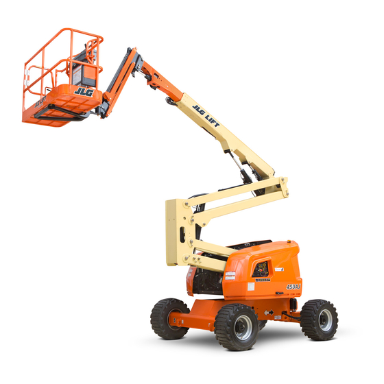
JLG 450A series II Service And Maintenance Manual
Hide thumbs
Also See for 450A series II:
- Operation and safety manual (134 pages) ,
- Operation and safety manual (112 pages)

Related Manuals for JLG 450A series II


Summary of Contents for JLG 450A series II
- Page 1 Service and Maintenance Manual Model 450A Series II 450AJ Series II S/N 0300160835 to Present P/N - 3121290 October 4, 2013...
- Page 2 NOTE: This manual also applies to machines with the following Serial Numbers: 0300159794, 0300159795, 0300160088, and 0300160456.
-
Page 3: Bhydraulic System Safety
REPLACEMENT OF ELECTRICAL COMPONENTS. • KEEP ALL SUPPORT EQUIPMENT AND ATTACHMENTS STOWED IN THEIR PROPER PLACE. • USE ONLY APPROVED, NONFLAMMABLE CLEANING SOL- VENTS. 3121290 – JLG Lift –... - Page 4 INTRODUCTION REVISON LOG Original Issue January 10, 2013 Revision 1 October 4, 2013 – JLG Lift – 3121290...
-
Page 5: Table Of Contents
Do NOT Do the Following When Welding on JLG Equipment ....... - Page 6 Installation ................. . . 3-60 – JLG Lift –...
- Page 7 Diagnostic Aids ................3-93 3121290 – JLG Lift –...
- Page 8 Installing Counterbalance Valve............. . . 4-18 – JLG Lift –...
- Page 9 Articulating Jib (AJ Only) ..............5-67 3121290 – JLG Lift –...
- Page 10 Connect JLG Control System Analyzer ........
- Page 11 Deutz EMR 2 Troubleshooting Flow Chart ............3-67 3121290 – JLG Lift –...
- Page 12 Main Lift Cylinder................. . . 5-10 viii – JLG Lift – 3121290...
- Page 13 Cylinder Head Removal ................5-37 3121290 – JLG Lift –...
- Page 14 Resistance Measurement ................7-2 – JLG Lift –...
- Page 15 Four Wheel Drive Hydraulic Schematic - 2 of 2 ............7-23 3121290 – JLG Lift –...
- Page 16 Help Fault Codes, Displayed Faults, and Descriptions ..........6-41 – JLG Lift –...
-
Page 17: Specifications
25 ft. 9.5 in. (7.56 M) (cold) Up & Over Height-450AJ SII 25 ft. 10 in. (7.57 M) Drive Hub 23.75 oz. (0.7 liters) Main Boom Up Angle 75° Drive Brake 2.7 oz. (0.08 liters) Main Boom Down Angle -24° 3121290 – JLG Lift –... -
Page 18: 1.5 Tires
48.8 hp (36.4 kW) Bore 3.6 in. (92 mm) Stroke 4.3 in. (110 mm) Displacement 177 cu. in. (2.9L) Oil Capacity w/filter 9.4 Qt (8.9 L) Compression Ratio 18.4:1 Firing Order 1-3-4-2 Max. RPM 2600 – JLG Lift – 3121290... -
Page 19: 1.8 Hydraulic Oil
DTE13. Pour Point, Max -58°F (-50°C) Viscosity ASIDE FROM JLG RECOMMENDATIONS, IT IS NOT ADVISABLE TO MIX OILS OF DIF- at 0° C (32° F) 340 cSt (1600SUS) FERENT BRANDS OR TYPES. THEY MAY NOT CONTAIN REQUIRED ADDITIVES OR BE at 40°... -
Page 20: 1.9 Serial Number Location
A serial number plate is affixed to left rear side of frame. If serial number plate is damaged or missing, machine serial number is stamped on left side of frame. Figure 1-1. Serial Number Locations – JLG Lift – 3121290... -
Page 21: Operator Maintenance And Lubrication Diagram
SECTION 1 - SPECIFICATIONS Figure 1-2. Operator Maintenance and Lubrication Diagram 3121290 – JLG Lift –... -
Page 22: 1.10 Operator Maintenance
Interval - Every 3 months or 150 hrs of operation OVERGREASING BEARINGS WILL RESULT IN DAMAGE TO OUTER SEAL IN HOUSING. DO NOT OVERGREASE BEARINGS. NOTE: If necessary, install grease fitting into worm gear housing and grease. Replace fitting with pipe plug when complete. – JLG Lift – 3121290... - Page 23 Interval - Change after first 50 hrs. and every 6 months Interval - Check Level daily; Change every 2 years or or 300 hrs. thereafter or as indicated by Condition 1200 hours of operation. Indicator. 3121290 – JLG Lift –...
-
Page 24: Deutz Engine Dipstick Markings
Interval - Every Year or 600 hours of operation Comments - Check level daily/Change in accordance with engine manual. 10. Oil Change w/Filter - GM Fill Cap/Spin-on Element (JLG P/N7016641) Capacity - 11 Qt (10.5 L) Crankcase; 5 Qt (4.7 L) Cooler Lube - EO... - Page 25 Comments - Replace filter. Refer to Propane Fuel Filter Replacement in Section 3. Lube Point(s) - Replaceable Element Interval - Every 6 months or 300 hours of operation or as indicated by the condition indicator 3121290 – JLG Lift –...
-
Page 26: Torque Chart (Sae Fasteners - Sheet 1 Of 7)
1. THESE TORQUE VALUES DO NOT APPLY TO CADMIUM PLATED FASTENERS 2. ALL TORQUE VALUES ARE STATIC TORQUE MEASURED PER STANDARD AUDIT METHODS TOLERANCE = ±10% 3. * ASSEMBLY USES HARDENED WASHER REFERENCE JLG ANAEROBIC THREAD LOCKING COMPOUND JLG P/N Loctite® P/N... -
Page 27: Torque Chart (Sae Fasteners - Sheet 2 Of 7)
1. THESE TORQUE VALUES DO NOT APPLY TO CADMIUM PLATED FASTENERS 2. ALL TORQUE VALUES ARE STATIC TORQUE MEASURED PER STANDARD AUDIT METHODS TOLERANCE = ±10% 3. * ASSEMBLY USES HARDENED WASHER Figure 1-5. Torque Chart (SAE Fasteners - Sheet 2 of 7) 3121290 – JLG Lift – 1-11... -
Page 28: Torque Chart (Sae Fasteners - Sheet 3 Of 7)
4. CLAMP LOAD LISTED FOR SHCS IS SAME AS GRADE 8 OR CLASS 10.9 AND DOES NOT REPRESENT FULL STRENGTH CAPABILITY OF SHCS. IF HIGHER LOAD IS REQUIRED, ADDITIONAL TESTING IS REQUIRED. Figure 1-6. Torque Chart (SAE Fasteners - Sheet 3 of 7) 1-12 – JLG Lift – 3121290... -
Page 29: Torque Chart (Sae Fasteners - Sheet 4 Of 7)
4. CLAMP LOAD LISTED FOR SHCS IS SAME AS GRADE 8 OR CLASS 10.9 AND DOES NOT REPRESENT FULL STRENGTH CAPABILITY OF SHCS. IF HIGHER LOAD IS REQUIRED, ADDITIONAL TESTING IS REQUIRED. Figure 1-7. Torque Chart (SAE Fasteners - Sheet 4 of 7) 3121290 – JLG Lift – 1-13... -
Page 30: Torque Chart (Metric Fasteners - Sheet 5 Of 7)
4. CLAMP LOAD LISTED FOR SHCS IS SAME AS GRADE 8 OR CLASS 10.9 AND DOES NOT REPRESENT FULL STRENGTH CAPABILITY OF SHCS. IF HIGHER LOAD IS REQUIRED, ADDITIONAL TESTING IS REQUIRED. Figure 1-8. Torque Chart (METRIC Fasteners - Sheet 5 of 7) 1-14 – JLG Lift – 3121290... -
Page 31: Torque Chart (Metric Fasteners - Sheet 6 Of 7)
4. CLAMP LOAD LISTED FOR SHCS IS SAME AS GRADE 8 OR CLASS 10.9 AND DOES NOT REPRESENT FULL STRENGTH CAPABILITY OF SHCS. IF HIGHER LOAD IS REQUIRED, ADDITIONAL TESTING IS REQUIRED. Figure 1-9. Torque Chart (METRIC Fasteners - Sheet 6 of 7) 3121290 – JLG Lift – 1-15... -
Page 32: Torque Chart (Metric Fasteners - Sheet 7 Of 7)
4. CLAMP LOAD LISTED FOR SHCS IS SAME AS GRADE 8 OR CLASS 10.9 AND DOES NOT REPRESENT FULL STRENGTH CAPABILITY OF SHCS. IF HIGHER LOAD IS REQUIRED, ADDITIONAL TESTING IS REQUIRED. Figure 1-10. Torque Chart (METRIC Fasteners - Sheet 7 of 7) 1-16 – JLG Lift – 3121290... -
Page 33: General
Industries, Inc. recognizes a Factory-Trained Service Technician into service. as a person who has successfully completed the JLG Service Training School for the subject JLG product model. Reference Preparation, Inspection, and Maintenance machine Service and Maintenance Manual and appropriate JLG inspection form for this inspection. -
Page 34: Service And Guidelines
Prior to each sale, lease, or Owner, Dealer, or User Qualified JLG Mechanic Service and Maintenance Manual rental delivery. and applicable JLG inspection form. Frequent Inspection In service for 3 months or 150 hours, whichever Owner, Dealer, or User Qualified JLG Mechanic Service and Maintenance Manual comes first;... -
Page 35: Component Disassembly And Reassembly
Lubrication Chart in Section 1. Clean battery using a non-metallic brush and a solution of baking soda and water. Rinse with clean water. After cleaning, thoroughly dry battery and coat terminals with an anti corro- sion compound. 3121290 – JLG Lift –... -
Page 36: Lubrication And Information
If cylinder passes this test, it is acceptable. for assistance in selecting the proper equivalent. Avoid NOTE: This information is based on 6 drops per minute cylinder mixing petroleum and synthetic base oils. JLG Industries recommends changing hydraulic oil annually. leakage. -
Page 37: Pins And Composite Bearing Repair Guidelines
2. Filament wound bearings should be replaced if any of • Ground only to structure being welded. the following is observed: Do NOT Do the Following When Welding on JLG a. Frayed or separated fibers on the liner surface. b. Cracked or damaged liner backing. -
Page 38: Inspection And Preventive Maintenance Schedule
Turntable Lock 1,2,5 1,2,5 Hood, Hood Props, Hood Latches 1,2,5 Chassis Assembly Tires 16,17 16,17,18 16,17,18 Wheel Nuts/Bolts Wheel Bearings 14,24 Oscillating Axle/Lockout Cylinder Systems Extendable Axle Systems Steer Components Spindle Thrust Bearing/Washers Drive Hubs – JLG Lift – 3121290... - Page 39 Electrical Connections Instruments, Gauges, Switches, Lights, Horn 5,23 General Operation and Safety Manuals in Storage Box ANSI and AEM Manuals/Handbooks Installed (ANSI Mar- kets Only) Capacity Decals Installed, Secure, Legible All Decals/Placards Installed, Secure, Legible 3121290 – JLG Lift –...
- Page 40 Function Test of All Systems 21, 22 Paint and Appearance Stamp Inspection Date on Frame Notify JLG of Machine Ownership Footnotes: Prior to use each day; or at each Operator change Prior to each sale, lease, or delivery In service for 3 months or 150 Hours; or Out of service for 3 months or more; or Purchased used...
-
Page 41: Chassis & Turntable
Pneumatic tire air pressure must be equal to air pressure sten- Manual for part number of approved tires for a particular ciled on side of JLG product or rim decal for safe and proper machine model. If not using a JLG approved replacement tire, machine operation. -
Page 42: Wheel Installation
Check torque every 3 months or 150 hours of operation. Table 3-1. Wheel Torque Chart TORQUE SEQUENCE 1st Stage 2nd Stage 3rd Stage 40 ft-lb (55 Nm) 100 ft-lb (130 Nm) 170 ft-lb (255 Nm) – JLG Lift – 3121290... -
Page 43: 3.2 Torque Hub
O-rings or gaskets meet unit exterior, then checking for air bubbles. Replace part immediately if you detect a leak in a seal, O-ring, or gasket. 3121290 – JLG Lift –... -
Page 44: Drive Hub And Brake Assembly (2Wd And 4Wd)
SECTION 3 - CHASSIS & TURNTABLE Figure 3-3. Drive Hub and Brake Assembly (2WD and 4WD) – JLG Lift – 3121290... -
Page 45: Drive Hub And Brake Assembly (2Wd And 4Wd) Parts List
Cover Plate Capscrew O-Ring Lockwasher Disconnect Rod O-Ring Disengage Cap Back-up Ring Bolt O-Ring Pipe Plug Back-up Ring Rivet Dowel Pin I.D. Plate Plug Input Shaft Assembly Plug Shaft Spring (Natural) Retaining Ring Spring (Blue) Spring 3121290 – JLG Lift –... -
Page 46: Drive Hub (4Wd Front Only)
SECTION 3 - CHASSIS & TURNTABLE Figure 3-4. Drive Hub (4WD Front Only) – JLG Lift – 3121290... -
Page 47: Drive Hub (4Wd Front Only) Parts List
Carrier Assembly Retaining Ring Carrier Spring Retaining Ring Thrust Spacer Needle Bearing Gear, Sun Thrust Washer Thrust Washer Planet Shaft Bolt Planet Gear Pin, Dowel Roll Pin Coupling Ring Gear Input Spacer O-Ring Input Spacer O-Ring 3121290 – JLG Lift –... -
Page 48: Main Disassembly For "B" Drives
9. Press nine studs (1N) out of stud holes in hub (1G). 16. Remove O-ring (5) from counterbore in hub (1G). Dis- 10. Hub-spindle disassembly is complete. card O-ring. 17. Main disassembly for ”B” drives is complete. – JLG Lift – 3121290... -
Page 49: Cover Disassembly
6. Remove remaining 16 needle rollers (3C) from other side of cluster gear (3F). Discard needle rollers. 7. Repeat steps 1-6 to remove and disassemble two remaining cluster gears. 8. At this point carrier disassembly is complete. 3121290 – JLG Lift –... - Page 50 (3E). 10. Repeat steps 1 thru 9 to assemble and install two remaining cluster gears. 11. At this point carrier sub-assembly is complete. 3-10 – JLG Lift – 3121290...
-
Page 51: Cover Sub-Assembly
(6B) and tighten bolts. flange of cover cap. 6. Using a torque wrench, apply 36 to 49 in-lb (4 to 5 Nm) of 3. Insert disconnect rod (6E) into cover cap (6B). torque to both bolts (6C). 3121290 – JLG Lift – 3-11... -
Page 52: Hub-Spindle Sub-Assembly
(1G). 9. Using a torque wrench, apply 36 to 49 in-lb (4 to 5 Nm) of torque to both bolts (6C). 2. Press nine studs (1N) in stud holes in hub (1G). 3-12 – JLG Lift – 3121290... - Page 53 (1G). 8. Press bearing cone (1F) on spindle (1A) in hub (1G). 5. Set hub (1G) on large end. Place bearing cone (1D) into bearing cup (1C). 3121290 – JLG Lift – 3-13...
-
Page 54: Main Assembly
2. Oil exposed surfaces inside hub (1G).Place internal gear 11. At this point hub-spindle sub-assembly is complete. (2) in hub (1G) so its internal splines mesh with external splines of spindle (1A). Oil internal gear (2). 3-14 – JLG Lift – 3121290... - Page 55 (7A) by compressing spring and spacers together. 5. Place spring (7C) on smooth end of input shaft (7A). 8. With large splined end down, place input shaft sub- assembly (7) into spindle (1A). 3121290 – JLG Lift – 3-15...
-
Page 56: Cluster Gear Punch Marks
(3F). NOTE: This will hold punch marks in position while installing car- rier into hub. 14. Oil all exposed surfaces inside hub (1G). Place thrust washer (11) into counterbore in top of carrier. 3-16 – JLG Lift – 3121290... - Page 57 16. Place cover sub-assembly (6) on ring gear (4). Align pipe plug holes before disassembly. 20. Place 12 bolts in remaining bolt holes in cover (6) and tighten. 17. Place four flat washers (16) on top of bolt holes in cover sub-assembly. 3121290 – JLG Lift – 3-17...
- Page 58 22. Turn hub (1G) on its side. Insert coupling (14) into end of spindle (1A). 24. Leak test unit at a pressure of 5 psi (34.47 kPa) for 2 to 3 minutes. 25. At this point main assembly is complete. 3-18 – JLG Lift – 3121290...
-
Page 59: Tool List
4. T-109691 ASSEMBLY PRESSING TOOL FOR CONE (1F). * These tools are for specific seals, cups or cones. There is a specific tool for each cup and cone. 2. T-138903 ASSEMBLY PRESSING TOOL FOR CUP (1C). 3121290 – JLG Lift – 3-19... -
Page 60: 3.3 Re-Align Torque Hub Input Coupling
5. Disconnect hydraulic power supply and reconnect line Bias spring to brake release port. Servo piston Minimum Swashplate Angle Stop Output Shaft Cylinder Block Shaft Seal Piston Bearing Endcap Slipper Valve plate Figure 3-6. Drive Motor Cross Section 3-20 – JLG Lift – 3121290... -
Page 61: Shaft Seal Replacement
5. Install new O-rings (6, 4, and 5). 6. Use 1/4" hex wrench to torque plug (3) to 20 ft-lb (27 Nm). 7. Use 11/16" internal hex and torque plugs (2 and 1) to 27 ft-lb (37 Nm). 3121290 – JLG Lift – 3-21... -
Page 62: Troubleshooting
Ensure proper control orifices are installed in motor and check they are not fices are properly installed and not fice, the longer time it takes to shift the motor. Obstruction also increases obstructed. Clean or replace as needed. obstructed. shift times. 3-22 – JLG Lift – 3121290... -
Page 63: Disassembly
11. Using a 5/16" internal hex wrench, remove drain plugs (19, 20). Discard O-rings. 12. If equipped with axial ports, use a 9/16" an internal hex wrench and remove work port plugs (21). Discard O-rings. 3121290 – JLG Lift – 3-23... -
Page 64: End Cap
After shaft is removed, insert it into bearing cavity and tap lightly with a soft mallet on the splined end. Grease will force out bearing. 18. Remove minimum angle stop (29) and servo spring (30) from housing. 3-24 – JLG Lift – 3121290... -
Page 65: Cylinder Kit
36. Bearing 37. Shaft Figure 3-15. Shaft & Front Bearing 21. Remove inner snap ring (35) and shaft/bearing assembly. 22. Remove snap ring (36) retaining shaft front bearing. Pull bearing (37) off shaft (38). 3121290 – JLG Lift – 3-25... -
Page 66: Swash Plate & Servo Piston
NOTE: Most repairs do not require block spring removal. Perform release pressure and remove outer block spring washer this procedure only if you suspect problems with the block (50), block spring (52), and inner block spring washer spring. (53) from cylinder block. 3-26 – JLG Lift – 3121290... -
Page 67: Inspection
Table 3-9. Cylinder Block Measurements Measurement Minimum Cylinder Block Height (A) 50.8 (2.00) 50.8 (2.00) 50.8 (2.00) 54.4 (2.14) 54.4 (2.14) Cylinder Block Surface Flatness 0.002 0.002 0.002 0.002 0.002 (0.0000079) (0.0000079) (0.0000079) (0.0000079) (0.0000079) 3121290 – JLG Lift – 3-27... - Page 68 [0.0001 in] 25.8 mm [1.015 in] 24.6 mm [0.969 in] Thickness equality side to side: LOOP FLUSHING SPOOL 0.05 mm [0.002 in] Inspect loop flushing spool. Check for cracks or damage. Replace as needed. 3-28 – JLG Lift – 3121290...
-
Page 69: Assembly
Align piston with ball socket facing inside of housing. Figure 3-19. Cylinder Kit Assembly 4. Turn block over and install retaining ring (8), hold-down pins (9), and ball guide (10) to cylinder block. 3121290 – JLG Lift – 3-29... -
Page 70: Swash Plate And Journal Bearing
Figure 3-20. Swash Plate and Journal Bearing 7. Install swashplate (14) in housing. Tilt swashplate and guide servo lever ball into its socket in servo piston rod. Ensure swashplate seats into journal bearings and moves freely. Lubricate swashplate running surface. 3-30 – JLG Lift – 3121290... -
Page 71: Cylinder Kit Installation
Apply a liberal coat of assembly grease to endcap side of valve plate to keep it in place during installation. 20. Servo Spring 21. Minimum Angle Stop Figure 3-23. Servo Spring and Minimum Angle Stop 3121290 – JLG Lift – 3-31... -
Page 72: End Cap
17. Before installing shaft seal, ensure shaft turns smoothly with less than 120 in-lb (13.5 Nm) of force. If shaft does not turn smoothly within specified force, disassemble and check unit. Figure 3-27. Plugs and Fittings Installation 3-32 – JLG Lift – 3121290... -
Page 73: Initial Start-Up Procedures
9. Shut down engine and remove pressure gauge. Replace Figure 3-28. Loop Flushing Spool plug at charge pressure gauge port. 10. Check fluid level in reservoir; add clean filtered fluid if necessary. Motor is now ready for operation. 3121290 – JLG Lift – 3-33... -
Page 74: Chassis Torque Values
SECTION 3 - CHASSIS & TURNTABLE Table 3-10. Chassis Torque Values Ft-Lb Figure 3-29. Chassis Torque Values 3-34 – JLG Lift – 3121290... -
Page 75: 3.5 Adjustment Procedure For Lockout Valve
2. Bracket 3. Lockout Valve Figure 3-30. Valve Adjustment 2. Ideal adjustment is 3/8" (9.5 mm). Do not push plunger in more than 3/8" (9.5 mm). The extra adjustment is needed for turntable bearing play. 3121290 – JLG Lift – 3-35... -
Page 76: Oscillating Axle Lockout Test
Also needed are a shim and seal kit (refer to JLG Parts Manual), 3/4" steel rod at least 10" 1. Place a 6" (15 cm) high block with ascension ramp in long, silicone sealant Mobil SHC 460 grease, Lubriplate No. -
Page 77: Swing Bearing Installation
SECTION 3 - CHASSIS & TURNTABLE Inner Race Outer Race Figure 3-31. Swing Bearing Installation 3121290 – JLG Lift – 3-37... -
Page 78: Disassembly
(15) between cover plate and cap. NOTE: If there are five screws or drive screws holding cover plate to cap, a new cap (12) should be ordered. This is an older version; new cover plate has six holes. 3-38 – JLG Lift – 3121290... -
Page 79: Swing Bearing Drive
SECTION 3 - CHASSIS & TURNTABLE Figure 3-32. Swing Bearing Drive 3121290 – JLG Lift – 3-39... -
Page 80: Assembly
80 ft-lb (108.5 Nm). bearing with Mobil SHC 460 grease. Reinstall plugs. 14. Install pinion/gear assembly in housing so gear teeth mesh with worm gear teeth. 15. Apply silicone sealant to cap assembly contact area on housing. 3-40 – JLG Lift – 3121290... -
Page 81: Swing Bearing (Dohi) Torque Sequence
TURNTABLE. JLG INDUSTRIES RECOMMENDS ALL REMOVED GRADE 8 BEAR- ING NUTS AND BOLTS BE DISCARDED AND REPLACED WITH NEW NUTS AND BOLTS. IT IS IMPERATIVE THAT REPLACEMENT HARDWARE MEETS JLG SPECI- FICATIONS. USE OF GENUINE JLG HARDWARE IS HIGHLY RECOMMENDED. -
Page 82: Turntable Bearing Mounting Bolt Checks
600 hours of machine operation thereafter. Replace missing or loose bolts with new bolts and torque as specified after lubricating bolt threads with JLG Thread Locking Compound PN 0100019. Recheck all bolts for looseness after replacing and torquing individual bolts. -
Page 83: 3.8 Swing Motor
ABUSE CLOSELY FITTED PARTS. Matched Rotor Set Wear Plate Housing Manifold Outer Shaft Seal Coupling Shaft Bearing Drive Link - 12 Tooth Splines End Cover Matched Commutator Set Figure 3-39. Swing Motor - Cutaway 3121290 – JLG Lift – 3-43... -
Page 84: Removal
• Clean and dry motor before disassembly. 5. Carefully pull the swing motor from the swing drive. • As you disassemble motor, clean all parts except seals in clean petroleum-based solvent and blow them dry. 3-44 – JLG Lift – 3121290... -
Page 85: Swing Motor Removal And Installation
MOTOR. IF IT STAR TS TO PULL OUT WITH THE SWING MOTOR, IT CAN DAMAGE INTERNAL SEALS. Torque swing motor Swing mounting bolts to Motor 85 ft-lb (115 Nm). Figure 3-40. Swing Motor Removal and Installation 3121290 – JLG Lift – 3-45... -
Page 86: Disassembly And Inspection
2. Scribe an alignment mark down and across motor com- ponents from end cover (2) to housing (18) for proper reassembly orientation. 4. Remove end cover assembly (2) and seal ring (4). Discard seal ring. 3-46 – JLG Lift – 3121290... - Page 87 If any of these conditions exist. NOTE: Manifold consists of plates bonded together and cannot be disassembled. Compare both sides of manifold to ensure same surface is reassembled against rotor set. 3121290 – JLG Lift – 3-47...
- Page 88 Mark all rotor components and mating spline com- ponents for exact repositioning at assembly for maximum wear life and performance of rotor set and motor. 3-48 – JLG Lift – 3121290...
- Page 89 Inspect coupling shaft bearing and seal sur- faces for spalling, nicks, grooves, severe wear or corro- sion and discoloration. Inspect for damaged or worn internal and external splines or keyway. Replace shaft if any of these conditions exist. 3121290 – JLG Lift – 3-49...
- Page 90 If housing has passed this inspection, disassembly of motor is complete. 11. Remove housing (18) from vise. Invert housing and remove seal (20) with a blind hole bearing or seal puller. Discard seal. 3-50 – JLG Lift – 3121290...
- Page 91 Remove thrust washers (14) and bearings/bushings. This ensures correct reassembly of thrust bearing (15) if previously retained in housing by new bearings/bushings. bearing (13). 3121290 – JLG Lift – 3-51...
-
Page 92: Swing Motor - Exploded View
8C. Stator Vane 11. Coupling Shaft 14. Thrust Bearing 18. Bearing 8D. Stator Half 4. O-Ring 8. Rotor Set 12A. Key 15. Inner Shaft Seal 19. Outer Shaft Seal Figure 3-41. Swing Motor - Exploded View 3-52 – JLG Lift – 3121290... -
Page 93: Assembly
NOTE: Bearing mandrel must be pressed against lettered end of bearing shell. Housing bore must be square with press base and bearing/bushing not cocked when pressing a bearing/ bushing into housing. 3121290 – JLG Lift – 3-53... - Page 94 (12) to prevent damage to seal. 5. Assemble a new backup ring (17), new backup washer (25), and new seal (16) with seal lip facing toward inside of motor, into their counterbores in housing (18). 3-54 – JLG Lift – 3121290...
- Page 95 Coupling shaft must rotate smoothly on thrust bearing coupling shaft splines. package. NOTE: Use alignment marks on coupling shaft and drive link before disassembly to assemble drive link splines in their original position in mating coupling shaft splines. 3121290 – JLG Lift – 3-55...
- Page 96 Manifold surface that contacts rotor set has a series of irregular shaped cavities on largest circumference or cir- cle around inside diameter. Polished impression left on manifold by rotor set is another indication of which surface must contact rotor set. 3-56 – JLG Lift – 3121290...
- Page 97 5 bolt holes be sure cover holes are 17. Install commutator ring (6) over alignment studs on aligned with 5 threaded holes in housing (18). Correct 5 manifold. bolt end cover bolt hole relationship to housing port bosses is shown: 3121290 – JLG Lift – 3-57...
- Page 98 25-30 ft-lb (34-41 Nm). NOTE: If end cover has a valve (24) or five bolt holes, use line scribed on cover to radially align end cover to its original position. 3-58 – JLG Lift – 3121290...
-
Page 99: One Piece Stator Assembly
(9) with rotor splines into mesh with drive link (10) splines. Remove two bolts (1) if used to retain stator and wear plate. Go to Step 14 on page 3-56 to continue assembly. 3121290 – JLG Lift – 3-59... -
Page 100: Two Piece Stator Assembly
2. Secure swing motor to swing drive assembly with two and assembled vanes (8C) into stator half, creating nec- bolts and flat washers. Apply JLG threadlocker P/N essary clearance to assemble seventh or full comple- 0100019 to threads of retaining bolts. Torque to 85 ft-lb ment of seven vanes. -
Page 101: Auxiliary Pump
SECTION 3 - CHASSIS & TURNTABLE Figure 3-42. Auxiliary Pump 3121290 – JLG Lift – 3-61... -
Page 102: 3.9 Generator
Clean rings with 220 grit emery paper. Remove as little mate- rial as possible. If rings are deeply pitted and do not clean up, consult generator factory service. Reinstall belt, brush holder assembly, and end panel. 3-62 – JLG Lift – 3121290... -
Page 103: Generator Brushes And Slip Rings
1/4 in (6 mm) Or Less - Replace 7/16 in - 1/2 in (11 - 12 mm) New 1. Brush Holder Assembly 2. Brushes 3. Slip Rings Figure 3-43. Generator Brushes and Slip Rings 3121290 – JLG Lift – 3-63... -
Page 104: 3.10 Deutz Engine
HOT ENGINE OIL CAN CAUSE BURNS. AVOID CONTACT WITH HOT OIL WHEN DRAINING. 4. Clean any dirt from filter carrier sealing surface. COLLECT USED OIL IN A CONTAINER SUITABLE FOR DISPOSAL OR RECYCLING. DISPOSE OF USED ENGINE OIL IN ACCORDANCE WITH ENVIRONMENTAL REGU- LATIONS. 3-64 – JLG Lift – 3121290... -
Page 105: Replace Fuel Filter
5. Apply light film of oil or diesel fuel to rubber gasket of new filter cartridge. 6. Screw in new filter by hand until the gasket is flush. 7. Hand-tighten filter another half-turn. 8. Open fuel shut-off valve. 9. Check for leaks. 3121290 – JLG Lift – 3-65... -
Page 106: Deutz Emr 2
The EMR2 system consists of sensors, control unit, and an actu- functions. ator. Engine-side controls and the JLG Control System are con- To switch engine off, the EMR2 is switched in a de-energized nected by separate cable harnesses to the EMR control unit. - Page 107 SECTION 3 - CHASSIS & TURNTABLE 3121290 – JLG Lift – 3-67...
- Page 108 SECTION 3 - CHASSIS & TURNTABLE 3-68 – JLG Lift – 3121290...
- Page 109 SECTION 3 - CHASSIS & TURNTABLE 3121290 – JLG Lift – 3-69...
- Page 110 SECTION 3 - CHASSIS & TURNTABLE 3-70 – JLG Lift – 3121290...
-
Page 111: Emr 2 Engine Plug Pin Identification
SECTION 3 - CHASSIS & TURNTABLE Figure 3-51. EMR 2 Engine Plug Pin Identification 3121290 – JLG Lift – 3-71... -
Page 112: Emr 2 Vehicle Plug Pin Identification
SECTION 3 - CHASSIS & TURNTABLE Figure 3-52. EMR 2 Vehicle Plug Pin Identification 3-72 – JLG Lift – 3121290... - Page 113 SECTION 3 - CHASSIS & TURNTABLE 3121290 – JLG Lift – 3-73...
- Page 114 SECTION 3 - CHASSIS & TURNTABLE 3-74 – JLG Lift – 3121290...
- Page 115 SECTION 3 - CHASSIS & TURNTABLE 3121290 – JLG Lift – 3-75...
- Page 116 SECTION 3 - CHASSIS & TURNTABLE 3-76 – JLG Lift – 3121290...
- Page 117 SECTION 3 - CHASSIS & TURNTABLE 3121290 – JLG Lift – 3-77...
-
Page 118: 3.12 Bio Fuel In Deutz Engines
The use of US bio-diesel based on soy oil methylester is only permissible in mixtures with diesel fuel with a bio-diesel part of a max. 20 weight-%. The US bio-diesel used for the mixture must comply with the ASTM D6751-07a (B100) standard. 3-78 – JLG Lift – 3121290... -
Page 119: Biological Contamination In Fuels
• Use smaller storage tanks with corresponding low dwell times of the stored fuel FUEL ADDITIVES The use of fuel additives is not permitted. Flow improvers men- tioned above are an exception. Use of unsuitable additives will result in loss of warranty. 3121290 – JLG Lift – 3-79... -
Page 120: 3.13 Gm Engine General Maintenance
• Replace spark plugs at the proper intervals as prescribed in the engine manufacturer’s manual. • Make sure all electrical components are fitted securely. • Check ground and platform control stations to ensure all warning indicator lights are functioning. 3-80 – JLG Lift – 3121290... -
Page 121: Change Engine Oil
AN INDICATION THAT THE COOLING SYSTEM IS PROPERLY FILLED AND FUNC- until thermostat opens. Thermostat opens at 170° F (77° TIONING. C), which can be checked using the JLG handheld ana- lyzer. MAKE SURE ENGINE IS COOL BEFORE PERFORMING ANY MAINTENANCE WORK. -
Page 122: 3.14 Gm Engine Dual Fuel System
Filter maintenance is critical to proper operation of the fuel system and should be replaced as listed in Section 1. More frequent replacement of the filter may be necessary in severe operating conditions. 3-82 – JLG Lift – 3121290... -
Page 123: Gm 3.0 Dual Fuel System Components
5. Clamp 12. Lock-Off Valve 20. Nut 106. Stud 204. Adapter 403. Bolt 6. Adapter Fitting 15. Clamp 101. Plug 107. Nut 205. Spacer 404. Flat Washer Figure 3-59. GM 3.0 Dual Fuel System Components 3121290 – JLG Lift – 3-83... -
Page 124: Direct Electronic Pressure Regulator (Depr)
ECM can is communicated from the mixer venturi to the IEPR via the be further adjusted using closed loop feedback. fuel supply hose. Figure 3-60. Direct Electronic Pressure Regulator Figure 3-61. Air Fuel Mixer 3-84 – JLG Lift – 3121290... -
Page 125: Electronic Throttle Control (Etc)
Engine Control Module (ECM). ing the operator of the system malfunction, the controller also stores information about the malfunction in its memory. Figure 3-65. ECM Input-Output Diagram Figure 3-63. Electric Lock Off Assembly 3121290 – JLG Lift – 3-85... -
Page 126: Heated Exhaust Gas Oxygen Sensor
The primary components of the Gasoline Multi Point Fuel Injection (MPFI) fuel system are the fuel tank, electric fuel pump, fuel pressure and temperature sensor manifold, fuel fil- ter, and fuel rail. Figure 3-67. Gasoline Fuel Pressure and Temperature Manifold Assembly 3-86 – JLG Lift – 3121290... -
Page 127: Fuel Filter
Check for leaks at fittings of the serviced or replaced component. Use a commercially available liquid leak detector or an electronic leak detector. When using both methods, use electronic leak detector first to avoid contamination by liquid leak detector. 3121290 – JLG Lift – 3-87... -
Page 128: Propane Fuel Filter Replacement
8. Remove and discard retaining bolt seal. 5. Check DEPR for external damage. 9. Remove and discard mounting plate to lock off O-ring 6. Check DEPR electrical connections are seated and seal. locked. 3-88 – JLG Lift – 3121290... -
Page 129: Check/Drain Oil Build-Up In 2-Stage Vaporizer
10. Inspect secondary chamber for any large dried particles and remove. 11. Remove receptacle and reinstall regulator retaining bolts. Torque to specifications. 12. Reinstall fuel hoses. Reconnect any other hoses removed during this procedure. 3121290 – JLG Lift – 3-89... -
Page 130: Exhaust System And Catalytic Converter Inspection And Maintenance
Replacement” on page 91). 2. Torque retaining bolt to 62 in-lb (7 Nm). 3. Reinstall Air Intake Hose. 3. Start vehicle and check for proper operation. 4. Start engine and leak check all fittings and connections. 3-90 – JLG Lift – 3121290... -
Page 131: Electronic Pressure Regulator (Epr) Replacement
1. Disconnect and remove Lock-Off Valve (12) from Regula- tor (16). VAPOR SUPPLY HOSE IS SPECIFICALLY DESIGNED FOR THIS EQUIPMENT. DO NOT USE HOSE MATERIAL OR LENGTH OTHER THAN JLG SPECIFIED PARTS. 2. Remove hoses from regulator. 1. Install hose clamps and set back on each hose. -
Page 132: Engine Control Module Replacement
3. Mount controller into mounting bracket. illuminated. 4. Reconnect the battery cable. 5. Start engine. 6. Check and clear any DTC codes. 7. Verify engine is in closed loop and no warning lights are illuminated. 3-92 – JLG Lift – 3121290... -
Page 133: 3.16 Gm Engine Lpg Fuel System Diagnosis
Engine cranking generates vacuum which provided lift for the mixer air valve and is commonly referred to as air valve vac- uum. Once in the mixer, fuel is combined with air and drawn into the engine for combustion. 3121290 – JLG Lift – 3-93... -
Page 134: Lpf Fuel System Diagnosis
1. Turn OFF ignition. Go to Step 14 Go to Step 16 2. Disconnect LPL connector. 3. Install a test light between pins of LPL connector. 4. Crank engine. Test light should illuminate. Does test light illuminate? 3-94 – JLG Lift – 3121290... - Page 135 Is action complete? 1. Disconnect all test equipment System OK 2. Install primary and secondary test port plugs. 3. Start engine. 4. Using SNOOP or equivalent, leak check test port plugs. Is action complete? 3121290 – JLG Lift – 3-95...
-
Page 136: Symptom Diagnosis
If a visual and physical check does not locate cause of the problem, drive vehicle with a scan tool. When problem occurs, an abnormal voltage or scan reading indicates the problem may be in that circuit. 3-96 – JLG Lift – 3121290... - Page 137 - Wet plugs - Cracks - Wear - Improper gap - Burned electrodes - Heavy deposits 4. Check for bare or shorted ignition wires. 5. Check for loose ignition coil connections at the coil. 3121290 – JLG Lift – 3-97...
- Page 138 5. Check for moisture in distributor cap if applicable. 6. Check for loose ignition coil connections. NOTICE: 1. If engine starts but then immediately stalls, Check Crankshaft Position (CKP). 2. Check for improper gap, debris, or faulty connections. 3-98 – JLG Lift – 3121290...
- Page 139 - Monitoring engine RPM with a scan tool can detect an EMI. - A sudden increase in RPM with little change in actual engine RPM indicates EMI is present. - If problem exists, check routing of secondary wires and ground circuit. 3121290 – JLG Lift – 3-99...
- Page 140 - Sticking or leaking valves. - Exhaust system leakage. 2. Check intake and exhaust system for casting flash or other restrictions. Fuel System Checks Perform a fuel system diagnosis. Refer to LPG Fuel System Diagnosis. 3-100 – JLG Lift – 3121290...
- Page 141 6. Suggest a different operator use equipment and record results. Fuel System Checks 1. Check LPR fuel pressure. Refer to LPG Fuel System Diagnosis. 2. Check fuel system for leakage. Sensor Checks Check Temperature Manifold Absolute Pressure (TMAP) sensor. 3121290 – JLG Lift – 3-101...
- Page 142 2.Check ECM grounds for being clean, tight, and in their proper locations. 3. Check battery cables and ground straps. They should be clean and secure. Erratic voltage may cause faulty sensor readings resulting in poor idle quality. 3-102 – JLG Lift – 3121290...
- Page 143 4. Check Crankshaft Position (CKP) sensor. Additional Check 1. Check ECM grounds clean, tight, and in proper locations. 2. Check generator output voltage. 3. Check vacuum hoses for kinks or leaks. 4. Check transmission. 3121290 – JLG Lift – 3-103...
-
Page 144: Dtc To Spn/Fmi Cross Reference Chart
Injector Driver 3 Open Injector Driver 3 Shorted Injector Driver 4 Open Injector Driver 4 Shorted Crank Sync Noise Crank Loss Cam Sync Noise Cam Sensor Loss Gasoline Cat Monitor 520211 Oil Pressure Low 3-104 – JLG Lift – 3121290... - Page 145 CAN Rx Failure 1628 CAN Address Conflict Failure 1629 Loss of TSC 1 2111 Unable to Reach Lower TPS 2112 Unable to Reach Higher TPS 2135 TPS 1/2 Simultaneous Voltages 2229 BP Pressure High 3121290 – JLG Lift – 3-105...
-
Page 146: Gm 3.0L Engine - Sheet 1 Of 2
12. Start/Aux Power Relays 3. Air Cleaner 8. Muffler 13. Engine Tray Pivot 4. Radiator 9. Piston Pump 14. Auxiliary Pump 5. Alternator 10. Gear Pump Figure 3-70. GM 3.0L Engine - Sheet 1 of 2 3-106 – JLG Lift – 3121290... -
Page 147: Gm 3.0L Engine - Sheet 2 Of 2
17. Control Module 22. Coolant Sensor 27. Oil Pressure Switch 18. Starter 23. Pressure Regulator 28. Coil 19. Distributor 24. MAP Sensor 29. Fuel Filter Figure 3-71. GM 3.0L Engine - Sheet 2 of 2 3121290 – JLG Lift – 3-107... -
Page 148: Dgc Diagnostic Support And Trouble Code Definitions
Text to identify the circuit of interest and its use for control. Text to describe t he conditions that cause the fault to set. DTC XXXX- Diagnostic Condition Note: Helpful tips used to aid troubleshooting Troubleshooting flow chart 3-108 – JLG Lift – 3121290... - Page 149 Heated Exhaust Gas Oxygen Sensor (same as HO2S) HO2S Heated Oxygen Sensor (same as HEGO) Idle Air Control Intake Air Temperature ICAV Instant Crank Angle Velocity Idle Validation Switch LDGCP Light-Duty Global Control Platform (Industrial, Smart/Logic Coil) 3121290 – JLG Lift – 3-109...
-
Page 150: Fault Code Broadcast
Each fault within the DGC is capable of being uniquely config- ured in the engines diagnostic calibration to cause one or more corrective actions while a given fault is active. Table 2 identifies configuration options and corrective actions available for configuration of each fault. 3-110 – JLG Lift – 3121290... -
Page 151: Fault/Diagnostic Trouble Code Interaction
Notice fault is pres- ent in active and historic lists and the Malfunction Indicator Lamp (MIL) has been illuminated. Figure 3-73. shows an exam- ple of the fault page with a historic fault stored in memory. 3121290 – JLG Lift – 3-111... -
Page 152: Faults Page With Active Fault Message
(CAN NOT be altered) Custom Fault Snapshot variable definitions (User Defined) Base Flight Data Recorder variable definitions (CAN NOT be altered) Custom Flight Data Recorder variable definitions (User Defined) Figure 3-72. Faults Page with Active Fault Message 3-112 – JLG Lift – 3121290... -
Page 153: Faults Page With Historic Fault Message
Base and Flight Data Custom Definition fields found on the variables from a list. An example of custom fault variable defi- Faults Page. nitions is shown in Figure 3-74. 3121290 – JLG Lift – 3-113... -
Page 154: Dbw Diagnostic Test
FDR data actuator should move to position entered. To disable test, set is presented in an interface similar to the Plot interface for a “DBW test mode” to “Off. ” quick graphical presentation. 3-114 – JLG Lift – 3121290... -
Page 155: Historic Fault Information Interface
Exits the Historic Fault Information interface. DOES NOT cancel or clear any faults. * Snapshot and flight data recorder data for historic faults is erased after the prompt shown in Figure 3-78. is satisfied 3121290 – JLG Lift – 3-115... -
Page 156: Snapshot Data Interface
SECTION 3 - CHASSIS & TURNTABLE Figure 3-76. Snapshot Data Interface Figure 3-77. Flight Data Recorder Interface Figure 3-78. Clear Faults Prompt 3-116 – JLG Lift – 3121290... -
Page 157: Dtc 116- Ect Higher Than Expected Stage 1
When coolant exceeds x deg. F and engine RPM exceeds and hose is tightly connected. y RPM for the latch time this fault will set. • Check thermostat is not stuck closed. • Check raw water pump/impeller is intact and not restricted. 3121290 – JLG Lift – 3-117... -
Page 158: Dtc 117- Ect/Cht Low Voltage
• Non-emissions related fault running. The limit is generally set to 0.10 VDC. The ECM will use a default value for the CHT/ECT sensor in the event of this fault. 3-118 – JLG Lift – 3121290... - Page 159 SECTION 3 - CHASSIS & TURNTABLE 3121290 – JLG Lift – 3-119...
-
Page 160: Dtc 118- Ect/Cht High Voltage
CHT/ECT circuit in the wire harness, or a failure of the sensor. The ECM will use a default value for the CHT/ECT sensor in the event of this fault. 3-120 – JLG Lift – 3121290... - Page 161 SECTION 3 - CHASSIS & TURNTABLE 3121290 – JLG Lift – 3-121...
-
Page 162: Dtc 122- Tps1 Signal Voltage Low
The Throttle Position Sensor uses either; 1) a variable resistor and voltage divider circuit 2) a non-contact hall-effect sensor to determine throttle actu- ator position, and is located within the throttle actuator. 3-122 – JLG Lift – 3121290... - Page 163 SECTION 3 - CHASSIS & TURNTABLE 3121290 – JLG Lift – 3-123...
-
Page 164: Dtc 123- Tps1 Signal Voltage High
The Throttle Position Sensor uses either; 1) a variable resistor and voltage divider circuit 2) a non-contact hall-effect sensor to determine throttle actu- ator position, and is located within the throttle actuator. 3-124 – JLG Lift – 3121290... - Page 165 SECTION 3 - CHASSIS & TURNTABLE 3121290 – JLG Lift – 3-125...
-
Page 166: Dtc 217- Ect Higher Than Expected 2
When coolant exceeds x deg. F and engine RPM and hose is tightly connected. exceeds y RPM for the latch time this fault will set. • Check thermostat is not stuck closed. • Check raw water pump/impeller is intact and not restricted. 3-126 – JLG Lift – 3121290... -
Page 167: Dtc 219- Rpm Higher Than Max Allowed Governed Speed
This fault is designed to help prevent engine or equipment damage. Throttle lowers to govern engine to speed set in diagnostic calibration. DTC 219- RPM Higher Than Max Allowed Governed Speed (continued). 3121290 – JLG Lift – 3-127... -
Page 168: Dtc 336- Crank Signal Input Noise
Irregular crank patterns can be detected by the ECM due to electrical noise, poor machining of trigger wheel, or trigger wheel runout and/or gear lash. Ensure crank circuit used with VR/magnetic pick-up sensors are properly twisted. 3-128 – JLG Lift – 3121290... - Page 169 Check wiring and electrical connections between crankshaft position sensor and ECM Is the wiring OK? Repair wireharness • Poor system ground • Bad crankshaft position sensor • Bad ECM 3121290 – JLG Lift – 3-129...
-
Page 170: Dtc 337- Loss Of Crank Input Signal
If no signal is present while x cam pulses continue, the fault will set. The engine typically stalls or dies as a result of this fault condition due to lack of crankshaft speed input, resulting in loss of ignition timing control. 3-130 – JLG Lift – 3121290... -
Page 171: Dtc 521- Oil Pressure Sender/Switch High Pressure
For switch types, this fault sets if engine oil pressure is indicat- ing high when engine is stopped for more than n seconds. Recommend a power derate and/or low rev limit to help pre- vent possible engine damage and reduce oil pressure. 3121290 – JLG Lift – 3-131... - Page 172 • Check continuity through switch to ground. reset ? Intermittent Problem • Oil Pressure circuit shorted-to-ground in harness Is switch open? • Faulty ECM • Faulty Oil Pressure Switch (short circuit) • Faulty engine oiling system (verify with mechanical gauge) 3-132 – JLG Lift – 3121290...
- Page 173 SECTION 3 - CHASSIS & TURNTABLE Sensor/Transducer Type 3121290 – JLG Lift – 3-133...
-
Page 174: Dtc 524- Oil Pressure Low
(“Open=OK” is normally open and “Ground=OK” is normally closed). The engine should be configured to derate or force idle and/or shut down in the event of this fault to pre- vent possible damage. 3-134 – JLG Lift – 3121290... - Page 175 ? • Oil Pressure circuit shorted-to-ground in harness Does DTC 524 • Faulty ECM reset? Intermittent Problem • Faulty Oil Pressure Switch (short circuit) • Faulty engine oiling system (verify with mechanical gauge) 3121290 – JLG Lift – 3-135...
- Page 176 • Faulty Oil Pressure Switch (open circuit) • Faulty engine oiling system (verify with mechanical gauge) • Faulty connection at sensor Does DMM indicate a • Faulty ECM resistance < 5.0 ohms? • Faulty harness (open circuit) 3-136 – JLG Lift – 3121290...
- Page 177 SECTION 3 - CHASSIS & TURNTABLE Sensor/Transducer Type 3121290 – JLG Lift – 3-137...
-
Page 178: Dtc 562- Battery Voltage (Vbat) Low
• Corrective Action(s)- Illuminate MIL and/or sound audible tem. warning or illuminate secondary warning lamp, disable adaptive fueling correction for remainder of key cycle. • Non-emissions related fault. 3-138 – JLG Lift – 3121290... - Page 179 SECTION 3 - CHASSIS & TURNTABLE 3121290 – JLG Lift – 3-139...
-
Page 180: Dtc 563- Battery Voltage (Vbat) High
• Corrective Action(s)- Illuminate MIL and/or sound audible warning or illuminate secondary warning lamp, disable adaptive fueling correction for remainder of key cycle. • Non-emissions related fault. 3-140 – JLG Lift – 3121290... - Page 181 SECTION 3 - CHASSIS & TURNTABLE 3121290 – JLG Lift – 3-141...
-
Page 182: Dtc 601- Microprocessor Failure - Flash
A fault of flash memory can occur for any calibration vari- • Non-emissions related fault. able set and thus could cause undesirable operation. 3-142 – JLG Lift – 3121290... - Page 183 SECTION 3 - CHASSIS & TURNTABLE 3121290 – JLG Lift – 3-143...
-
Page 184: Dtc 604- Microprocessor Failure - Ram
ECM will reset itself and log the code. This fault should be erased by a technician after diagnostics are performed. The fault should be configured to never forget and will not self-erase. 3-144 – JLG Lift – 3121290... - Page 185 SECTION 3 - CHASSIS & TURNTABLE 3121290 – JLG Lift – 3-145...
-
Page 186: Dtc 606- Microprocessor Failure - Cop
2 and low rev limit to reduce possi- to set a power derate 2 and low rev limit to reduce possible ble engine damage and/or overspeed condition. engine damage and reduce possibility of an overspeed condi- tion. • Non-emissions related fault. 3-146 – JLG Lift – 3121290... - Page 187 SECTION 3 - CHASSIS & TURNTABLE 3121290 – JLG Lift – 3-147...
-
Page 188: Dtc 642- 5 Volt External Low Voltage
If this fault sets, something other than the ECM is drawing ECM 5-volt power output below an acceptable threshold. This may be due to a short in wire harness, malfunctioning device, or ECM power output circuitry failure. 3-148 – JLG Lift – 3121290... -
Page 189: Dtc 643- 5 Volt External High Voltage
5-volt power output of the ECM above an acceptable thresh- old. This may be due to a wire harness short, device malfunc- tion, or ECM power output circuitry failure. 3121290 – JLG Lift – 3-149... -
Page 190: Dtc 1612- Microprocessor Failure - Rti 1
• During this active fault, Power Derate (level 2) is enforced • Closed Loop- Enabled. and maximum throttle position is 20%. This is enforced until fault is manually cleared. • Power Derate (level 2 until fault is cleared manually). 3-150 – JLG Lift – 3121290... -
Page 191: Dtc 1613- Microprocessor Failure - Rti 2
During this active fault, Power Derate (level 2) will be enforced. • Closed Loop- Enabled When this is enforced, maximum throttle position will be 20%. This is enforced until the fault is manually cleared. • Power Derate (level 2 until fault is cleared manually) 3121290 – JLG Lift – 3-151... - Page 192 Clear System Fault ground circuits to ECM Does SFC 555 reset with engine idling? Replace ECM with known Are all circuits ok? good part and retest Fault is intermittent Repair wiring to ECM and retest 3-152 – JLG Lift – 3121290...
-
Page 193: Dtc 1614- Microprocessor Failure - Rti 3
During this active fault, Power Derate (level 2) is enforced and • Closed Loop- Enabled maximum throttle position is 20%. This is enforced until the fault is manually cleared. • Power Derate (level 2 until fault is cleared manually) 3121290 – JLG Lift – 3-153... - Page 194 Clear System Fault ground circuits to ECM Does SFC 556 reset with engine idling? Replace ECM with known Are all circuits ok? good part and retest Fault is intermittent Repair wiring to ECM and retest 3-154 – JLG Lift – 3121290...
-
Page 195: Dtc 1615- Microprocessor Failure - A/D
During this active fault, Power Derate (level 2) will be enforced. • Closed Loop- Enabled. When this is enforced, maximum throttle position will be 20%. This is enforced until the fault is manually cleared. • Power Derate (level 2 until fault is cleared manually). 3121290 – JLG Lift – 3-155... - Page 196 Clear System Fault ground circuits to ECM Does SFC 513 reset with engine idling? Replace ECM with known Are all circuits ok? good part and retest Fault is intermittent Repair wiring to ECM and retest 3-156 – JLG Lift – 3121290...
-
Page 197: Dtc 1616- Microprocessor Failure - Interrupt
During this active fault, Power Derate (level 2) will be enforced. • Closed Loop- Enabled When this is enforced, maximum throttle position will be 20%. This is enforced until fault is manually cleared. • Power Derate (level 2 until fault is cleared manually) 3121290 – JLG Lift – 3-157... - Page 198 Clear System Fault ground circuits to ECM Does SFC 512 reset with engine idling? Replace ECM with known Are all circuits ok? good part and retest Fault is intermittent Repair wiring to ECM and retest 3-158 – JLG Lift – 3121290...
-
Page 199: Dtc 1625- Can J1939 Shutdown Request
This request may be sent in response to a safety related condi- tion in the vehicle. This fault sets if the ECM receives a J1939 shutdown request via the CAN interface. This is the expected behavior. 3121290 – JLG Lift – 3-159... -
Page 200: Dtc 1626- Can J1939 Transmit (Tx) Fault
This fault will set if CAN communication is enabled and the ECM transceiver broadcasts a number of packets (as defined in the diagnostic calibration, must be set to less than 125 fail- ures) to the network that are not received. 3-160 – JLG Lift – 3121290... -
Page 201: Dtc 1627- Can J1939 Receive (Rx) Fault
This fault will set if CAN communication is enabled and the ECM transceiver is expecting to see network traffic and either does not see traffic (as defined in the diagnostic calibration, must be set to less than 125 failures). 3121290 – JLG Lift – 3-161... -
Page 202: Dtc 1628- Can Address Conflict Failure
This fault indicates there are two (2) or more devices on the network that use the same source address. 3-162 – JLG Lift – 3121290... - Page 203 SECTION 3 - CHASSIS & TURNTABLE 3121290 – JLG Lift – 3-163...
-
Page 204: Dtc 1629- J1939 Tsc1 Message Receipt Loss
This fault sets if CAN communication is enabled, the engine is running, and no TSC1 messages are received over the CAN bus for more than n seconds (as determined by diagnostic calibra- tion). 3-164 – JLG Lift – 3121290... -
Page 205: Dtc 1652- Tps1 Loss Of Communications
This fault will set if the key is on, the throttle actuator is receiv- ing power, and the ECM is not receiving digital information from the actuator. 3121290 – JLG Lift – 3-165... -
Page 206: Dtc 2111- Unable To Reach Lower Tps
During active fault, MIL light is on and engine shuts tion pump control actuators and their position feedback sen- down. sors. When the fuel injection pump is electronically controlled it can control idle stability and limit engine speed based on operating conditions. 3-166 – JLG Lift – 3121290... - Page 207 SECTION 3 - CHASSIS & TURNTABLE 3121290 – JLG Lift – 3-167...
-
Page 208: Dtc 2112- Unable To Reach Higher Tps
During this active fault the MIL light is on and control actuators and their position feedback sensors. When engine will shut down. the fuel injection pump is electronically controlled it can con- trol idle stability and limit engine speed based on operating conditions. 3-168 – JLG Lift – 3121290... -
Page 209: Dtc 9999- Throttle Actuator Failsafe Spring Failure
This should ensure engine is stopped. Fault sets if throttle does not return to a near 0% position with key OFF. 3121290 – JLG Lift – 3-169... -
Page 210: Dtc To Spn/Fmi Table
DTC 1628: J1939 CAN address / engine-number conflict DTC 521: Oil pressure high DTC 1652: TPS1 loss of communications DTC 1629: CAN-J1939 TSC1 Parameter Rx Fault DTC 1113: Unable to achieve lower RPM DTC 9999: TPS1 failsafe spring failure 3-170 – JLG Lift – 3121290... -
Page 211: Exhaust Venturi Adjustment
TURI, IT WILL MELT THE HOOD. IF EXHAUST PIPE IS NOT CENTERED, ADJUST MUFFLER OR OUTLET AS NEEDED FOR NECESSARY CLEARANCE. A. Exhaust Venturi B. 1/4" (6.35 mm) minimum clearance all around. C. 3/4" (19.05 mm) minimum engagement D. Exhaust Pipe Outlet Figure 3-79. Exhaust Venturi Adjustment 3121290 – JLG Lift – 3-171... -
Page 212: Counterweight Installation
Counterweight mounting bolts (underside of turntable shown). A. Part Number\Actual Weight Stamping B. Apply Loctite #271 to Bolt Threads and to Threads in Counterweight. C. Torque to 285 ft-lb (386 Nm). Figure 3-80. Counterweight Installation 3-172 – JLG Lift – 3121290... -
Page 213: Boom & Platform
Remove boom from turntable as follows: ground or suitable supported work surface. a. Disconnect wiring harness from ground control har- ness connector. Figure 4-1. Location of Components - Boom Removal 3121290 – JLG Lift –... -
Page 214: Main Boom Disassembly
Remove hardware securing powertrack to aft end of fly boom section. Using a suitable lifting device, remove fly boom from boom section. Remove hydraulic lines and electrical cables from pow- ertrack. Remove hardware securing powertrack to base boom section. Remove powertrack. – JLG Lift – 3121290... -
Page 215: Main Boom Assembly
Retract boom section fully. Using shims, adjust wear pads at aft end of boom section to zero clearance. Adjust pads alternately side to side, so fly boom section is centered in base boom section. Disconnect auxiliary power source from telescope cylin- der. 3121290 – JLG Lift –... -
Page 216: Boom Assembly
2. Tower Link 3. Upper Upright 4A. Upper Lift Cylinder Master 4B. Upper Lift Cylinder Slave 5. Upper Tower Boom 6. Tower Link 7. Boom 8. Lower Lift Cylinder 9. Lower Upright Figure 4-2. Boom Assembly – JLG Lift – 3121290... -
Page 217: Boom Limit Switches
SECTION 4 - BOOM & PLATFORM Figure 4-2. Boom Limit Switches 3121290 – JLG Lift –... -
Page 218: Main Boom
SECTION 4 - BOOM & PLATFORM Wear Pads Wear Pads Telescope Cylinder Rod End Wear Pads Figure 4-3. Main Boom – JLG Lift – 3121290... -
Page 219: 4.2 Rotary Actuator
Shaft is supported radially by large upper radial bearing and lower radial bearing. Axially, shaft is separated from housing by upper and lower thrust washers. End cap is adjusted for axial clearance and locked in position by set screws or pins. 3121290 – JLG Lift –... -
Page 220: Rotary Actuator - Exploded View
10. Cap Ring 13. Bearing Packing 17. Counterbalance Valve 3. Piston Sleeve 8. Bolt 11. Rod Seal 14. Cap Bearing 53. Lock Pin 15. Shaft Bearing 54. Countersunk Screw Figure 4-4. Rotary Actuator - Exploded View – JLG Lift – 3121290... -
Page 221: Disassembly
Remove lock pins using an ”Easy Out” (#2 shown). Remove end cap (4) and set aside. If pin will not come out with ”Easy Out”, use 5/16" drill bit to a depth of 1/2" (12.7mm) and drill out entire pin. 3121290 – JLG Lift –... - Page 222 Use a felt marker to clearly indicate timing marks between shaft and piston before removing shaft, (2). This simplifies timing during assembly. Use a rubber mallet and plastic mandrel to prevent dam- age when removing piston sleeve (3). 4-10 – JLG Lift – 3121290...
- Page 223 Remove thrust washers (16), from end cap (4) and shaft and set aside. (2). Remove wear guides (14) from end cap (4) and shaft (2). Remove exclusion seal (5) from groove in end cap (4) and shaft (2). 3121290 – JLG Lift – 4-11...
-
Page 224: Inspection
Remove piston I.D. seal (11). Inspect thrust washers (16) for rough or worn edges and surfaces. Measure thickness to make sure it is not less than 0.092" (2.34 mm). 4-12 – JLG Lift – 3121290... -
Page 225: Assembly
1. Gather all components and tools to one location. Install thrust washer (16) on shaft (2) and end cap (4). Install exclusion seal (5) in groove on shaft (2) and end cap (4) around outside edge of thrust washer (16). 3121290 – JLG Lift – 4-13... - Page 226 Make sure wedged ends overlap correctly. Repeat for outer seal (12). Install inner T-seal (11) in piston (3) using a circular motion. 4-14 – JLG Lift – 3121290...
- Page 227 (1) line up as shown. Install shaft (2) into piston (3). Do not damage seals. Do Using a rubber mallet, tap piston into housing to point not engage piston gear teeth yet. where gear teeth meet. 3121290 – JLG Lift – 4-15...
- Page 228 Install 0-ring (9) and back-up ring (10) in inner seal groove on end cap (4). Install 2 bolts in threaded holes in flange. Using a bar, rotate shaft clockwise until wear guides are seated inside housing bore. 4-16 – JLG Lift – 3121290...
- Page 229 Using a punch, tap lock pins to bot- ing (1). tom of hole. Tighten end cap (4) and align holes for lock pins. Insert set screws (54) over lock pins. Tighten to 25 in-lb (2.825 Nm). 3121290 – JLG Lift – 4-17...
-
Page 230: Installing Counterbalance Valve
Torque 1/4" bolts 110 to 120 in-lb (12.4 to 13.5 Nm). debris including old Loctite. Torque 5/16" bolts 140 in-lb (15.8 Nm). Make sure new valve has O-rings in counterbores of valve to seal it to actuator housing. Figure 4-5. Rotator Counterbalance Valve 4-18 – JLG Lift – 3121290... -
Page 231: Platform Support Torque Values
Torque to 50 ft-lb (68 Nm) Loctite #242 Torque to 480 ft-lb (650 Nm) Check torque every 150 hours of operation Torque to 85 ft-lb (115 Nm) Figure 4-6. Platform Support Torque Values 3121290 – JLG Lift – 4-19... -
Page 232: 4.3 Powertrack Maintenance
1. Clamp bar and poly roller tightly so they do not spin when removing screw. With a small ¼” ratchet and a T- 20 torx bit, remove 8-32 x 0.500 screw from one side. 4-20 – JLG Lift – 3121290... - Page 233 ¼” ball double cut bur attachment. insert tool into rolled over end of rivet. Grind out middle of rivet until rolled over part of rivet falls off. Repeat for all rivets to be removed. 3121290 – JLG Lift – 4-21...
- Page 234 SECTION 4 - BOOM & PLATFORM Insert flat head screwdriver between links. Twist and pull Remove link from other section of powertrack using links apart. screwdriver. 4-22 – JLG Lift – 3121290...
-
Page 235: Install New Link
Use a screwdriver if nec- 1. Squeeze cut-out end of new link into half-shear (female) essary. end of track section. After new link is installed round half-shears do not fit properly in cut-outs. 3121290 – JLG Lift – 4-23... - Page 236 Round half-shears will rotate into cut-outs. Install snap ring in groove on pin. Repeat pin installation steps for all center holes with rivets removed. Parts shown below connect new link to powertrack. 4-24 – JLG Lift – 3121290...
- Page 237 Pull up on other end of round bar and slide new poly properly. roller on bar. Incorrect Correct Install new 8-32 x 0.500 self-threading torx head screw in end of new aluminum round bar. Torque to 18-20 in- lb (2-2.25 Nm). 3121290 – JLG Lift – 4-25...
-
Page 238: Replace Fixed End Brackets
1. Remove rivets as shown in link removal instructions on page 4-20. NOTE: When tightening screws make sure screw head is seated against link with no space in between link and underside of screw head. 4-26 – JLG Lift – 3121290... -
Page 239: Replace Moving End Brackets
1. Remove existing pins and center rivet. Remove rivet as shown in link removal instructions on page 4-20. Repeat on other bracket if replacing it. NOTE: When installing snap rings make sure they are seated in pin groove and closed properly. Correct Incorrect 3121290 – JLG Lift – 4-27... - Page 240 Install center pin with snap ring in new bracket. pin groove and closed properly. Incorrect Correct Make sure both brackets rotate correctly. Install radius pins and snap rings in original locations. Repeat with other moving end if replacing it. 4-28 – JLG Lift – 3121290...
-
Page 241: Hydraulics
Make sure entire O-ring is coated with hydraulic oil. 1. Hold fitting in one hand and dip brush into container with other hand. Remove excess hydraulic oil from brush so an even film of oil is applied to O-ring. 3121290 – JLG Lift –... -
Page 242: Dip
3. Brush an even coat of hydraulic oil on entire O-ring. oil. NOTE: O-ring boss-type fittings require more pressure to immerse more of fitting into saturated sponge. This also causes more oil to be dispersed from sponge. – JLG Lift – 3121290... -
Page 243: Hydraulic Cylinders
SECTION 5 - HYDRAULICS HYDRAULIC CYLINDERS 1. Tower Lift 5. Slave (Platform Level) 2. Main Lift 6. Jib Lift 3. Master 7. Axle Lockout 4. Telescope 8. Steer Figure 5-1. Hydraulic Cylinder Locations 3121290 – JLG Lift –... -
Page 244: Tower Lift Cylinder
7. Protect cylinder rod from damage and clamp in a vise or holding fixture as close to piston as possible. Figure 5-2. Cylinder Barrel Support Figure 5-4. Cylinder Rod Support – JLG Lift – 3121290... -
Page 245: Tower Lift Cylinder
18. Backup Ring 23. T-Seal 4. Capscrew 9. Rod 14. Not Used 19. O-Ring 24. Cartridge Valve 5. Tapered Bushing 10. Piston 15. Wear Ring 20. O-Ring 25. O-Ring Plug Figure 5-5. Tower Lift Cylinder 3121290 – JLG Lift –... -
Page 246: Tapered Bushing Removal
6. Inspect piston surface for damage and scoring and for foreign material. Repair as necessary. distortion. Dress piston surface or replace piston as nec- 16. Inspect piston rings for cracks or other damage. Replace essary. as necessary. – JLG Lift – 3121290... -
Page 247: Rod Seal Installation
5. Install two wear rings and piston spacer on rod. applicable cylinder head gland groove. 6. Place two new O-rings and back-up rings in inner piston diameter grooves. Figure 5-9. Poly-Pak Piston Seal Installation Figure 5-12. Piston Seal Installation 3121290 – JLG Lift –... -
Page 248: Tapered Bushing Installation
Do not damage or dislodge piston loading O-ring and seal ring. APPLY JLG THREAD LOCKING COMPOUND P/N 0100011 TO TAPERED BUSHING 15. Continue pushing rod into barrel until cylinder head can BOLTS WHEN REBUILDING MASTER, SLAVE, LIFT, OR TELESCOPE CYLINDERS, be inserted into barrel cylinder. -
Page 249: Main Lift Cylinder
11. Remove rod from holding fixture. Remove cylinder head and end cap. Discard O-ring, wear ring, rod seal, and wiper. Figure 5-15. Cylinder Barrel Support 5. Use a strap wrench to remove cylinder end cap. 3121290 – JLG Lift –... -
Page 250: Main Lift Cylinder
8. Not Used 13. Wear Ring 18. Seal 23. Bushing 4. Piston 9. Cartridge Valve 14. Seal 19. Wiper 5. Head 10. O-Ring Plug 15. O-Ring 20. Locking Compound Figure 5-17. Main Lift Cylinder 5-10 – JLG Lift – 3121290... -
Page 251: Composite Bushing Installation
13. Inspect port block fittings and holding valve. Replace as necessary. Torque valve to 30-35 ft-lb (41-48 Nm). 14. Inspect oil ports for blockage or presence of dirt or other contamination. Clean and repair as necessary. 3121290 – JLG Lift – 5-11... -
Page 252: Rod Seal Installation
12. Continue pushing rod and cylinder head into barrel. 13. Apply locking compound to barrel threads and tighten end cap using strap wrench. Figure 5-20. Head Seals 2. Slide End Cap on rod with threads facing open end of rod. 5-12 – JLG Lift – 3121290... -
Page 253: Master Cylinder (450 A/Aj) Without Arctic Package
PULLING ROD OFF-CENTER CAN DAMAGE PISTON AND CYLINDER BARREL SURFACES. USE EXTREME CARE WHEN REMOVING CYLINDER ROD, HEAD, AND PISTON. 5. Clamp barrel securely. Pull rod assembly from barrel. Figure 5-22. Cylinder Barrel Support Figure 5-24. Cylinder Rod Support 3121290 – JLG Lift – 5-13... -
Page 254: Master Cylinder (450A)
10. Wear Ring 14. Seal 18. O-Ring 3. Not Used 7. Not Used 11. O-Ring 15. O-Ring 19. Retainer 4. Piston 8. Bushing 12. O-Ring 16. Wiper 20. Spacer Figure 5-25. Master Cylinder (450A) 5-14 – JLG Lift – 3121290... -
Page 255: Master Cylinder (450Aj W/O Arctic Package)
13. Backup Ring 18. Retainer 23. Head 4. Piston 9. Retaining Ring 14. O-Ring 19. Not Used 5. Bushing 10. Wiper 15. O-Ring 20. Not Used Figure 5-26. Master Cylinder (450AJ W/O Arctic Package) 3121290 – JLG Lift – 5-15... -
Page 256: Composite Bushing Installation
Figure 5-28. Rod Seal Installation be replaced. c. Lubricate inside of steel bushing with WD40 before installing composite bushings. d. Using a correct size arbor, press bearing into steel bushing. 5-16 – JLG Lift – 3121290... -
Page 257: Installation Of Head Seal Kit
O-ring. Torque to 295 ft-lb (400 Nm). 11. Install retaining ring on end of rod. 12. Install seal and wear rings in outside piston grooves. Figure 5-31. Cylinder Head Installation NOTE: Marks made during disassembly should line up. 3121290 – JLG Lift – 5-17... -
Page 258: Master Cylinder (450 A/Aj) With Arctic Package
USE EXTREME CARE WHEN REMOVING CYLINDER ROD, HEAD, AND PISTON. 5. Clamp barrel securely. Pull rod assembly from barrel. Figure 5-32. Cylinder Barrel Support Figure 5-34. Cylinder Rod Support 5-18 – JLG Lift – 3121290... -
Page 259: Master Cylinder (450Aj W/Arctic Package)
103. Backup Ring 107. Seal 3. Bolt 7. Ring Washer 11. Bolt 104. O-Ring 108. Backup Ring 4. Tapered Bushing 8. Head 101. Lock Ring 105. O-Ring 109. Seal Figure 5-35. Master Cylinder (450AJ W/Arctic Package) 3121290 – JLG Lift – 5-19... -
Page 260: Tapered Bushing Removal
Check inside diameter for tapering or foreign material. Repair as needed. ovality. Replace if necessary. 15. Inspect piston rings for cracks or other damage. Replace 5. Inspect threaded portion of barrel for damage. Dress as needed. threads as necessary. 5-20 – JLG Lift – 3121290... -
Page 261: Rod Seal Installation
9. Thread piston onto rod until it aligns with spacer end and install tapered bushing. 3. Install wear ring in cylinder head. 4. Place new O-ring and back-up seal in outside diameter grooves of cylinder head. Figure 5-39. Cylinder Head Seal Installation 3121290 – JLG Lift – 5-21... -
Page 262: Tapered Bushing Installation
SECTION 5 - HYDRAULICS 13. Position cylinder barrel in suitable holding fixture. APPLY JLG THREAD LOCKING COMPOUND P/N 0100011 TO TAPERED BUSHING BOLTS WHEN REBUILDING MASTER, SLAVE, LIFT, OR TELESCOPE CYLINDERS. INSERTING ROD OFF-CENTER CAN DAMAGE PISTON AND CYLINDER BARREL SURFACES. -
Page 263: Telescope Cylinder
11. Loosen setscrew (450A only) on spacer. Remove spacer from rod. 12. Remove rod from holding fixture. Remove cylinder head and end cap. Discard O-rings, back-up rings, rod seals, and wiper seals. Figure 5-43. Cylinder Barrel Support 3121290 – JLG Lift – 5-23... -
Page 264: Telescope Cylinder 450A/Aj
106. Seal 3A. End Cap 8. Cylinder Head 13. O-Ring (450AJ Only) 102. Seal 107. Wiper Seal 4. Rod 9. O-Ring Plug 14. Bolt 103. O-Ring 108. Backup Ring Figure 5-45. Telescope Cylinder 450A/AJ 5-24 – JLG Lift – 3121290... -
Page 265: Composite Bushing Installation
Replace as needed. 16. Inspect oil ports for blockage or presence of dirt or other foreign material. Repair as necessary. 17. Inspect piston rings for cracks or other damage. Replace as needed. 3121290 – JLG Lift – 5-25... -
Page 266: Rod Seal Installation
O-ring and seal ring. 13. Continue pushing rod and cylinder head into barrel. 14. Apply locking compound to barrel threads and tighten end cap using strap wrench. Figure 5-48. Cylinder Head Seal Installation 5-26 – JLG Lift – 3121290... -
Page 267: Slave (Platform Level) Cylinder Without Arctic Pkg
PULLING ROD OFF-CENTER CAN DAMAGE PISTON AND CYLINDER BARREL SURFACES. USE EXTREME CARE WHEN REMOVING CYLINDER ROD, HEAD, AND PISTON. 6. Clamp barrel securely. Pull rod assembly from barrel. Figure 5-50. Cylinder Barrel Support Figure 5-52. Cylinder Rod Support 3121290 – JLG Lift – 5-27... -
Page 268: Platform Level Slave Cylinder Assembly (450A)
23. Cartridge Valve 28. O-Ring 4. Head 9. Seal 14. Seal 19. Not Used 24. Cartridge Valve 5. Piston 10. O-Ring 15. Wiper 20. Not Used 25. Plug Figure 5-53. Platform Level Slave Cylinder Assembly (450A) 5-28 – JLG Lift – 3121290... -
Page 269: Platform Level Slave Cylinder Assembly (450Aj W/O Arctic Package)
4. Piston 9. Seal 14. Seal 19. Not Used 24. Cartridge Valve 5. Head 10. O-Ring 15. Wiper 20. Not Used 25. Plug Figure 5-54. Platform Level Slave Cylinder Assembly (450AJ W/O Arctic Package) 3121290 – JLG Lift – 5-29... -
Page 270: Composite Bushing Installation
Figure 5-56. Rod Seal Installation c. Lubricate inside of steel bushing with WD40 before installing composite bushings. d. Using a correct size arbor, press bearing into steel bushing. 5-30 – JLG Lift – 3121290... -
Page 271: Installation Of Head Seal Kit
O-ring. Torque to 295 ft-lb (400 Nm). 10. Install retaining ring on end of rod. 11. Install seal and wear rings in outside piston grooves. Figure 5-59. Cylinder Head Installation NOTE: Marks made during disassembly should line up. 3121290 – JLG Lift – 5-31... -
Page 272: Platform Level (Slave) Cylinder With Arctic Package
USE EXTREME CARE WHEN REMOVING CYLINDER ROD, HEAD, AND PISTON. around outside of cylinder head retainer with a suitable hammer to break thread-locking compound. 6. Clamp barrel securely. Pull rod assembly from barrel. Figure 5-60. Cylinder Barrel Support Figure 5-62. Cylinder Rod Support 5-32 – JLG Lift – 3121290... -
Page 273: Platform Level Slave Cylinder Assembly (450Aj W/Arctic Package)
13. Socket Head Bolt 105. O-Ring 109. Seal 4. Tapered Bushing 9. Ring Washer 101. Lock Ring 106. Wiper 5. Composite Bushing 10. Piston 102. Wear Ring Figure 5-63. Platform Level Slave Cylinder Assembly (450AJ W/Arctic Package) 3121290 – JLG Lift – 5-33... -
Page 274: Tapered Bushing Removal
5. Inspect threaded portion of barrel for damage. Dress 17. Inspect piston rings for cracks or other damage. Replace threads as necessary. as needed. 6. Inspect piston for damage, scoring, and distortion. Dress piston surface or replace piston as necessary. 5-34 – JLG Lift – 3121290... -
Page 275: Rod Seal Installation
Push head along rod to rod end, as applicable. 5. Carefully slide piston spacer on rod. 6. Place new O-ring and back-up rings in inner piston diameter groove. Figure 5-67. Poly-Pak Piston Seal Installation Figure 5-70. Piston Seal Kit Installation 3121290 – JLG Lift – 5-35... -
Page 276: Tapered Bushing Installation
Do not damage or dislodge O-rings and and telescope cylinders. seals. 10. Install bolts in tapered bushing using JLG Thread Lock- 15. Continue pushing rod into barrel until cylinder head ing Compound P/N 0100011. Torque to 5 ft-lb (6 Nm). -
Page 277: Jib Lift Cylinder (Aj Only) Without Arctic Package
PULLING ROD OFF-CENTER CAN DAMAGE PISTON AND CYLINDER BARREL SURFACES. USE EXTREME CARE WHEN REMOVING CYLINDER ROD, HEAD, AND PISTON. 6. Clamp barrel securely. Pull rod assembly from barrel. Figure 5-73. Cylinder Barrel Support Figure 5-75. Cylinder Rod Support 3121290 – JLG Lift – 5-37... -
Page 278: Jib Lift Cylinder (450Aj W/O Arctic Package)
22. O-Ring 28. O-Ring 5. Not Used 11. Cartridge Valve 17. Retainer 23. O-Ring 29. Seal 6. Head 12. Not Used 18. Wiper 24. O-Ring Figure 5-76. Jib Lift Cylinder (450AJ W/O Arctic Package) 5-38 – JLG Lift – 3121290... -
Page 279: Composite Bushing Installation
17. Inspect piston rings for cracks or other damage. Replace 9. Inspect cylinder head inside diameter for scoring or as necessary. other damage, and for ovality and tapering. Replace as necessary. 10. Inspect threaded portion of head for damage. Dress threads as necessary. 3121290 – JLG Lift – 5-39... -
Page 280: Rod Seal Installation
Use a soft mallet to seat wiper in cylinder head groove. 13. Install seal and wear rings in outside piston grooves. 3. Install retainer in cylinder head groove. 4. Install O-ring in cylinder head groove. Figure 5-80. Piston Seal Installation 5-40 – JLG Lift – 3121290... -
Page 281: Cylinder Head Installation
Do not damage or dislodge piston O-rings and backup ring. 17. Continue pushing rod into barrel. Screw in cylinder head. Torque to 368 ft-lb (500 Nm). Figure 5-81. Cylinder Head Installation NOTE: Marks made during disassembly should line up. 3121290 – JLG Lift – 5-41... -
Page 282: Jib Lift Cylinder (Aj Only) With Arctic Package
USE EXTREME CARE WHEN REMOVING CYLINDER ROD, HEAD, AND PISTON. around outside of cylinder head retainer with a suitable hammer to break thread-locking compound. 6. Clamp barrel securely. Pull rod assembly from barrel. Figure 5-82. Cylinder Barrel Support Figure 5-84. Cylinder Rod Support 5-42 – JLG Lift – 3121290... -
Page 283: Jib Lift Cylinder (450Aj W/Arctic Package)
103. Ring, Wear 108. Wiper 4. Tapered Bushing 9. Rod 14. Cartridge Valve 104. Ring, Wear 109. T-Seal 5. Bushing 10. Ring Washer 15. Backup Ring 105. O-Ring Figure 5-85. Jib Lift Cylinder (450AJ W/Arctic Package) 3121290 – JLG Lift – 5-43... -
Page 284: Tapered Bushing Removal
5. Inspect threaded portion of barrel for damage. Dress 17. Inspect piston rings for cracks or other damage. Replace threads as necessary. as necessary. 6. Inspect piston surface for damage, scoring, and distor- tion. Dress piston surface or replace piston as necessary. 5-44 – JLG Lift – 3121290... -
Page 285: Rod Seal Installation
Ensure wiper and rod seals are not damaged or dislodged. Push head to rod end. 3. Place new O-ring and back-up rings in inner piston diameter groove. Figure 5-89. Poly-Pak Piston Seal Installation Figure 5-92. Piston Seal Installation 3121290 – JLG Lift – 5-45... -
Page 286: Tapered Bushing Installation
12. Continue pushing rod into barrel until cylinder head can be inserted into barrel cylinder. 13. Screw in cylinder head until tight and mark is aligned on APPLY JLG THREAD LOCKING COMPOUND P/N 0100011 TO TAPERED BUSHING barrel. BOLTS WHEN REBUILDING MASTER, SLAVE, LIFT, AND TELESCOPE CYLINDERS. -
Page 287: Steer Cylinder
Figure 5-95. Cylinder Barrel Support 4. Remove burrs and contamination from cylinder before disassembly. Figure 5-97. Cylinder Rod Support 7. Remove cylinder head from opposite end. 3121290 – JLG Lift – 5-47... -
Page 288: Steer Cylinder Assembly
1. Barrel 4. Wiper 7. O-Ring 10. Piston Seal 2. Rod 5. Rod Seal 8. Backup Ring 11. Wear Ring 3. Cylinder Head 6. Bearing 9. O-Ring 12. Composite Bushing Figure 5-98. Steer Cylinder Assembly 5-48 – JLG Lift – 3121290... -
Page 289: Piston Seal And Wear Ring
8. Inspect threads, and seal and O-Ring grooves in head for burrs, sharp edges, and other damage. Dress surfaces as necessary. Figure 5-100. Cylinder Head Disassembly 9. Inspect oil ports for blockage or contamination. Repair as necessary. 3121290 – JLG Lift – 5-49... -
Page 290: Cylinder Head Assembly
397 ft-lb (538 Nm). Figure 5-102. Cylinder Head Assembly 7. Install wear ring (11) in piston groove. 8. Install seal (10) in piston groove. Figure 5-105. Cylinder Head Torque Figure 5-103. Piston Seal and Wear Ring 5-50 – JLG Lift – 3121290... -
Page 291: Axle Lockout Cylinder
1. Inspect bore and piston for scoring, pitting, or excessive wear. 2. Remove minor surface blemishes with wet 2000-grit sandpaper. Pitting requires replacement of housing or piston. 3. Clean all parts with approved solvent and dry with com- pressed air. 3121290 – JLG Lift – 5-51... -
Page 292: Axle Lockout Cylinder
ROD CAN FALL OUT WHEN BLEEDER VALVE IS OPENED. 1. Barrel 6. Wiper 2. Rod 7. Rod Seal 3. Plug 8. Bleeder 4. Pilot Piston 9. Cartridge Valve 5. Wear Ring Figure 5-106. Axle Lockout Cylinder 5-52 – JLG Lift – 3121290... -
Page 293: Hydraulic Pump (Gear)
4. Remove key from drive shaft if applicable. bench. Make sure rear bearing block remains on drive and idler shafts. 5. Clamp mounting flange in a protected jaw vise with pump shaft facing down. 6. Loosen four metric hex head bolts. 3121290 – JLG Lift – 5-53... - Page 294 15. Remove oil seal from mounting flange. Do not mar or NOTE: Shaft seal will be replaced. scratch seal bore. 16. Remove dowel pins from gear housing. Do not lose pins. 17. Remove and discard seals from both bearing blocks. 5-54 – JLG Lift – 3121290...
-
Page 295: Inspect Parts For Wear
There should not be excessive wear, deep scratches, or gouges. 3. Inspect drive gear shaft and idler gear shafts at bearing points and seal area for rough surfaces and excessive wear. 3121290 – JLG Lift – 5-55... -
Page 296: General Information
Use uniform pressure to pre- seal there is a notch. Make sure notches line up so backup vent seal misalignment or damage. ring is flush with E-seal). Backup ring in W1500 pump is symmetrical. 5-56 – JLG Lift – 3121290... - Page 297 Remove seal sleeve from shaft. 9. Install idler gear shaft in remaining position in bearing block. Apply a light coat of clean oil to face of drive and idler gears. 3121290 – JLG Lift – 5-57...
-
Page 298: Hydraulic Pump Bolt Torque Chart
17. Remove pump from vise. 18. Place a small amount of clean oil in pump inlet and rotate drive shaft away from inlet one revolution. If drive shaft binds, disassemble pump and check for assembly problems. Reassemble pump. 5-58 – JLG Lift – 3121290... -
Page 299: Placing Pump Back Into Service
O-rings. FNR and NFPE orifice plugs are located inside the servo piston covers. NFPH orifice plugs are located in the NFPH ports. Ori- fice plugs may be cleaned or replaced. 3121290 – JLG Lift – 5-59... -
Page 300: Remove And Install Fnr And Nfpe Modules
4 bar / 1.25 mm (58 psi / 0.050 in). Effective setting will vary. To confirm charge relief valve setting, measure charge pressure (port M3) with pump in stroke. Charge pressure should level off when relief setting is reached. 5-60 – JLG Lift – 3121290... -
Page 301: Gauge Port Locations
Case Drain Port L1 System Pressure Gauge Port M1 Case Drain Port L1 (non-feedback) Servo Pressure Gauge Port M5 Charge Pressure Gauge Case Drain Port L2 (non-feedback) Charge Pump Inlet Port S Figure 5-108. Gauge Port Locations 3121290 – JLG Lift – 5-61... -
Page 302: Plugs/Fittings Size & Torque
Case Drain Port L2 Port N System Gauge M1 & M2 System Ports A&B 11/16 20-35 27-47 9/16 70-100 95-135 11/16 20-35 27-47 Servo Gauge M5 11/16 20-35 27-47 Figure 5-109. Plugs/Fittings Size & Torque 5-62 – JLG Lift – 3121290... -
Page 303: Shaft Seal And Shaft Replacement
Charge pressure should level off when relief setting is 1. O-Ring 4. Use sealant on outside diameter reached. 2. Seal 5. Inside Lip (face down) 3. Seal Carrier 6. Press Seal to Bottom of Seal Carrier Figure 5-112. Installation of Shaft Seal 3121290 – JLG Lift – 5-63... -
Page 304: Shaft Components
4. Slide seal carrier assembly over shaft and into housing bore. Press against O-ring. Hold inward pressure against shaft to compress cylinder block spring while pressing seal carrier into place. 5. Install retaining ring. 5-64 – JLG Lift – 3121290... -
Page 305: Charge Pump
14. Install charge pump cover. Cover must engage gerotor cover and locating pins. Install charge pump cover Figure 5-114. Charge Pump Components screws. Torque evenly to 26 - 32 ft-lb (36-43 Nm). 15. Reinstall auxiliary pump if necessary. 3121290 – JLG Lift – 5-65... -
Page 306: Hydraulic Component Start-Up
NOTE: It may be easier to fill housing before installing the case drain line. Component (especially motor) location may prevent case drain port access after installation. 5-66 – JLG Lift – 3121290... -
Page 307: Main Valve Block Pressure Setting Procedures
Cold temperatures have a significant impact on pressure read- Cold temperatures have a significant impact on pressure read- ings. JLG Industries Inc. recommends operating machine until ings. JLG Industries Inc. recommends operating machine until hydraulic system has warmed to normal operating tempera- hydraulic system has warmed to normal operating tempera- tures. -
Page 308: Main Control Valve
17. Check valve 6. Steer Solenoid: Bottom - Right, Top - Left 12. Telescope Relief Valve 18. M4 - Swing Pressure Test Port 19. M3 - Steer Pressure Test Port Figure 5-115. Main Control Valve 5-68 – JLG Lift – 3121290... -
Page 309: Platform Control Valves
5. M3 - Jib Pressure Test Port 11. M2- Level Extend Pressure Test Port Top Solenoid - Up 6. Jib Relief Valve* 12. Flow Control Valve 13. Pilot Check Valve Figure 5-116. Platform Control Valves 3121290 – JLG Lift – 5-69... - Page 310 SECTION 5 - HYDRAULICS NOTES: 5-70 – JLG Lift – 3121290...
-
Page 311: Jlg Control System
Each module has a label with JLG part number and a serial number containing a date code. Figure 6-1. Hand-Held Analyzer (WANALYZER Controls and Display Similar) 3121290 –... -
Page 312: Controller Block Diagram
SECTION 6 - JLG CONTROL SYSTEM Figure 6-2. Controller Block Diagram – JLG Lift – 3121290... -
Page 313: Connect Jlg Control System Analyzer
Figure 6-4. Analyzer Ground Control Box Connector keys to select a different menu item. NOTE: Follow instructions provided with Wireless Analyzer (WAN- Top level menus: ALYZER) kit. JLG Analyzer application must be downloaded HELP and installed to your smartphone or tablet device. DIAGNOSTICS... -
Page 314: Changing Access Level
SECTION 6 - JLG CONTROL SYSTEM If ENTER is selected at the HELP: PRESS ENTER display, Pressing ENTER with any of the above displayed menus, and a fault is present, the analyzer display scrolls the fault displays additional sub-menus within the selected menu. In across the screen. -
Page 315: Adjust Parameters
SECTION 6 - JLG CONTROL SYSTEM Adjust Parameters Press ENTER to select the ACCESS LEVEL menu. Once you have gained access to level 1, and a personality item Using UP or DOWN arrow keys, enter first digit of is selected, press UP... -
Page 316: Machine Setup
SECTION 6 - JLG CONTROL SYSTEM Machine Setup There is a setting that JLG strongly recommends you do not change. This setting is so noted below: ELEVATION CUTBACK When a machine digit item is selected, press UP CHANGING ELEVATION CUTBACK SETTING MAY ADVERSELY AFFECT PERFOR-... -
Page 317: Revision
SECTION 6 - JLG CONTROL SYSTEM Table 6-1. Analyzer Abbreviations Table 6-1. Analyzer Abbreviations ABBREVIATION MEANING ABBREVIATION MEANING ACCEL ACCELERATE GROUND ACTIVE GREEN ANALOG DIGITAL CONVERTER COUNT GROUND MODULE AMB. AMBIENT HOURS ANGLE HARDWARE AUXILIARY HWFS HARDWARE FAILSAFE BOOM CONTROL SYSTEM... - Page 318 SECTION 6 - JLG CONTROL SYSTEM Table 6-1. Analyzer Abbreviations ABBREVIATION MEANING SHORT CIRCUIT SELECTOR SERIAL NUMBER SPEED STOW STOWED STOWD STOWED SWITCH or SOFTWARE TELE TELESCOPE TEMP TEMPERATURE TORQ. TORQUE TRANSPORT TURNTABLE TOWER TURNTBL TURNTABLE TOWER UPPER or UP...
-
Page 319: Analyzer Software Version 6.8 - Sheet 1 Of 6
SECTION 6 - JLG CONTROL SYSTEM MENU: HELP: (001) HELP:PRESS ENTER EVERYTHING OK LOG:(xxx) x:xxxxxxxxxxx DIAGNOSTICS: MENU: DIAGNOSTICS: DIAGNOSTICS: BOOM FUNCTIONS DIAGNOSTICS DRIVE/STEER ENGINE JOYSTICK LIFT: JOYSTICK DRIVE: MAIN UP XXX% FORWARD XXX% JOYSTICK STEER: LIFT OUTPUT: LEFT XXX% MAIN UP XXX%... -
Page 320: Analyzer Software Version 6.8 - Sheet 2 Of 6
SECTION 6 - JLG CONTROL SYSTEM From DIAGNOSTICS: DIAGNOSTICS: DIAGNOSTICS: DIAGNOSTICS: DIAGNOSTICS: ENGINE SYSTEM BOOM FUNCTIONS LOAD CHASSIS TILT START SEQUENCE: GROUND MODULE: NOT ACTIVE ANGLE: XX.X BATTERY: XX.XV UMS TO TURNTABLE BATTERY VOLTAGE: PLATFORM MODULE: ANGLE: XX.X XX.XV BATTERY: XX.XV... -
Page 321: Analyzer Software Version 6.8 - Sheet 3 Of 6
SECTION 6 - JLG CONTROL SYSTEM FROM DIAGNOSTICS: DIAGNOSTICS: DIAGNOSTICS: DIAGNOSTICS: DIAGNOSTICS: DIAGNOSTICS: LOAD CAN STATISTICS CALIBRATION DATA DATALOG VERSIONS CAPACITY LENGTH CAN STATISTICS CALIBRATION DATA DATALOG: GROUND MODULE SWITCH: CLOSED RX/SEC: X LOAD ZERO: ON: XXXh XXm SOFTWARE: XX.XX... -
Page 322: Analyzer Software Version 6.8 - Sheet 4 Of 6
SECTION 6 - JLG CONTROL SYSTEM FROM MENU: DIAGNOSTICS MENU: SYSTEM TEST: SYSTEM TEST ACTIVATE? MENU: ACCESS LEVEL: ACCESS LEVEL CODE XXXXXX MENU: PERSONALITIES: PERSONALITIES: PERSONALITIES: PERSONALITIES: PERSONALITIES: PERSONALITIES DRIVE STEER LEFT TRACK RIGHT TRACK MAIN LIFT STEER: LEFT TRACK:... -
Page 323: Analyzer Software Version 6.8 - Sheet 5 Of 6
SECTION 6 - JLG CONTROL SYSTEM FROM PERSONALITIES: PERSONALITIES: PERSONALITIES: PERSONALITIES: PERSONALITIES: PERSONALITIES: MAIN LIFT SWING TOWER LIFT MAIN TELESCOPE TOWER TELESCOPE RIGHT TRACK MAIN LIFT: SWING: TOWER LIFT: MAIN TELESCOPE: TOWER TELESCOPE: ACCEL X.XS ACCEL X.XS ACCEL X.XS ACCEL X.XS ACCEL X.XS... -
Page 324: Analyzer Software Version 6.8 - Sheet 6 Of 6
SECTION 6 - JLG CONTROL SYSTEM FROM MENU: PERSONALITIES MENU: MODEL NUMBER: MARKET: ENGINE: FLYWHEEL TEETH: GLOW PLUG: MACHINE SETUP 600S PERKINS ECM 133 TEETH IN-CYLINDER STARTER LOCKOUT: ENGINE SHUTDOWN: TILT: JIB: 4 WHEEL STEER: DISABLED ENABLED 5 DEGREES STOUCH/SKYGUARD:... -
Page 325: Personality Ranges/Defaults
SECTION 6 - JLG CONTROL SYSTEM NOTE: Adjust personality settings within range for optimum machine performance. Table 6-2. Personality Ranges/Defaults FUNCTION PERSONALITY RANGE DEFAULTS DRIVE ACCELeration 0.0s to 5.0s DECELeration 0.0s to 3.0s MINimum speed 1 to 35% MAXimum speed... - Page 326 SECTION 6 - JLG CONTROL SYSTEM Table 6-2. Personality Ranges/Defaults FUNCTION PERSONALITY RANGE DEFAULTS SWING ACCELeration 0.0 to 5.0s DECELeration 0.0 to 3.0s MINimum LEFT speed 1 to 50% MAXimum LEFT speed 1 to 100% CREEP maximum LEFT speed 1 to 65%...
- Page 327 SECTION 6 - JLG CONTROL SYSTEM Table 6-2. Personality Ranges/Defaults FUNCTION PERSONALITY RANGE DEFAULTS JIB LIFT ACCELeration 0.0 to 5.0 DECELeration 0.0 to 3.0 MINimum UP speed 1 to 65% MAXimum UP speed 1 to 100% MINimum DOWN speed 1 to 65%...
-
Page 328: Machine Configuration Programming Information Software Version P6.1 To Present
SECTION 6 - JLG CONTROL SYSTEM Table 6-3. Machine Configuration Programming Information Software Version P6.1 to Present Configuration Label/ Numb Default Description Digit Number MODEL NUMBER: 400S 450A 510A 600S 600A 600SC 601S 740A 800A 800S MARKET: ANSI USA ANSI EXPORT... - Page 329 SECTION 6 - JLG CONTROL SYSTEM Table 6-3. Machine Configuration Programming Information Software Version P6.1 to Present Configuration Label/ Numb Default Description Digit Number ENGINE: FORD EFI GAS: Ford LRG425 EFI Gas (Tier 1) * Engine selections FORD EFI D/F: Ford LRG425 EFI dual fuel (Tier 1) vary depending on model selection.
- Page 330 SECTION 6 - JLG CONTROL SYSTEM Table 6-3. Machine Configuration Programming Information Software Version P6.1 to Present Configuration Label/ Numb Default Description Digit Number STARTER LOCKOUT: DISABLED: Automatic pre-glow time determined by ambient air tempera- ture; engine start can be attempted at any time during pre-glow.
- Page 331 SECTION 6 - JLG CONTROL SYSTEM Table 6-3. Machine Configuration Programming Information Software Version P6.1 to Present Configuration Label/ Numb Default Description Digit Number STOUCH/SKYGUARD: None: No soft touch or SkyGuard system installed. SOFT TOUCH - Soft touch only installed.
- Page 332 SECTION 6 - JLG CONTROL SYSTEM Table 6-3. Machine Configuration Programming Information Software Version P6.1 to Present Configuration Label/ Numb Default Description Digit Number LOAD SENSOR: 1 ON ROTATOR: Use the on-board load sensor for all models except those which use the Leveling Platform Module.
- Page 333 SECTION 6 - JLG CONTROL SYSTEM Table 6-3. Machine Configuration Programming Information Software Version P6.1 to Present Configuration Label/ Numb Default Description Digit Number LEVELING MODE: ALL FUNCTIONS: Platform level with all functions. * Only visible on 800S LEVEL LIFT/TELESCOPE: Platform level on lift and telescope only.
- Page 334 SECTION 6 - JLG CONTROL SYSTEM NOTE: Bold Italic Numbers indicate default setting. Plain text indicates available selection. Bold, Italic underlined numbers indicate default when option is factory installed. Shaded cells indicate hidden menu or selection. 450A Series II 2 0 14...
- Page 335 SECTION 6 - JLG CONTROL SYSTEM NOTE: Bold Italic Numbers indicate default setting. Plain text indicates available selection. Bold, Italic underlined numbers indicate default when option is factory installed. Shaded cells indicate hidden menu or selection. 450AJ Series II 0 11...
-
Page 336: System Test
SECTION 6 - JLG CONTROL SYSTEM SYSTEM TEST 3. Pull out Emergency Stop switch and start engine. The Control System uses a built-in system test to check system components and functions. Test from Platform 1. Position Platform/Ground select switch to Platform. - Page 337 SECTION 6 - JLG CONTROL SYSTEM 3121290 – JLG Lift – 6-27...
-
Page 338: Test From Ground Station
SECTION 6 - JLG CONTROL SYSTEM Test From Ground Station 4. The analyzer screen should read: 1. Set Platform/Ground select switch to Ground. 2. Plug analyzer into connector inside Ground control box. 5. Use arrow button to reach SYSTEM TEST. Press Enter. - Page 339 SECTION 6 - JLG CONTROL SYSTEM 3121290 – JLG Lift – 6-29...
-
Page 340: System Test Messages
SECTION 6 - JLG CONTROL SYSTEM Table 6-4. System Test Messages Message Displayed on Message Displayed on Description Analyzer Analyzer RUNNING Initial display when system test is run; certain “critical” checks are made. Problems that can be reported include below messages. - Page 341 SECTION 6 - JLG CONTROL SYSTEM Table 6-4. System Test Messages Message Displayed on Message Displayed on Description Analyzer Analyzer TESTING VALVES Indicates valve test is beginning. Each valve is alternately energized and de-energized; checks are made for open- and short- circuit valve coils.
- Page 342 SECTION 6 - JLG CONTROL SYSTEM Table 6-4. System Test Messages Message Displayed on Message Displayed on Description Analyzer Analyzer TEST ALL INPUTS? Prompts whether to check every operator input. If ESC is pressed or clicked, system test ends. If ENTER is pressed or clicked, each operator input is prompted for in turn.
-
Page 343: Fault Codes
SECTION 6 - JLG CONTROL SYSTEM Table 6-5. Fault Codes Analyzer Text EVERYTHING OK GROUND MODE OK 0010 RUNNING AT CUTBACK - OUT OF TRANSPORT POSITION 0011 FSW OPEN 0012 RUNNING AT CREEP - CREEP SWITCH OPEN 0013 RUNNING AT CREEP - TILTED AND ABOVE ELEVATION... - Page 344 SECTION 6 - JLG CONTROL SYSTEM Table 6-5. Fault Codes Analyzer Text 3319 RIGHT FORWARD DRIVE PUMP - SHORT TO BATTERY OR OPEN CIRCUIT 3320 RIGHT REVERSE DRIVE PUMP - SHORT TO GROUND 3323 RIGHT REVERSE DRIVE PUMP - SHORT TO BATTERY OR OPEN CIRCUIT...
- Page 345 SECTION 6 - JLG CONTROL SYSTEM Table 6-5. Fault Codes Analyzer Text 3377 HEAD TAIL LIGHT - OPEN CIRCUIT 3378 HEAD TAIL LIGHT - SHORT TO BATTERY 3379 HOUR METER - SHORT TO GROUND 3382 PLATFORM LEVEL UP VALVE - SHORT TO GROUND...
- Page 346 SECTION 6 - JLG CONTROL SYSTEM Table 6-5. Fault Codes Analyzer Text 33125 LIFT UP DUMP VALVE - OPEN CIRCUIT 33126 LIFT UP DUMP VALVE - SHORT TO BATTERY 33127 LIFT DOWN HOLDING VALVE - SHORT TO GROUND 33128 LIFT DOWN HOLDING VALVE - OPEN CIRCUIT...
- Page 347 SECTION 6 - JLG CONTROL SYSTEM Table 6-5. Fault Codes Analyzer Text 33333 RIGHT TRACK - CURRENT FEEDBACK READING TOO LOW 33408 LEFT TRACK - CURRENT FEEDBACK READING LOST 33409 RIGHT TRACK - CURRENT FEEDBACK READING LOST 33410 DRIVE - CURRENT FEEDBACK READING LOST...
- Page 348 SECTION 6 - JLG CONTROL SYSTEM Table 6-5. Fault Codes Analyzer Text BATTERY VOLTAGE TOO LOW - SYSTEM SHUTDOWN BATTERY VOLTAGE TOO HIGH - SYSTEM SHUTDOWN BATTERY VOLTAGE LOW CANBUS FAILURE - PLATFORM MODULE CANBUS FAILURE - ACCESSORY MODULE CANBUS FAILURE - PROPULSION MODULE...
- Page 349 SECTION 6 - JLG CONTROL SYSTEM Table 6-5. Fault Codes Analyzer Text 8650 REAR RIGHT STEER VALVE - SHORT TO GROUND 8652 RIGHT TRACK FORWARD VALVE - OPEN CIRCUIT 8653 RIGHT TRACK FORWARD VALVE - SHORT TO BATTERY 8654 RIGHT TRACK FORWARD VALVE - SHORT TO GROUND...
-
Page 350: Control Module And Fault Code Light Locations
SECTION 6 - JLG CONTROL SYSTEM Figure 6-13. Control Module And Fault Code Light Locations 6-40 – JLG Lift – 3121290... -
Page 351: Help Fault Codes, Displayed Faults, And Descriptions
SECTION 6 - JLG CONTROL SYSTEM Table 6-6. Help Fault Codes, Displayed Faults, and Descriptions Flash Code Fault Displayed on Analyzer Description Priority None No flash code indicated for the following help messages. They indi- cate a possible problem if vehicle is not operating as expected. - Page 352 SECTION 6 - JLG CONTROL SYSTEM Table 6-6. Help Fault Codes, Displayed Faults, and Descriptions Flash Code Fault Displayed on Analyzer Description Priority D/S JOY. CENTER TAP BAD Resistive joysticks: These faults occur when center tap voltage is not (Continued) between 3.08 volts and 3.83 volts.
- Page 353 SECTION 6 - JLG CONTROL SYSTEM Table 6-6. Help Fault Codes, Displayed Faults, and Descriptions Flash Code Fault Displayed on Analyzer Description Priority DISCONNECT ANALYZER AND Ground module needs to use RS232 backup communications link to (Continued) CYCLE EMS TO PERFORM BOOM BLAM module but an analyzer is connected.
- Page 354 SECTION 6 - JLG CONTROL SYSTEM Table 6-6. Help Fault Codes, Displayed Faults, and Descriptions Flash Code Fault Displayed on Analyzer Description Priority LEFT FORWARD DRIVE PUMP OPEN Machines with chassis module ONLY. (Continued) CIRCUIT LEFT REVERSE DRIVE PUMP SHORT Machines with chassis module ONLY.
- Page 355 SECTION 6 - JLG CONTROL SYSTEM Table 6-6. Help Fault Codes, Displayed Faults, and Descriptions Flash Code Fault Displayed on Analyzer Description Priority MAIN LIFT PILOT PRESSURE FAIL- 1250AJP ONLY. (Continued) NO MAIN LIFT PILOT PRESSURE 1250AJP ONLY. MAIN LIFT PILOT PRESSURE 1250AJP ONLY.
- Page 356 SECTION 6 - JLG CONTROL SYSTEM Table 6-6. Help Fault Codes, Displayed Faults, and Descriptions Flash Code Fault Displayed on Analyzer Description Priority TOWER LIFT APU VALVE STUCK 1250AJP ONLY. (Continued) OPEN TOWER LIFT ENABLE STUCK OPEN 250AJP ONLY. TOWER LIFT ENABLE SHORT TO 250AJP ONLY.
- Page 357 SECTION 6 - JLG CONTROL SYSTEM Table 6-6. Help Fault Codes, Displayed Faults, and Descriptions Flash Code Fault Displayed on Analyzer Description Priority MAIN IN SHORT TO GROUND (Continued) MAIN IN OPEN CIRCUIT MAIN IN SHORT TO BATTERY MAIN OUT SHORT TO GROUND...
- Page 358 SECTION 6 - JLG CONTROL SYSTEM Table 6-6. Help Fault Codes, Displayed Faults, and Descriptions Flash Code Fault Displayed on Analyzer Description Priority PVG VALVE OPEN CIRCUIT 1250AJP ONLY. (Continued) PVG VALVE SHORT TO BATTERY 1250AJP ONLY. FOX SPARE OUTPUT SHORT TO Fox machines ONLY.
- Page 359 SECTION 6 - JLG CONTROL SYSTEM Table 6-6. Help Fault Codes, Displayed Faults, and Descriptions Flash Code Fault Displayed on Analyzer Description Priority JIB LEFT SHORT TO GROUND (Continued) JIB LEFT OPEN CIRCUIT JIB RIGHT SHORT TO BATTERY JIB RIGHT SHORT TO GROUND...
- Page 360 Description Priority ECM CAN COMMUNICATION LOST Engine is configured to have a CANBUS controlled engine and JLG (Continued) system does not detect an ECM. This fault can be the result of power lost to ECM or a break in CANBUS communications connection from ECM to JLG system.
- Page 361 SECTION 6 - JLG CONTROL SYSTEM Table 6-6. Help Fault Codes, Displayed Faults, and Descriptions Flash Code Fault Displayed on Analyzer Description Priority MAIN LIFT PVG VALVE STUCK Main boom lift pvg valve spool stuck in retracted position. (Continued) RETRACTED TOWER LIFT PVG VALVE STUCK Tower boom lift pvg valve spool stuck in retracted position.
- Page 362 SECTION 6 - JLG CONTROL SYSTEM Table 6-6. Help Fault Codes, Displayed Faults, and Descriptions Flash Code Fault Displayed on Analyzer Description Priority MAIN LIFT PVG VALVE WIRING Power wire for main lift pvg valve not wired to that valve.
- Page 363 SECTION 6 - JLG CONTROL SYSTEM Table 6-6. Help Fault Codes, Displayed Faults, and Descriptions Flash Code Fault Displayed on Analyzer Description Priority Flash code 8/3 indicates problems with the Basket Leveling sys- tem. BASKET LEVELING CRACKPOINT UP Only occurs on machines with electronic leveling systems. Indicates...
- Page 364 SECTION 6 - JLG CONTROL SYSTEM Table 6-6. Help Fault Codes, Displayed Faults, and Descriptions Flash Code Fault Displayed on Analyzer Description Priority Flash code 8/4 indicates problems with the envelope system. Only occur on machines with envelope control. BOOM ANGLE SENSOR DISAGREE- The boom angle sensors are reporting angles that differ too greatly.
- Page 365 SECTION 6 - JLG CONTROL SYSTEM Table 6-6. Help Fault Codes, Displayed Faults, and Descriptions Flash Code Fault Displayed on Analyzer Description Priority TWR LENGTH SENSOR TWO VALUE This fault is reported by the Ground module when the length sensor...
- Page 366 SECTION 6 - JLG CONTROL SYSTEM Table 6-6. Help Fault Codes, Displayed Faults, and Descriptions Flash Code Fault Displayed on Analyzer Description Priority Flash code 8/5 indicates problems with the moment or load pin system. Only occur on machines with moment or load pin con- trol.
- Page 367 SECTION 6 - JLG CONTROL SYSTEM Table 6-6. Help Fault Codes, Displayed Faults, and Descriptions Flash Code Fault Displayed on Analyzer Description Priority RT REAR STEER LT STB OR OC A short to battery or open circuit has been detected on right rear (Continued) steer left valve.
- Page 368 SECTION 6 - JLG CONTROL SYSTEM Table 6-6. Help Fault Codes, Displayed Faults, and Descriptions Flash Code Fault Displayed on Analyzer Description Priority Flash code 9/9 indicates problems with the controller or the user disabling safety systems from Access Level 0.
- Page 369 SECTION 6 - JLG CONTROL SYSTEM Table 6-6. Help Fault Codes, Displayed Faults, and Descriptions Flash Code Fault Displayed on Analyzer Description Priority BLAM SENSOR SUPPLY OUT OF Supply voltage for boom angle sensors is above expected range. An (Continued) RANGE HIGH EMS cycle is required.
- Page 370 SECTION 6 - JLG CONTROL SYSTEM NOTES: 6-60 – JLG Lift – 3121290...
-
Page 371: Basic Electrical Information & Schematics
"Min/Max" recording feature of some meters can help when taking measurements of intermittent conditions while alone. For example, you can read voltage applied to a solenoid when it is only operational while a switch, far from the solenoid and meter, is held down. 3121290 – JLG Lift –... -
Page 372: Resistance Measurement
Meter should produce an audible alarm, indicating tance continuity • Disconnect component from circuit before testing • If meter is not auto ranging, set it to the correct range (See multimeter’s operation manual) • Use firm contact with meter leads – JLG Lift – 3121290... -
Page 373: Current Measurement
Dielectric grease shall be applied to all electrical connectors at the time of connection (except those noted under Exclusions). JLG P/N 0100048 DIELECTRIC GREASE (NOVAGARD G661) IS THE ONLY MATE- RIAL APPROVED FOR USE AS A DIELECTRIC GREASE. NOTE: Do NOT apply dielectric grease to the following connec- tions: •... -
Page 374: Dielectric Grease Application
Figure 7-7. Dielectric Grease On Female Contacts After assembly, install a seal plug (JLG #4460905) to keep out moisture. Seal plugs may also be installed by the wire harness manufacturer if an unused wire seal was damaged during assembly. -
Page 375: Amp Mate-N-Lok
O-ring seal for moisture integrity. Low-force contacts cannot displace dielectric grease to achieve electrical contact. Once contaminated, replacement of female contacts is required. The JLG Load Sensing System and 1250AJP Rotary Angle Sensors are examples of components with the M12 con- nector system. -
Page 376: 7.4 Amp Connector
3. Pull on contact wire with a force of 1 - 2 lb to be sure shown in Figure 7-14. retention fingers are holding contact. 2. Crimp connector. Do not damage cutoff tab. Figure 7-16. AMP Contact Installation Figure 7-14. AMP Contact Assembly – JLG Lift – 3121290... -
Page 377: Disassembly
3. While rotating wire back and forth over a half turn (1/4 tem. Resulting pinholes in the insulation allows moisture to turn in each direction), gently pull wire until contact is enter by traveling along wire strands and could result in sys- removed. tem failure. 3121290 – JLG Lift –... -
Page 378: 7.5 Deutsch Connectors
Rectangular wedges are not oriented. They may go in either way. NOTE: Receptacle shown - use same procedure for plug. Figure 7-21. DT/DTP Contact Removal Figure 7-20. DT/DTP Contact Installation – JLG Lift – 3121290... -
Page 379: Hd30/Hdp20 Series Assembly
NOTE: Do Not twist or insert tool at an angle. Figure 7-23. HD/HDP Locking Contacts Into Position Figure 7-25. HD/HDP Unlocking Contacts NOTE: Insert sealing plugs in unused wire cavities for full environ- mental sealing. 3121290 – JLG Lift –... -
Page 380: Electrical Components 1 Of 2
SECTION 7 - BASIC ELECTRICAL INFORMATION & SCHEMATICS Figure 7-26. Electrical Components 1 of 2 7-10 – JLG Lift – 3121290... -
Page 381: Electrical Components 2 Of 2
SECTION 7 - BASIC ELECTRICAL INFORMATION & SCHEMATICS Figure 7-27. Electrical Components 2 of 2 3121290 – JLG Lift – 7-11... -
Page 382: Chassis/Platform Electrical Schematic - Sheet 1 Of 2
SECTION 7 - BASIC ELECTRICAL INFORMATION & SCHEMATICS Figure 7-28. Chassis/Platform Electrical Schematic - Sheet 1 of 2 7-12 – JLG Lift – 3121290... -
Page 383: Chassis/Platform Electrical Schematic -Sheet 2 Of 2
SECTION 7 - BASIC ELECTRICAL INFORMATION & SCHEMATICS 1001141989E - 1/5 Figure 7-29. Chassis/Platform Electrical Schematic -Sheet 2 of 2 3121290 – JLG Lift – 7-13... -
Page 384: Deutz Engine Electrical Schematic
SECTION 7 - BASIC ELECTRICAL INFORMATION & SCHEMATICS 1001141989E 3/5 Figure 7-30. Deutz Engine Electrical Schematic 7-14 – JLG Lift – 3121290... -
Page 385: Gm 3.0L Engine/Chassis Electrical Schematic
SECTION 7 - BASIC ELECTRICAL INFORMATION & SCHEMATICS 1001141989E - 4 of 5 Figure 7-31. GM 3.0L Engine/Chassis Electrical Schematic 3121290 – JLG Lift – 7-15... -
Page 386: Ecm Electrical Schematic - Sheet 1 Of 2
SECTION 7 - BASIC ELECTRICAL INFORMATION & SCHEMATICS Figure 7-32. ECM Electrical Schematic - Sheet 1 of 2 7-16 – JLG Lift – 3121290... -
Page 387: Ecm Electrical Schematic - Sheet 2 Of 2
SECTION 7 - BASIC ELECTRICAL INFORMATION & SCHEMATICS 1001141989E 5/5 Figure 7-33. ECM Electrical Schematic - Sheet 2 of 2 3121290 – JLG Lift – 7-17... -
Page 388: Main Hydraulic Schematic - 1 Of 2
SECTION 7 - BASIC ELECTRICAL INFORMATION & SCHEMATICS Figure 7-34. Main Hydraulic Schematic - 1 of 2 7-18 – JLG Lift – 3121290... -
Page 389: Main Hydraulic Schematic - 2 Of 2
SECTION 7 - BASIC ELECTRICAL INFORMATION & SCHEMATICS 2792780F 1/3 Figure 7-35. Main Hydraulic Schematic - 2 of 2 3121290 – JLG Lift – 7-19... -
Page 390: Two Wheel Drive Hydraulic Schematic - 1 Of 2
SECTION 7 - BASIC ELECTRICAL INFORMATION & SCHEMATICS Figure 7-36. Two Wheel Drive Hydraulic Schematic - 1 of 2 7-20 – JLG Lift – 3121290... -
Page 391: Two Wheel Drive Hydraulic Schematic - 2 Of 2
SECTION 7 - BASIC ELECTRICAL INFORMATION & SCHEMATICS 2792780F 2/3 Figure 7-37. Two Wheel Drive Hydraulic Schematic - 2 of 2 3121290 – JLG Lift – 7-21... -
Page 392: Four Wheel Drive Hydraulic Schematic - 1 Of 2
SECTION 7 - BASIC ELECTRICAL INFORMATION & SCHEMATICS Figure 7-38. Four Wheel Drive Hydraulic Schematic - 1 of 2 7-22 – JLG Lift – 3121290... -
Page 393: Four Wheel Drive Hydraulic Schematic - 2 Of 2
SECTION 7 - BASIC ELECTRICAL INFORMATION & SCHEMATICS 2792780F 3/3 Figure 7-39. Four Wheel Drive Hydraulic Schematic - 2 of 2 3121290 – JLG Lift – 7-23... - Page 394 SECTION 7 - BASIC ELECTRICAL INFORMATION & SCHEMATICS NOTES: 7-24 – JLG Lift – 3121290...
- Page 396 JLG Industries, Inc. 1 JLG Drive McConnellsburg PA. 17233-9533 (717) 485-5161 (717) 485-6417 JLG Worldwide Locations JLG Industries (Australia) JLG Latino Americana Ltda. JLG Industries (UK) Ltd JLG France SAS P.O. Box 5119 Rua Eng. Carlos Stevenson, Bentley House Z.I. de Baulieu...
Need help?
Do you have a question about the 450A series II and is the answer not in the manual?
Questions and answers