Sign In
Upload
Manuals
Brands
JLG Manuals
Boom Lifts
450A II Series
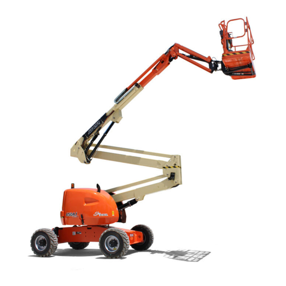
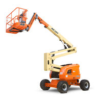
JLG 450A II Series Manuals
Manuals and User Guides for JLG 450A II Series. We have
3
JLG 450A II Series manuals available for free PDF download: Service And Maintenance Manual, Operation And Safety Manual
JLG 450A II Series Service And Maintenance Manual (396 pages)
Brand:
JLG
| Category:
Lifting Systems
| Size: 36.27 MB
Table of Contents
A General
3
Bhydraulic System Safety
3
Maintenance
3
Table of Contents
5
Specifications
17
Operating Specifications and Performance Data
17
1.1 Reach Specifications
17
1.2 Dimensional Data
17
1.3 Chassis
17
1.4 Capacities
17
1.5 Tires
18
1.6 Engine
18
1.8 Hydraulic Oil
19
1.9 Serial Number Location
20
Operator Maintenance and Lubrication Diagram
21
1.10 Operator Maintenance
22
Deutz Engine Dipstick Markings
24
Torque Chart (SAE Fasteners - Sheet 1 of 7)
26
Torque Chart (SAE Fasteners - Sheet 2 of 7)
27
Torque Chart (SAE Fasteners - Sheet 3 of 7)
28
Torque Chart (SAE Fasteners - Sheet 4 of 7)
29
Torque Chart (METRIC Fasteners - Sheet 5 of 7)
30
Torque Chart (METRIC Fasteners - Sheet 6 of 7)
31
Torque Chart (METRIC Fasteners - Sheet 7 of 7)
32
General
33
Machine Preparation, Inspection, and Maintenance
33
Preparation, Inspection, and Maintenance
33
Pre-Start Inspection
33
Pre-Delivery Inspection and Frequent Inspection
33
Annual Machine Inspection
33
Preventative Maintenance
33
Service and Guidelines
34
General
34
Safety and Workmanship
34
Cleanliness
34
Components Removal and Installation
34
Component Disassembly and Reassembly
35
Pressure-Fit Parts
35
Bearings
35
Gaskets
35
Battery
35
Bolt Usage and Torque Application
35
Hydraulic Lines and Electrical Wiring
35
Hydraulic System
35
Lubrication
35
Lubrication and Information
36
Hydraulic System
36
Hydraulic Oil
36
Changing Hydraulic Oil
36
Lubrication Specifications
36
Cylinder Drift Test
36
Platform Drift
36
Cylinder Drift
36
Pins and Composite Bearing Repair Guidelines
37
Welding on JLG Equipment
37
Do the Following When Welding on JLG Equipment
37
Do NOT Do the Following When Welding on JLG Equipment
37
Inspection and Preventive Maintenance Schedule
38
Chassis & Turntable
41
3.1 Tires and Wheels
41
Tire Inflation
41
Tire Damage
41
Tire Replacement
41
Wheel Replacement
41
Wheel Installation
42
3.2 Torque Hub
43
Oil Information
43
Roll and Leak Testing
43
Tightening and Torquing Bolts
43
Drive Hub and Brake Assembly (2WD and 4WD)
44
Drive Hub and Brake Assembly (2WD and 4WD) Parts List
45
Drive Hub (4WD Front Only)
46
Drive Hub (4WD Front Only) Parts List
47
MAIN DISASSEMBLY for "B" Drives
48
Hub-Spindle Disassembly
48
Cover Disassembly
49
Carrier Disassembly
49
Assemble Carrier
49
Cover Sub-Assembly
51
Hub-Spindle Sub-Assembly
52
Main Assembly
54
Cluster Gear Punch Marks
56
Tool List
59
3.3 Re-Align Torque Hub Input Coupling
60
Equipment Required
60
Procedure
60
3.4 Drive Motor
60
Description
60
Shaft Seal Replacement
61
Loop Flushing Valve
61
Troubleshooting
62
Disassembly
63
End Cap
64
Cylinder Kit
65
Swash Plate & Servo Piston
66
Inspection
67
Assembly
69
Swash Plate and Journal Bearing
70
Cylinder Kit Installation
71
End Cap
72
Initial Start-Up Procedures
73
Chassis Torque Values
74
3.5 Adjustment Procedure for Lockout Valve
75
Oscillating Axle Bleeding Procedure and Lockout Test
75
Lockout Cylinder Bleeding (Ram Cylinders)
75
Oscillating Axle Lockout Test
76
3.7 Swing Bearing
76
Description
76
Removal
76
Swing Bearing Installation
77
Disassembly
78
Swing Bearing Drive
79
Assembly
80
Installation
80
Swing Bearing (Dohi) Torque Sequence
81
Turntable Bearing Mounting Bolt Checks
82
Check Frame to Bearing Bolts
82
Check Turntable to Bearing Bolts
82
Wear Tolerance
82
3.8 Swing Motor
83
Preparation before Disassembly
83
Removal
84
Preparation before Disassembly
84
Swing Motor Removal and Installation
85
Disassembly and Inspection
86
Swing Motor - Exploded View
92
Assembly
93
One Piece Stator Assembly
99
Two Piece Stator Assembly
100
Final Checks
100
Installation
100
Auxiliary Pump
101
3.9 Generator
102
Every 250 Hours
102
Every 500 Hours
102
Overload Protection
102
Brushes and Slip Rings
102
Generator Brushes and Slip Rings
103
3.10 Deutz Engine
104
Check Oil Level
104
Change Engine Oil
104
Change Oil Filter
104
Replace Fuel Filter
105
Clean Fuel Strainer (D2011 L03 Only)
105
Deutz EMR 2
106
EMR 2 Engine Plug Pin Identification
111
EMR 2 Vehicle Plug Pin Identification
112
3.12 Bio Fuel in Deutz Engines
118
General
118
Bio Fuel
118
Biological Contamination in Fuels
119
3.13 Gm Engine General Maintenance
120
Drive Belt Maintenance
120
Engine Electrical System Maintenance
120
Checking/Filling Engine Oil Level
120
Change Engine Oil
121
Coolant Fill Procedure - Dual Fuel Engine
121
3.14 Gm Engine Dual Fuel System
122
Fuel Filter
122
GM 3.0 Dual Fuel System Components
123
Direct Electronic Pressure Regulator (DEPR)
124
Air Fuel Mixer
124
Electronic Throttle Control (ETC)
125
Electric Lock off
125
Engine Control Module (ECM)
125
Heated Exhaust Gas Oxygen Sensor
126
Gasoline Multi Point Fuel Injection System (MPFI)
126
Gasoline Fuel Pump
126
Gasoline Pressure and Temperature Sensor Manifold
126
Fuel Filter
127
Fuel Injector Rail
127
Fuel Injector
127
3.15 Gm Engine Fuel System Repair
127
Propane Fuel System Pressure Relief
127
Propane Fuel System Leak Test
127
Propane Fuel Filter Replacement
128
Direct Electronic Pressure Regulator (DEPR) Maintenance and Inspection
128
Check/Drain Oil Build-Up in 2-Stage Vaporizer
129
Air Fuel Mixer/Throttle Control Device Maintenance and Inspection
129
Exhaust System and Catalytic Converter Inspection and Maintenance
130
Temperature Manifold Absolute Pressure (TMAP) Sensor
130
Throttle Body (ETC) Replacement
130
Mixer Replacement
130
Electronic Pressure Regulator (EPR) Replacement
131
Regulator Replacement
131
Coolant Hose Replacement
131
Vapor Hose Replacement
131
Engine Control Module Replacement
132
Heated Exhaust Gas Oxygen Sensor Replacement
132
3.16 Gm Engine Lpg Fuel System Diagnosis
133
Fuel System Description
133
Diagnostic Aids
133
LPF Fuel System Diagnosis
134
Symptom Diagnosis
136
DTC to SPN/FMI Cross Reference Chart
144
GM 3.0L Engine - Sheet 1 of 2
146
GM 3.0L Engine - Sheet 2 of 2
147
DGC Diagnostic Support and Trouble Code Definitions
148
Section Layout
148
Fault Code Broadcast
150
Diagnostic Trouble Codes
150
Can
150
MIL Output
150
Diagnostic Calibration Configuration and Corrective Actions
150
Fault/Diagnostic Trouble Code Interaction
151
Faults Page with Active Fault Message
152
Faults Page with Historic Fault Message
153
DBW Diagnostic Test
154
Historic Fault Information Interface
155
Snapshot Data Interface
156
DTC 116- ECT Higher than Expected Stage 1
157
DTC 117- ECT/CHT Low Voltage
158
DTC 118- ECT/CHT High Voltage
160
DTC 122- TPS1 Signal Voltage Low
162
DTC 123- TPS1 Signal Voltage High
164
DTC 217- ECT Higher than Expected 2
166
DTC 219- RPM Higher than Max Allowed Governed Speed
167
DTC 336- Crank Signal Input Noise
168
DTC 337- Loss of Crank Input Signal
170
DTC 521- Oil Pressure Sender/Switch High Pressure
171
DTC 524- Oil Pressure Low
174
DTC 562- Battery Voltage (Vbat) Low
178
DTC 563- Battery Voltage (Vbat) High
180
DTC 601- Microprocessor Failure - FLASH
182
DTC 604- Microprocessor Failure - RAM
184
DTC 606- Microprocessor Failure - COP
186
DTC 642- 5 Volt External Low Voltage
188
DTC 643- 5 Volt External High Voltage
189
DTC 1612- Microprocessor Failure - RTI 1
190
DTC 1613- Microprocessor Failure - RTI 2
191
DTC 1614- Microprocessor Failure - RTI 3
193
DTC 1615- Microprocessor Failure - A/D
195
DTC 1616- Microprocessor Failure - Interrupt
197
DTC 1625- CAN J1939 Shutdown Request
199
DTC 1626- CAN J1939 Transmit (Tx) Fault
200
DTC 1627- CAN J1939 Receive (Rx) Fault
201
DTC 1628- CAN Address Conflict Failure
202
DTC 1629- J1939 TSC1 Message Receipt Loss
204
DTC 1652- TPS1 Loss of Communications
205
DTC 2111- Unable to Reach Lower TPS
206
DTC 2112- Unable to Reach Higher TPS
208
DTC 9999- Throttle Actuator Failsafe Spring Failure
209
DTC to SPN/FMI Table
210
Exhaust Venturi Adjustment
211
Counterweight Installation
212
Boom & Platform
213
4.1 Boom Maintenance
213
Remove Boom Assembly
213
Main Boom Disassembly
214
Inspection
214
Main Boom Assembly
215
Install Boom Assembly
215
Boom Assembly
216
Boom Limit Switches
217
Main Boom
218
4.2 Rotary Actuator
219
Theory of Operation
219
Required Tools
219
Rotary Actuator - Exploded View
220
Disassembly
221
Inspection
224
Assembly
225
Installing Counterbalance Valve
230
Platform Support Torque Values
231
4.3 Powertrack Maintenance
232
Remove Link
232
Install New Link
235
Replace Fixed End Brackets
238
Replace Moving End Brackets
239
Hydraulics
241
O-Ring Lubrication
241
Cup and Brush
241
Dip
242
Spray
242
Brush-On
242
Hydraulic Cylinders
243
Tower Lift Cylinder
244
Tower Lift Cylinder
245
Tapered Bushing Removal
246
Rod Seal Installation
247
Tapered Bushing Installation
248
Main Lift Cylinder
249
Main Lift Cylinder
250
Composite Bushing Installation
251
Rod Seal Installation
252
Master Cylinder (450 A/AJ) Without Arctic Package
253
Master Cylinder (450A)
254
Master Cylinder (450AJ W/O Arctic Package)
255
Composite Bushing Installation
256
Installation of Head Seal Kit
257
Master Cylinder (450 A/AJ) with Arctic Package
258
Master Cylinder (450AJ W/Arctic Package)
259
Tapered Bushing Removal
260
Rod Seal Installation
261
Tapered Bushing Installation
262
Telescope Cylinder
263
Telescope Cylinder 450A/AJ
264
Composite Bushing Installation
265
Rod Seal Installation
266
Slave (Platform Level) Cylinder Without Arctic Pkg
267
Platform Level Slave Cylinder Assembly (450A)
268
Platform Level Slave Cylinder Assembly (450AJ W/O Arctic Package)
269
Composite Bushing Installation
270
Installation of Head Seal Kit
271
Platform Level (Slave) Cylinder with Arctic Package
272
Platform Level Slave Cylinder Assembly (450AJ W/Arctic Package)
273
Tapered Bushing Removal
274
Rod Seal Installation
275
Tapered Bushing Installation
276
Jib Lift Cylinder (AJ Only) Without Arctic Package
277
Jib Lift Cylinder (450AJ W/O Arctic Package)
278
Composite Bushing Installation
279
Rod Seal Installation
280
Cylinder Head Installation
281
Jib Lift Cylinder (AJ Only) with Arctic Package
282
Jib Lift Cylinder (450AJ W/Arctic Package)
283
Tapered Bushing Removal
284
Rod Seal Installation
285
Tapered Bushing Installation
286
Steer Cylinder
287
Steer Cylinder Assembly
288
Piston Seal and Wear Ring
289
Cylinder Head Assembly
290
Axle Lockout Cylinder
291
Axle Lockout Cylinder
292
Hydraulic Pump (Gear)
293
Disassembly
293
Inspect Parts for Wear
295
General Information
296
Reverse Shaft Rotation of Pump
296
Assembly
296
Hydraulic Pump Bolt Torque Chart
298
Placing Pump Back into Service
299
Variable Pump
299
Ports and Pressure Gauges
299
NFPE Control
299
Remove and Install FNR and NFPE Modules
300
Remove and Install FNR and NFPE Control Orifices
300
Charge Relief Valve
300
Gauge Port Locations
301
Plugs/Fittings Size & Torque
302
Shaft Seal and Shaft Replacement
303
Shaft Components
304
Charge Pump
305
Hydraulic Component Start-Up
306
Main Valve Block Pressure Setting Procedures
307
Telescope
307
Main Relief
307
Steer
307
Lift down
307
Swing
307
Platform Valve Block Pressure Setting Procedures
307
Platform Level Extend
307
Platform Level Retract
307
Articulating Jib (AJ Only)
307
Main Control Valve
308
Platform Control Valves
309
Jlg Control System
311
6.1 Introduction
311
Controller Block Diagram
312
Connect JLG Control System Analyzer
313
Using Analyzer
313
Changing Access Level
314
Adjust Parameters
315
Machine Setup
316
Level Vehicle Description
316
Revision
317
Analyzer Software Version 6.8 - Sheet 1 of 6
319
Analyzer Software Version 6.8 - Sheet 2 of 6
320
Analyzer Software Version 6.8 - Sheet 3 of 6
321
Analyzer Software Version 6.8 - Sheet 4 of 6
322
Analyzer Software Version 6.8 - Sheet 5 of 6
323
Analyzer Software Version 6.8 - Sheet 6 of 6
324
Personality Ranges/Defaults
325
Machine Configuration Programming Information Software Version P6.1 to Present
328
System Test
336
Test from Platform
336
Test from Ground Station
338
System Test Messages
340
Fault Codes
343
Control Module and Fault Code Light Locations
350
Help Fault Codes, Displayed Faults, and Descriptions
351
Basic Electrical Information & Schematics
371
General
371
7.2 Multimeter Basics
371
Grounding
371
Backprobing
371
Min/Max
371
Polarity
371
Scale
371
Voltage Measurement
371
Resistance Measurement
372
Continuity Measurement
372
Current Measurement
373
Applying Silicone Dielectric Compound to Electrical Connections
373
Dielectric Grease Application
374
Deutsch HD, DT, DTM, DRC Series
374
AMP Seal
374
AMP Mate-N-Lok
375
DIN Connectors
375
Exclusions
375
7.4 Amp Connector
376
Contact Assembly
376
Connector Assembly
376
Disassembly
377
Wedge Lock
377
Service - Voltage Reading
377
7.5 Deutsch Connectors
378
DT/DTP Series Assembly
378
DT/DTP Series Disassembly
378
HD30/HDP20 Series Assembly
379
HD30/HDP20 Series Disassembly
379
Electrical Components 1 of 2
380
Electrical Components 2 of 2
381
Chassis/Platform Electrical Schematic - Sheet 1 of 2
382
Chassis/Platform Electrical Schematic -Sheet 2 of 2
383
Deutz Engine Electrical Schematic
384
GM 3.0L Engine/Chassis Electrical Schematic
385
ECM Electrical Schematic - Sheet 1 of 2
386
ECM Electrical Schematic - Sheet 2 of 2
387
Main Hydraulic Schematic - 1 of 2
388
Main Hydraulic Schematic - 2 of 2
389
Two Wheel Drive Hydraulic Schematic - 1 of 2
390
Two Wheel Drive Hydraulic Schematic - 2 of 2
391
Four Wheel Drive Hydraulic Schematic - 1 of 2
392
Four Wheel Drive Hydraulic Schematic - 2 of 2
393
Advertisement
JLG 450A II Series Operation And Safety Manual (112 pages)
Brand:
JLG
| Category:
Boom Lifts
| Size: 3.63 MB
Table of Contents
Table of Contents
7
Section - Paragraph, Subject
12
Section - Paragraph, Subject Page
13
Section 1. Safety Precautions
13
General
13
Pre-Operation
13
Operator Training and Knowledge
13
Workplace Inspection
14
Machine Inspection
14
Operation
15
General
15
Trip and Fall Hazards
15
Electrocution Hazards
16
Minimum Approach Distances (M.A.D.)
17
Tipping Hazards
18
Crushing and Collision Hazards
19
Towing, Lifting, and Hauling
20
Additional Hazards / Safety
21
Section 2. User Responsibilities, Machine Preparation, and Inspection
23
2.1 Personnel Training
23
Operator Training
23
Training Supervision
23
Operator Responsibility
23
Preparation, Inspection, and Maintenance
24
Inspection and Maintenance Table
25
Pre-Start Inspection
26
Function Check
27
Basic Nomenclature - Sheet 1 of 2
28
Basic Nomenclature - Sheet 2 of 2
29
Daily Walk-Around Inspection - Sheet 1 of 3
30
General
31
Daily Walk-Around Inspection - Sheet 3 of 3
32
Oscillating Axle Lockout Test (if Equipped)
33
Section 3. Machine Controls and Indicators
35
3.1 General
35
3.2 Controls and Indicators
35
Ground Control Station
35
Ground Control Station - a Models
36
Ground Control Station - AJ Models
37
Ground Control Indicator Panel
39
Ground Control Indicator Panel
40
Platform Control Station
42
Platform Control Console
43
Platform Control Indicator Panel
45
Platform Control Indicator Panel - Sheet 1 of
47
Platform Control Indicator Panel - Sheet 2 of
48
Section 4. Machine Operation
49
Description
49
Operating Characteristics and Limitations
49
Capacities
49
Stability
50
Engine Operation
50
Starting Procedure
50
Shutdown Procedure
51
Position of Least Forward Stability
52
Traveling (Driving)
53
Position of Least Backward Stability
53
Grade and Side Slopes
54
Traveling Forward and Reverse
55
Steering
55
Platform
55
Platform Level Adjustment
55
Platform Rotation
55
Boom
55
Swinging the Boom
56
Raising and Lowering the Lower and MID Boom
56
Raising and Lowering the Main (Upper) Boom
56
Telescoping the Main Boom
56
Function Speed Control
56
Auxiliary Pump
56
Oscillating Axle Lockout Test (if Equipped)
57
4.11 Shut down and Park
57
4.12 Lifting and Tie down
58
Lifting
58
Tie down
58
Lifting and Tie down Chart
59
4.13 Towing
60
Prior to Towing
60
Drive Disconnect Hub
60
Dual Fuel System (Gas Engine Only)
61
Changing from Gasoline to LP Gas
61
Changing from LP Gas to Gasoline
61
Decal Installation - Sheet 1 of 6
62
Decal Installation - Sheet 2 of 6
63
Decal Installation - Sheet 3 of 6
64
Decal Installation - Sheet 4 of 6
65
Decal Installation - Sheet 5 of 6
66
Decal Installation - Sheet 6 of 6
67
Section 5. Emergency Procedures
71
General
71
Incident Notification
71
Emergency Operation
72
Operator Unable to Control Machine
72
Platform or Boom Caught Overhead
72
Emergency Towing Procedures
72
Section 6. General Specifications & Operator Maintenance
73
Introduction
73
Operating Specifications and Performance Data
73
Operating Specifications - 450A/450AJ
73
Reach Specifications
74
Operating Specifications - 510AJ
74
Dimensional Data
75
Chassis
75
Capacities
76
Tires
76
Engine
77
Deutz F3M1011F
77
Deutz F3M2011F
78
Major Component Weights
79
Gm 3.0L
79
Hydraulic Oil
80
Mobil DTE 13M Specs
81
Mobil EAL H 46 Specs
82
Serial Number Location
83
Serial Number Locations
83
Engine Operating Temperature Specifications
84
Engine Operating Temperature Specifications
85
Engine Operating Temperature Specifications
86
Engine Operating Temperature Specifications
87
Engine Operating Temperature Specifications
88
Engine Operating Temperature Specifications
89
Engine Operating Temperature Specifications
90
Engine Operating Temperature Specifications
91
Operator Maintenance and Lubrication Diagram
92
Operator Maintenance
93
Tires & Wheels
102
Tire Inflation
102
Tire Damage
102
Tire Replacement
102
Wheel Replacement
103
Wheel Installation
103
Wheel Torque Chart
104
Section - Paragraph, Subject Page
105
Draining Oil Build up from the Propane Regulator
105
Propane Fuel Filter Replacement
106
Removal
107
Installation
107
Propane Fuel System Pressure Relief
108
Section 7 - Inspection and Repair Log
109
Inspection and Repair Log
110
JLG 450A II Series Operation And Safety Manual (134 pages)
Brand:
JLG
| Category:
Boom Lifts
| Size: 4.03 MB
Table of Contents
Revision Log
6
Table of Contents
7
Section 1 - Safety Precautions
15
General
15
Pre-Operation
15
Operator Training and Knowledge
15
Workplace Inspection
16
Machine Inspection
17
Operation
17
General
17
Trip and Fall Hazards
18
Electrocution Hazards
19
Tipping Hazards
21
Crushing and Collision Hazards
24
Towing, Lifting, and Hauling
25
Maintenance
25
Maintenance Hazards
25
Battery Hazards
27
Section - 2 - User Responsibilities, Machine Preparation
29
Personnel Training
29
Operator Training
29
Training Supervision
29
Operator Responsibility
29
Preparation, Inspection, and Maintenance
30
Pre-Start Inspection
32
Function Check
33
Skyguard Function Test
34
General
38
Oscillating Axle Lockout Test (if Equipped)
40
Section 3 - Machine Controls and Indicators
41
General
41
Controls and Indicators
41
Ground Control Station
42
Jib Lift
46
Engine Start/Auxiliary Power/Function Enable
46
Power/Emergency Stop
47
Platform/Ground Select
47
Hourmeter
47
Ground Control Indicator Panel
48
Tower Boom Lift
48
Main Boom Lift
48
Platform Control Station
51
Platform Control Indicator Panel
55
Section 4 - Machine Operation
61
Description
61
Operating Characteristics and Limitations
61
Capacities
61
Stability
62
Engine Operation
62
Starting Procedure
62
Shutdown Procedure
63
Fuel Reserve / Shut-Off System
64
Telescope
65
Traveling (Driving)
66
Traveling Forward and Reverse
67
Steering
69
Platform
69
Platform Level Adjustment
69
Platform Rotation
69
Boom
69
Swinging the Boom
70
Raising and Lowering the Tower Boom
70
Raising and Lowering the Main Boom
70
Telescoping the Main Boom
70
Function Speed Control
70
Machine Safety System Override (Msso)
71
Skyguard Operation
71
Auxiliary Pump
72
Oscillating Axle Lockout Test (if Equipped)
72
Shut down and Park
73
Lifting and Tie down
73
Lifting
73
Tie down
73
Towing
75
Prior to Towing
75
Dual Fuel System (Gas Engine Only)
76
Changing from Gasoline to LP Gas
76
Changing from LP Gas to Gasoline
76
Section 5 - Emergency Procedures
87
General
87
Incident Notification
87
Emergency Operation
88
Operator Unable to Control Machine
88
Platform or Boom Caught Overhead
88
Emergency Towing Procedures
88
Section 6 - General Specifications and Operator Maintenance
89
Introduction
89
Operating Specifications and Performance
89
Data
89
Reach Specifications
90
Dimensional Data
91
Chassis
91
Major Component Weights
92
Capacities
92
Tires
92
Engine
93
Hydraulic Oil
95
Serial Number Location
99
Specifications
102
Operator Maintenance
109
Tires & Wheels
122
Tire Inflation
122
Tire Damage
122
Tire Replacement
122
Wheel and Tire Replacement
123
Wheel Installation
123
Propane Fuel Filter Replacement
125
Removal
125
Installation
126
Propane Fuel System Pressure Relief
126
Supplemental Information
127
Advertisement
Advertisement
Related Products
JLG 450AJ II Series
JLG 450A
JLG 450AJ
JLG 40H+6
JLG 40H
JLG 4007
JLG 4008
JLG 4013
JLG 4012
JLG 40HA
JLG Categories
Boom Lifts
Lifting Systems
Scissor Lifts
Construction Equipment
Forklifts
More JLG Manuals
Login
Sign In
OR
Sign in with Facebook
Sign in with Google
Upload manual
Upload from disk
Upload from URL