
Related Manuals for Piazzetta M360 Q


Summary of Contents for Piazzetta M360 Q
- Page 1 Monoblocco Firebox M360 Q ISTRUZIONI PER L’INSTALLAZIONE, L’USO E LA MANUTENZIONE INSTRUCTION FOR INSTALLATION, USE AND MAINTENANCE H07030250 / DT2001306-02...
- Page 2 Gentile Cliente, La ringraziamo per aver preferito uno dei nostri prodotti, frutto di lunga esperienza e di una continua ricerca per un prodotto superiore in termini di sicurezza, affidabilità e prestazioni. In questo manuale troverà tutte le informazioni ed i consigli utili per poter utilizzare il suo prodotto nel massimo della sicurezza ed efficienza.
-
Page 3: Table Of Contents
INDICE DT2010187-00 Capitolo Titolo Pagina NORME GENERALI Camino o canna fumaria singola Ispezione per raccolta fuliggine Comignolo Presa d’aria esterna Ambiente di installazione Portata del solaio e pavimento ed isolamento Capacità di riscaldamento Isolanti termici idonei Distanze minime di sicurezza 1.10 Prevenzione degli incendi domestici CARATTERISTICHE E DATI TECNICI Descrizione dell’apparecchio... -
Page 4: Norme Generali
1.0 NORME GENERALI DT2012215-00 Prima di procedere con l’installazione scegliere la posizione più adatta all’installazione del vostro caminetto in base alle prescrizioni indicate al paragrafo “DISTANZE MINIME DI SICUREZZA” ed a tutte le voci sotto elencate. Fig. 1 COMIGNOLO CANALE DA FUMO VERIFICA PORTATA SOLAIO COLLEGAMENTO ALLA CANNA FUMARIA... -
Page 5: Camino O Canna Fumaria Singola
Se la canna fumaria dovesse essere male dimensionata o installata DT2030258-00 nella inosservanza di quanto citato sopra, il Gruppo Piazzetta S.p.A. declina ogni responsabilità ad un cattivo funzionamento Fig. 3 Fig. 4 del prodotto o al danneggiamento di cose, persone o animali. -
Page 6: Comignolo
DT2010025-03 1.3 COMIGNOLO Il comignolo è un dispositivo posizionato sulla sommità del camino, atto a Fig. 7 Fig. 8 facilitare la dispersione in atmosfera dei prodotti della combustione. Il comignolo dovrà rispondere ai seguenti requisiti: - avere sezione e forma interna equivalente a quella del camino (A); - avere sezione utile di uscita (B) non minore del doppio di quella del camino (A);... -
Page 7: Presa D'aria Esterna
DT2012216-00 1.4 PRESA D’ARIA ESTERNA Il caminetto, per un regolare funzionamento, deve poter disporre dell’aria Fig. 12 necessaria alla combustione mediante presa d’aria esterna. La presa d’aria deve: - avere una sezione libera totale di dimensioni pari o superiore al dato Interruttore riportato al paragrafo “DATI TECNICI”;... -
Page 8: Capacità Di Riscaldamento
DT2010130-01 1.7 CAPACITÀ DI RISCALDAMENTO Verificare la capacità di riscaldamento dell’apparecchio confrontando la potenza nominale riportata al paragrafo “DATI TECNICI” e la potenza richiesta dagli ambienti da riscaldare. Il calcolo approssimativo del fabbisogno energetico si ottiene moltiplicando i metri quadrati per l’altezza del soffitto, il risultato viene moltiplicato per un coefficiente che dipende dal grado di isolamento del fabbricato, ovvero, da fattori interni e fattori esterni della abitazione: a) Fattori interni: tipologia di serramenti, spessore degli isolamenti e delle pareti, tipologia di materiali costruttivi, presenza di vani scale, pareti con ampie vetrate, soffitti elevati, ubicazione del volume da riscaldare rispetto ad altri volumi adiacenti riscaldati o non riscaldati, …... -
Page 9: Prevenzione Degli Incendi Domestici
DT2010027-02 1.10 PREVENZIONE DEGLI INCENDI DOMESTICI L’installazione e l’utilizzo del prodotto deve essere fatta in conformità con le istruzioni del fabbricante, e nel rispetto delle normative europee, nazionali e dei regolamenti locali. Quando un tubo di scarico fumi passa attraverso ad una parete o ad un soffitto è necessario applicare modalità di installazioni particolari (protezione, isolamento termico, distanze da materiali sensibili al calore, ecc...). -
Page 10: Caratteristiche E Dati Tecnici
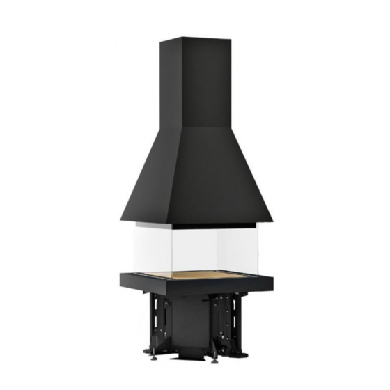
2.1 DESCRIZIONE DELL’APPARECCHIO Il monoblocco estetico M360 Q rappresenta la soluzione ideale per chi ricerca forme inedite del caminetto. L’ampia vetratura, una facciata focolare lineare e pulita, danno una visione del fuoco senza paragoni. L’aria comburente si autoregola e garantisce una buona pulizia del vetro a 360°. -
Page 11: Accessori E Dotazioni
DT2012222-01 2.2 ACCESSORI E DOTAZIONI Descrizione Accessori Paralegna Dotazione Cassetto cenere Dotazione Maniglia registro fumi Dotazione Guanto Dotazione Piano fuoco Dotazione Griglia presa aria 175x325 Dotazione Griglia per piano verniciata Dotazione Deflettore fumi Dotazione Punta da trapano Ø 5,25 mm Dotazione DT2012223-00 2.3 CARATTERISTICHE... -
Page 12: Dati Tecnici
DT2012795-02 2.5 DATI TECNICI Modello M360Q closed doors Modello M360Q open doors Prodotto-tipo Prodotto-tipo M360Q CLOSED DOORS M360Q OPEN DOORS alla potenza alla potenza Descrizione Descrizione Unità di misura Unità di misura nominale nominale Combustibile Combustibile legna (N.B.) legna (N.B.) Potenza termica Potenza termica 16,4... -
Page 13: Dimensioni
DT2034473-00 2.6 DIMENSIONI Dimensioni in cm. * = ingombri del rivestimento. Fig. 18 H07030250 / DT2001306-02... -
Page 14: Schema Elettrico
DT2033227-01 2.7 SCHEMA ELETTRICO Fig. 19 CONN EST F7 + F8 CHIUSI CONN INT MOLM MOLF FUS1 F10 F1 F2 POS. CONNESSIONI ESTERNE CENTRALINA POS. CONNESSIONI ESTERNE CENTRALINA RIF. LEGENDA COLORI Motore 1 Messa a terra (massa) F1 Nero Motore 2 PM1 Pulsante di comando motore 1 F2 Rosso SA1 Sensore chiusura motore 1 N/C... -
Page 15: Preliminari All'installazione
Il prodotto va sollevato nei punti d’aggancio indicati. Non afferrarlo dai telai vetro ancora abbassati. Il Gruppo Piazzetta S.p.A. diniega ogni responsabilità seguita ad un possibile malfunzionamento, danno riportato a cose e/o persone, dovuto ad un incorretto disimballo, uso ed installazione del prodotto. -
Page 16: Installazione
4.0 INSTALLAZIONE DT2012228-00 DT2012229-01 4.1 CONNESSIONE ALLA RETE ELETTRICA Sotto al basamento è collocata la centralina (A): è necessario vi sia già stata Fig. 22 predisposta una risalita del cavo d’alimentazione per la connessione del prodotto alla rete elettrica (230V). Per norma di legge l’impianto deve essere previsto di messa a terra. -
Page 17: Posizionamento Monoblocco
Il prodotto va sollevato nei punti d’aggancio indicati. Non afferrarlo dai telai vetro ancora abbassati. Il Gruppo Piazzetta S.p.A. diniega ogni responsabilità seguita ad un possibile malfunzionamento, danno riportato a cose e/o persone, dovuto ad un incorretto uso ed installazione del prodotto. - Page 18 Nel caso ci siano delle differenze, controllare la messa in bolla della cappa e Fig. 28 del basamento [A] e correggere il centraggio del prodotto distribuendo con equidistanza il margine tra vetro (Q) e deflettore (R). (Fig. 28) Se il basamento è centrato rispetto alla cappa, il prodotto funziona al meglio delle proprie prestazioni e i vetri si sporcano meno.
-
Page 19: Posizionamento Copribordo
DT2012322-00 4.4 POSIZIONAMENTO COPRIBORDO Liberare il cavo (A) con fissati i pulsanti i comando (B), recidendo la fascetta Fig. 31 che lo tiene bloccato alla centralina (C), all’interno del basamento. I pulsanti di comando (B) dovranno essere installati in corrispondenza dei due fori (F) ricavati sul profilo copribordo (D). -
Page 20: Uso
5.0 USO DT2012235-00 Alcune importanti nozioni possono essere determinanti per la buona resa di funzionamento del vostro prodotto, di seguito citiamo alcune nozioni per utilizzarlo al meglio cercando di esservi di aiuto sulla scelta della legna da ardere, sulla regolazione dei registri, e per un regolare utilizzo dell’apparecchio. Durante il funzionamento, alcune parti del prodotto (porta, maniglia, registri, rivestimento) possono raggiungere temperature elevate. -
Page 21: Regolazione Registro Fumi
DT2033199-00 Terminata la carica, chiudere il vetro e riportare manulmente il registro nella Il Gruppo Piazzetta S.p.A. diniega ogni responsabilità seguita ad un posizione di funzionamento evitando di lasciare la maniglia di regolazione possibile malfunzionamento, danno riportato a cose e/o persone, dovuto agganciata alla cappa: è... -
Page 22: Accensione
(C.A.T. Centro Assistenza - interrompere immediatamente l’alimentazione; Tecnica Piazzetta). - non aprire i vetri del focolare; In caso di incendio spegnere il fuoco mediante estintore. - chiudere il registro fumi (posizione MINIMA). -
Page 23: Manutenzione
In riferimento alle normative vigenti sulla sicurezza degli apparecchi elettrici, per tutte le operazioni di installazione manutenzione o di intervento che comportino l’accesso all’interno del rivestimento o della camera fumi, è obbligatorio rivolgersi ad un Centro Assistenza Tecnica del Gruppo Piazzetta o a personale qualificato. -
Page 24: Pulizia Del Cassetto Cenere (Giornaliera)
DT2010063-00 6.5 PULIZIA DEL CASSETTO CENERE La pulizia del focolare e del cassetto cenere deve essere giornaliera. L’utilizzo del focolare per una intera giornata contribuisce all’accumulo di cenere o residui della combustione. La non curanza di questo comporta un eccesso di residui dell’apparecchio, che andranno ad aggravare il buon funzionamento del prodotto. Anche il cassetto cenere necessita di tale cura, se dovesse riempirsi o ad andare ad ostruire la griglia del focolare, avremo un inadeguato funzionamento del prodotto. -
Page 25: Principali Anomalie
Questo libretto di istruzioni contiene tutte le informazioni utili per l’installazione, l’uso e la manutenzione. Chiamare il centro assistenza del Gruppo Piazzetta S.p.A. solo dopo avere accuratamente consultato le istruzioni. Problema Causa Soluzione Aprire il registro fumi. - Page 26 Problema Causa Soluzione Usare la quantità di legna indicata Quantità di legna inferiore a quella nelle istruzioni (vedi paragrafo DATI Il focolare non scalda necessaria per ottenere la resa TECNICI) nominale Focolare sottodimensionato per Integrarlo con un’altra fonte di l’ambiente da riscaldare riscaldamento Isolamento non adeguato dell’...
- Page 27 In relazione alle norme vigenti sulla sicurezza degli apparecchi elettrici, per tutte le operazioni di installazione, manutenzione o intervento che comportano l’accesso a parti elettriche è obbligatorio rivolgersi ad un Centro Assistenza Tecnica Piazzetta o a personale qualificato. H07030250 / DT2001306-02...
-
Page 28: Important Information
In line with its policy of constant product improvement and renewal, the manufacturer may make changes without notice. This document is the property of Gruppo Piazzetta S.p.A.; no part of it may be disclosed to third parties without the written permission of Gruppo Piazzetta S.p.A. - Page 29 CONTENTS DT2010187-00 Section Heading Page GENERAL RULES Single chimney or flueway Soot inspection Chimney stack Fresh air intake Installation enviroment Load-bearing capacity of the floor and the roof Heating capacity Suitable heat insulating materials Minimum safety distances 1.10 Prevention of domestic fires TECHNICAL DATA AND SPECIFICATIONS Description of the appliance Accessories and equipment...
-
Page 30: General Rules
1.0 GENERAL RULES DT2012215-00 Before proceeding with installation, choose the most suitable position for your fireplace according to the indications given in the paragraph “MINIMUM SAFETY DISTANCES” and to all the indications below. Fig. 1 COMIGNOLO CHIMNEY STACK CANALE DA FUMO FLUEWAY CHECK OF FLOOR VERIFICA PORTATA SOLAIO... -
Page 31: Single Chimney Or Flueway
If the flue pipe is an incorrect size or installed other than in compliance with the above instructions, Gruppo Piazzetta S.p.A. cannot be held liable for malfunctioning of the product, damage to property or injury to persons or animals. -
Page 32: Chimney Stack
DT2010025-03 1.3 CHIMNEY STACK Fig. 7 Fig. 8 The chimney stack must comply with the following requirements: - it must have an internal section and shape the same as the flue (A); - it must have a useful outlet section (B) of not less than twice that of the flue (A);... -
Page 33: Fresh Air Intake
DT2012216-00 1.4 FRESH AIR INTAKE To ensure trouble-free operation the fireplace must have the necessary air Fig. 12 available for combustion and this is provided through the fresh air intake. The fresh air intake must: - have a total free cross section at least equal to the size given in the External Interruttore paragraph “TECHNICAL DATA”;... -
Page 34: Heating Capacity
DT2010130-01 1.7 HEATING CAPACITY Check the heating capacity of the appliance by comparing the rated power given in the paragraph “TECHNICAL DATA” with the power required by the environment to be heated. The energy requirement may be calculated approximately by multiplying the square metres of area by the height of the ceiling; the result is then multiplied by a coefficient, which depends on the degree of insulation of the building, that is, on internal and external factors of the dwelling: a) Internal factors: type of window and door frames, thickness of the insulation and walls, type of building materials, presence of stairwells, walls with extensive glazing, high ceilings, position of the rooms to be heated in relation to other adjacent heated or unheated rooms, …... -
Page 35: Prevention Of Domestic Fires
DT2010027-02 1.10 PREVENTION OF DOMESTIC FIRES The product must be installed and used in compliance with the manufacturer’s instructions and European and national standards as well as local regulations. When a flue pipe passes through a wall or a ceiling, special installation methods must be applied (protection, thermal insulation, distances from heat-sensitive materials, etc.). -
Page 36: Technical Data And Specifications
2.1 DESCRIPTION OF THE APPLIANCE The highly original stove M360 Q is ideal for anyone seeking an unusual form of fireplace. The extensive glazed surface and a clean-cut, linear front to the firebox offer an unparalleled view of the fire. The combustion air is self-regulating and ensures that the glass remains clean all the way round. -
Page 37: Accessories And Equipment
DT2012222-01 2.2 ACCESSORIES AND EQUIPMENT Pipe cover Optional Fireguard In kit Ash drawer In kit Removable handle for smoke damper In kit Glove In kit Grate In kit Air intake grille 175x325 In kit Grille for enamelled plate In kit Smoke baffle plate In kit Drill bit Ø... -
Page 38: Technical Data
DT2012795-02 2.5 TECHNICAL DATA Model M360Q closed doors Model M360Q open doors Product type Product type M360Q CLOSED DOORS M360Q OPEN DOORS Unit of at rated Unit of at rated Description Description measurement power measurement power Fuel Fuel wood (N.B.) wood (N.B.) Thermal power Thermal power... -
Page 39: Dimensions
DT2034473-00 2.6 DIMENSIONS Measurements in cm. * = Cladding area. Fig. 18 H07030250 / DT2001306-02... -
Page 40: Wiring Diagram
DT2033227-01 2.7 WIRING DIAGRAM Fig. 19 CONN EST SWITCH F7 + F8 CLOSED ON CHIUSI F7-F8 CONN INT MOLM MOLF FUS1 F10 F1 F2 POS. CONTROL UNIT EXTERNAL CONNECTIONS POS. CONTROL UNIT EXTERNAL CONNECTIONS RIF. KEY TO COLOURS Motor 1 Earth (ground) F1 Black Motor 2... -
Page 41: Preparation For Installing
Do not hold the product by the glass frames that are still in a lowered position. Gruppo Piazzetta S.p.A. cannot be held responsible for any possible malfunction, damage to property or injury to persons due to incorrect unpacking, use or installation of the product. -
Page 42: Installation
4.0 INSTALLATION DT2012228-00 DT2012229-01 4.1 CONNECTING THE BASE TO THE MAINS ELECTRICITY SUPPLY The control unit (A) is positioned on the basement. There have to be prepared Fig. 22 the connection cables in order for the product to be connected to the mains electricity supply (230V). -
Page 43: Positioning The Appliance
Gruppo Piazzetta S.p.A. cannot be held responsible for any possible malfunction, damage to property or injury to persons due to incorrect use or installation of the product. - Page 44 If there is any difference, check that the hood and the base [A] are level and Fig. 28 adjust the position of the product to centre it, distributing the margin between glass (Q) and plate (R) so that the distances are equal. (Fig. 28) If the base is centred in relation to the hood, product operation and performance is at its best and the glass becomes less dirty.
-
Page 45: Positioning The Edging Trim
DT2012322-00 4.4 POSITIONING THE EDGING TRIM Free the cable (A) with the control buttons (B) fastened to it, by cutting the band that secures it to the control unit (C) inside the base. The control buttons (B) must be installed where the two holes (F) have been made on the edging trim (D). -
Page 46: Use
5.0 USE DT2012235-00 Certain basic facts can be all-important for best performance and getting the most out of your appliance. Please find below some basic information intended to be of use with regard to the choice of firewood, the adjustment of the dampers and proper operation of the appliance. During operation, some parts of the appliance (door, handle, dampers, surround) can reach high temperatures. -
Page 47: Smoke Damper Regulation
The most suitable position for the smoke damper will be found with experience. Gruppo Piazzetta S.p.A. cannot be held responsible for any possible malfunction, damage to property or injury to persons due to incorrect use or DT2033199-0 installation of the product. -
Page 48: Lighting
In the event of overheating or if some appliance parts of the flue turn red: When the appliance has cooled down, find the cause of the problem and - immediately stop the supply of fuel; if necessary call in specialised personnel (C.A.T. – Piazzetta After-Sales - do not open the fireplace door; Service Centre). -
Page 49: Maintenance
DT2012240-00 In compliance with current safety laws for electrical appliances, it is compulsory to contact a Gruppo Piazzetta After-Sales Service Centre or qualified personnel for all work involving installation, maintenance or servicing/repair which involves access to the inside of the cladding or the smoke chamber. -
Page 50: Cleaning The Ash Tray (Daily)
DT2010063-00 6.5 CLEANING THE ASH TRAY (DAILY) The grate and the ash tray must be cleaned daily. Using the grate for a whole day contributes to the accumulation of ash or residual combustion products. If cleaning is not done regularly there will be an excess of residues, which will affect appliance efficiency. The ash tray also needs emptying regularly, because if it fills up and obstructs the grate grid it will cause appliance malfunction. -
Page 51: Troubleshooting
The manufacturer shall not be liable for any problems caused by lack of or inefficient maintenance or by failure to comply with the instructions in the product installation and operating guide. This instruction booklet contains all the useful information for installation, operation and maintenance. Only call the Gruppo Piazzetta S.p.A. service centre after having scrupulously followed all the instructions. - Page 52 Problem Cause Remedy Use the quantity of wood indicated Quantity of wood less than in the instructions (see “TECHNICAL The fire box does not heat necessary for nominal efficiency DATA” paragraph) Undersized grate for the Integrate with another product environment to be heated Inadequate insulation for the environment in which the fireplace Insulate well with suitable materials...
- Page 53 Pursuant to current regulations on the safety of electrical equipment, you must contact a Piazzetta After-Sales Service Centre or a qualified electrician for all and any work connected with installation, maintenance or servicing that involves access to electrical parts.
- Page 54 H07030250 / DT2001306-02...
- Page 55 H07030250 / DT2001306-02...
- Page 56 N° matricola prodotto da comunicare al Centro Assistenza Tecnica del Gruppo Piazzetta in caso di richiesta assistenza. Product serial number, to be quoted when requesting service from the Gruppo Piazzetta After-Sales Service Centre. Via Montello, 22 31011 Casella d’Asolo (TV) - ITALY Tel.
Need help?
Do you have a question about the M360 Q and is the answer not in the manual?
Questions and answers