Table of Contents
Advertisement
Quick Links
Advertisement
Table of Contents

Subscribe to Our Youtube Channel
Related Manuals for Piazzetta M 360


Summary of Contents for Piazzetta M 360
- Page 1 M 360 Firebox INSTRUCTION FOR INSTALLATION, USE AND MAINTENANCE M360 Firebox Installation Instructions Robeys Ltd, Riverside, Goods Road, Belper, Derbyshire, England. DE56 1UU February 2015 Tel 01773 820940 Fax 01773 820477 Email info@robeys.co.uk www.robeys.co.uk...
- Page 2 M360 Firebox Installation Instructions February 2015...
-
Page 3: Important Information
In line with its policy of constant product improvement and renewal, the manufacturer may make changes without notice. This document is the property of Gruppo Piazzetta S.p.A.; no part of it may be disclosed to third parties without the written permission of Gruppo Piazzetta S.p.A. -
Page 4: Table Of Contents
CONTENTS Section Heading Page GENERAL RULES Single chimney or flue way Soot inspection Chimney stack Fresh air intake Installation environment Load-bearing capacity of the floor Heating capacity Suitable heat insulating materials Minimum safety distances 1.10 Prevention of domestic fires TECHNICAL DATA AND SPECIFICATIONS Description of the appliance Accessories and equipment Features... - Page 5 USER MANUAL FOR STOVES WITHOUT BOILERS SUPPLEMENTARY INSTALLATION INSTRUCTIONS FOR THE UK MARKET TO BE READ IN CONJUNCTION WITH THOSE IN THE INSTRUCTION BOOKLET READ THE INSTRUCTION BOOKLET AND THESE SUPPLEMENTARY INSTRUC- TIONS CAREFULLY BEFORE INSTALLATION These instructions together with those in the instruction booklet cover the basic principles to ensure the satisfactory installation of the stove, although detail may need slight modifi- cation to suit particular local site conditions.
- Page 6 seek specialist guidance and use appropriate protective equipment. Metal Parts When installing or servicing this stove care should be taken to avoid the possibility of personal injury. STOVE PERFORMANCE Please refer to the table in the main instruction manual for details of the stoves’ performances PREPARATORY WORK AND SAFETY CHECKS IMPORTANT WARNING This stove must not be installed into a chimney that serves any other heating appliance.
- Page 7 Adequate provision e.g. easily accessible soot door or doors must be provided for sweeping the chimney and connecting fluepipe where it is not intended for the chimney to be swept through the appliance. Hearth The hearth should be able to accommodate the weight of the stove and its chimney if the chimney is not independently supported.
- Page 8 TO BE READ IN CONJUNCTION WITH THOSE IN THE INSTRUCTION BOOKLET READ THE INSTRUCTION BOOK AND THESE INSTRUCTIONS CAREFULLY BEFORE USING THE STOVE WARNING NOTE Properly installed, operated and maintained this stove will not emit fumes into the dwelling. Occasional fumes from de‑ashing and re‑fuelling may occur.
- Page 9 If the stove is to be left unused for a prolonged period of time then it should be given a thorough clean to remove ash and unburned fuel residues. To enable a good flow of air through the appliance to reduce condensation and subsequent damage, leave the air controls fully open.
-
Page 10: General Rules
1.0 GENERAL RULES Before proceeding with installation, choose the most suitable position for your fireplace according to the indications given in the paragraph "MINIMUM SAFETY DISTANCES" and to all the indications below. FIG 1 CHIMNEY POT FLUE WAY CHECK FLOOR FOR LOAD BEARING CAPACITY CONNECTION TO FLUE DOUBLE POLE SWITCH AND EMERGENCY SWITCH (IN-FLOOR CABLE DISTRIBUTION... -
Page 11: Single Chimney Or Flue Way
If the flue pipe is an incorrect size or installed other than in compliance with the above instructions, Gruppo Piazzetta S.p.A. cannot be held liable for malfunctioning of the product, damage to property or injury to persons or animals. -
Page 12: Chimney Stack
1.3 CHIMNEY STACK The chimney stack must comply with the following requirements: it must have an internal section and shape the same as the flue (A); it must have a useful outlet section (B) of not less than twice that of the flue (A); the part of the chimney that emerges from the roof or remains in contact with the outside (e.g. -
Page 13: Fresh Air Intake
1.4 FRESH AIR INTAKE To ensure trouble-free operation the fireplace must have the necessary air available for combustion and can be provided through a fresh air intake. The fresh air intake must: have a total free cross section at least equal to the size given in the paragraph "TECHNICAL DATA";... -
Page 14: Heating Capacity
1.7 HEATING CAPACITY Check the heating capacity of the appliance by comparing the rated power given in the paragraph "TECHNICAL DATA" with the power required by the environment to be heated. The energy requirement may be calculated approximately by multiplying the square metres of area by the height of the ceiling; the result is then multiplied by a coefficient, which depends on the degree of insulation of the building, that is, on internal and external factors of the dwelling: Internal factors: type of window and door frames, thickness of the insulation and walls, type of building materials, presence of stairwells,... -
Page 15: Technical Data And Specifications
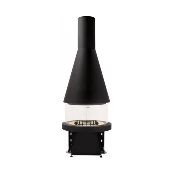
2.0 TECHNICAL DATA AND SPECIFICATIONS 2.1 DESCRIPTION OF THE APPLIANCE The highly original stove M360 is ideal for anyone seeking an unusual form of fireplace. The extensive glazed surface and a clean-cut, linear front to the firebox offer an unparalleled view of the fire. The combustion air is self-regulating and ensures that the glass remains clean all the way round. The simple controls for opening and closing the electrically operated glass panels ensure that this quality product is reliable and easy to use in all safety. -
Page 16: Accessories And Equipment
2.2 ACCESSORIES AND EQUIPMENT Description Accessories Grease spray Optional Ash drawer In kit Removable handle for smoke damper In kit Glove In kit Grate In kit Air intake grille 175x325 In kit Grille for enamelled plate In kit Smoke baffle plate In kit 2.3 FEATURES Fuel ........................ -
Page 17: Technical Data
2.5 TECHNICAL DATA Unit M360 Rated heat output 14.0 Consumption at rated heat output kg/h Thermal efficiency CO content (with 13% O2) Approved in accordance with standard EN 13229 Test report No. Flue diameter Hearth opening (diameter) Grate surface area 1810 Base weight Hood weight... -
Page 18: Dimensions
2.6 DIMENSIONS Non - Combustible Ceiling ( e.g. concrete ) M360 Firebox Installation Instructions February 2015... -
Page 19: Quick Guide
M360 Firebox Installation Instructions February 2015... -
Page 20: Wiring Diagram
2.7 WIRING DIAGRAM M360 Firebox Installation Instructions February 2015... - Page 21 PCB INTERNAL CONNECTIONS (CMF) (CMF) M360 Firebox Installation Instructions February 2015...
-
Page 22: Types Of Installation
3.0 TYPES OF INSTALLATION Description Packing size Weight (kg) Description (DxWxH) 128 x 61 x 59 Flat reinforced concrete and hollow tile mixed ceiling/floor H = 250/300 cm Flat reinforced concrete and hollow tile mixed ceiling/floor H = 300/580 cm 3 Sloping reinforced concrete and hollow tile 68.5 mixed ceiling/roof H = 300/580 cm... -
Page 23: Preparation For Installing
The product must be lifted using the indicated eyebolts. Do not hold the product by the glass frames that are still in a lowered position. Gruppo Piazzetta S.p.A. cannot be held responsible for any possible malfunction, damage to property or injury to persons due to incorrect unpacking, use or installation of the product. -
Page 24: Installation
5.0 INSTALLATION 5.1 CONNECTING THE BASE TO THE MAINS ELECTRICITY SUPPLY There must be a cable riser [A] under the base plus relative connection to a wall-mounted control panel in order for the product to be connected to the mains electricity supply (220V). By law the system must be properly earthed and fitted with a residual current circuit breaker. - Page 25 Prepare a round hole 0 30 cm in the reinforced concrete and hollow tile ceiling [B] (the ceiling must be no more than 30 cm thick). Insert the pipe with cover. (Fig. 26) With a ceiling other than in reinforced concrete and hollow tiles with height between 250/300 cm, as shown to the side (e.g.
- Page 26 The split ring collars are fixed to the ceiling through plugs inserted into the relative holes [F]. (Fig. 30) Make sure that the fastening and the plugs being used satisfy the requirements of resistance necessary for guaranteeing that the hood and relative connections are supported.
-
Page 27: Hood Installation
The product must be lifted using the indicated eyebolts. Do not hold the product by the glass frames that are still in a lowered position. Gruppo Piazzetta S.p.A. cannot be held responsible for any possible malfunction, damage to property or injury to persons due to incorrect use or installation of the product. - Page 28 Put the base template [D] at the bottom of the base [A] with the folds/ flanges directed downwards. (Fig. 37) Insert the plumb line [F] through the hole in the middle of the locating template [E] and adjust it until the weight just touches the base template [D]. (Fig. 38) The base [A] is centred by grasping its feet and making the tip of the plumb line coincide with the base template [G].
- Page 29 Connect the 220V [O] power cable and power the control unit [P]. Enter the maintenance mode (see "USE" and "MAINTENANCE"). (Fig. 41) Raise one of the two glass panels [Q] slowly until it is near the hood. Stop before it reaches the plate [R] by releasing the button. There are mechanical parts in movement during this procedure: use the product with care.
-
Page 30: Positioning The Edging Trim
5.5 POSITIONING THE EDGING TRIM Free the cable (A) with the control buttons (B) fastened to it, by cutting the band that secures it to the control unit (C) inside the base. The control buttons (B) must be installed where the two holes (F) have been made on the edging trim (D). -
Page 31: Use
6.0 USE Certain basic facts can be all-important for best performance and getting the most out of your appliance. Please find below some basic information intended to be of use with regard to the choice of firewood, the adjustment of the dampers and proper operation of the appliance. During operation, some parts of the appliance (door, handle, dampers, surround) can reach high temperatures. -
Page 32: Smoke Damper Regulation
6.2 SMOKE DAMPER REGULATION The damper has 7 set positions; the damper handle turns in steps. When lighting the fire, put the smoke damper to "OPEN" (position III) until a bed of embers has formed. This position may vary according to the atmospheric conditions, the type of flue and consequently the draught. -
Page 33: Lighting
When the appliance has cooled down, find the cause of the problem and if necessary In the event of overheating or if some appliance parts of the flue turn red: call in specialised personnel (C.A.T. - Piazzetta After-Sales Service Centre). immediately stop the supply of fuel;... -
Page 34: Maintenance
7.0 MAINTENANCE In compliance with current safety laws for electrical appliances, it is compulsory to contact a Gruppo Piazzetta After-Sales Service Centre or qualified personnel for all work involving installation, maintenance or servicing/repair which involves access to the inside of the cladding or the smoke chamber. -
Page 35: Cleaning The Ash Tray (Daily)
7.5 CLEANING THE ASH TRAY (DAILY) The grate and the ash tray must be cleaned daily. Using the grate for a whole day contributes to the accumulation of ash or residual combustion products. If cleaning is not done regularly there will be an excess of residues, which will affect appliance efficiency. The ash tray also needs emptying regularly, because if it fills up and obstructs the grate grid it will cause appliance malfunction. -
Page 36: Replacing The Glass
7.9 ACCESSING THE INSIDE OF THE PRODUCT Enter the "maintenance mode" (see "MAINTENANCE MODE"). Lower one of the glass panels (or both) and cut off the power to the product by putting the wall-mounted double pole switch to "OFF". Remove, in the following order: the grid [A], the ash box [B] and the Aluker elements [C]. - Page 37 Work to be carried out by at least two persons. Remove the screw [D] and the washer [E], working from the inside, and rotate the lever [F], which moves the glass panel clamp, so that it no longer presses against the frame. (Fig. 50) Remove the damaged glass, handling it with care.
-
Page 38: Replacing The Control Unit Assembly
7.11 REPLACING THE CONTROL UNIT ASSEMBLY The control unit assembly must be replaced if there is serious malfunctioning of the electronics or if it no longer works following a current overload due, for example, to lightning. If both glass panels have remained in the closed position, at least one must be opened with the emergency procedure in order to access the interior of the product. -
Page 39: Lubricating The Internal Guides
7.12 LUBRICATING THE INTERNAL GUIDES The glass panel frames are supported on the inside by straight guides that require periodic maintenance: the guides must be clean and adequately lubricated. Enter "maintenance mode" (see "MAINTENANCE MODE"). Lower the glass panel (or both) and then cut off the power supply to the product. -
Page 40: Removing The Smoke Baffle Plates
7.14 REMOVING THE SMOKE BAFFLE PLATES The fireplace is fitted inside above the grate with a baffle plate, which has the function of deflecting the route taken by the smoke thereby increasing the heat exchange surface area. The baffle plate rests on the supports that can be seen in the figure. The baffle plate rests on the supports that can be seen in the figure. -
Page 41: Troubleshooting
The manufacturer shall not be liable for any problems caused by lack of or inefficient maintenance or by failure to comply with the instructions in the product installation and operating guide. This instruction booklet contains all the useful information for installation, operation and maintenance. Only call the Gruppo Piazzetta S.p.A. service centre after having scrupulously followed all the instructions. - Page 42 M360 Firebox Installation Instructions February 2015...
- Page 43 M360 Firebox Installation Instructions February 2015...
- Page 44 M360 Firebox Installation Instructions February 2015...
- Page 45 M360 Firebox Installation Instructions February 2015...
- Page 46 M360 Firebox Installation Instructions February 2015...
- Page 47 M360 Firebox Installation Instructions February 2015...
- Page 48 ROBEYS LTD GOODS ROAD INDUSTRIAL ESTATE BELPER DERBYSHIRE DE56 1UU TEL: 01773 820940 FAX: 01773 820477 EMAIL: INFO@ROBEYS.CO.UK Product serial number, to be quoted when requesting service from the Gruppo Piazzetta After-Sales Service Centre. M360 Firebox Installation Instructions February 2015...
Need help?
Do you have a question about the M 360 and is the answer not in the manual?
Questions and answers