Danfoss FCD300 Service Manual
Hide thumbs
Also See for FCD300:
- Design manual (156 pages) ,
- Operating instructions manual (112 pages) ,
- Installation instructions (4 pages)

Related Manuals for Danfoss FCD300


Summary of Contents for Danfoss FCD300
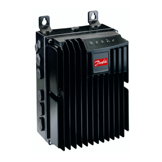
- Page 1 Service Manual FCD 300 Service Manual for FCD300 Release 01/2003 Revise 08/01/2003 by DD Service Manager, Steffen Sundbæk...
- Page 2 Service Manual FCD 300 General warning and your safety General warning The voltage of the frequency converter is dangerous whenever the converter is connected to mains. Incorrect fitting of the motor or frequency converter may cause damage to the equipment, serious injury or death. Consequently, it is essential to comply with the instructions in this manual as well as local and national rules and safety regulations.
-
Page 3: Table Of Contents
Service Manual FCD 300 Content Scope and field of service manual ....................4 Service Policy for FCD 300 ......................4 2.1. In General..........................4 2.2. Field Service ........................4 Installation, programming and basic fault tracing ...............4 Replacement..........................4 Spare parts............................5 5.1. Complete electronic parts.....................5 5.2. Control cards ........................5 5.3. -
Page 4: Scope And Field Of Service Manual
Scope and field of service manual This Service manual is made with the purpose to help when doing technical service on the FCD300 in the field. The service manual will be updated continuous to be able to improved the service and always be up-to-date. -
Page 5: Spare Parts
Service Manual FCD 300 Spare parts 5.1. Complete electronic parts These part can be downsized / downgraded 1 (one) size FCD303 P T4 C66 EB R1 D0 F12 T00 C0 = Ordering no.178B1484 FCD307 P T4 C66 EB R1 D0 F12 T00 C0 = Ordering no.178B1485 FCD315 P T4 C66 EB R1 D0 F12 T00 C0 = Ordering no.178B1486 FCD330 P T4 C66 EB R1 D0 F12 T00 C0 = Ordering no.178B2301 All unit are complete spare unit with ProfiBus 12MB and extended brake. -
Page 6: Picture Of Control Cards
Service Manual FCD 300 5.4. Picture of Control cards ProfiBus 12 MB control card = Ordering no. 175N2338 – PCBID: 175N1300 (Also used for non-Bus and ProfiBus 3MB AS(i) control card = Ordering no. 175N2324 – PCBID: 175N1635 (also used to converting the electronic spare part to AS(i)) DeviceNet control card = Ordering no. -
Page 7: Picture Of Various Parts
Service Manual FCD 300 5.5. Picture of Various parts Service kit (All parts used in the installation box) = Ordering no. 175N2121 Converting kit to new control plug system = Ordering no. 175N2409 Release 01/2003 Revise 08/01/2003 by DD Service Manager, Steffen Sundbæk... - Page 8 Service Manual FCD 300 Service tool = Ordering no. 175N2404 LCP2 = Ordering no. 175N0131 Release 01/2003 Revise 08/01/2003 by DD Service Manager, Steffen Sundbæk...
- Page 9 Service Manual FCD 300 LCP2 cable = Ordering no. 175N0162 LCP2 remote mounting kit = Ordering no. 175N0160 LCP2 plug kit = Ordering no. 175N2118 Release 01/2003 Revise 08/01/2003 by DD Service Manager, Steffen Sundbæk...
-
Page 10: Product Notes
For description of modifications of the control plug see product note no 7 For description of the modification on the earth spring see product note no 8 Products notes can be found on Danfoss Drives intranet. Tools needed • Torx screw driver TX20 for joining /splitting electronic part and installation part. -
Page 11: Place, Tightening Torque And Sequence For Screws
Service Manual FCD 300 Place, tightening torque and sequence for screws Screw Torque Place / Tightening sequence type Inverter part TX20 3,0 Nm M5x34 screws Service M3x16 1,3 Nm Switch screws Earth- TX20 3,0 Nm ground M4x12 connections screws Plug and TX10 1,5 Nm installations... - Page 12 Service Manual FCD 300 TX20 5,0 Nm mounting on M5x16 motor. screws Plast cover TX10 1,5 Nm inverter part Control card TX10 1,5 Nm inside the plastic cover Release 01/2003 Revise 08/01/2003 by DD Service Manager, Steffen Sundbæk...
-
Page 13: Function Diagram
Service Manual FCD 300 Function diagram Ext. Brake Resistor temp. Mech. Main Brake Power Control Basic Motor Control Supply Aux. Ext. Power Supply Control Card : functional w. ext. 24V power LCP2 : safety isolation (PELV) Std./Field Analog I/O Relay RS 485 Digital inputs Digital output... -
Page 14: Special Conditions, Which Might Cause Problems
Service Manual FCD 300 Special conditions, which might cause problems • The earth connection must be good especially in PROFIBUS installations. It is important to fit a heavy connection from the frame of the controller having the PROFIBUS master (PLC) and all bus nodes. •... -
Page 15: Symptom / Causes Chart
Service Manual FCD 300 Symptom / Causes chart Symptom/Cause chart is generally directed towards the more experienced technician. The intent of this chart is to provide a range of possible causes for a specific symptom. In doing so, this chart provide a direction, but with limited instructions. Symptom Possible Causes •... - Page 16 Service Manual FCD 300 • Open motor winding Unbalanced motor phase currents. • Faulty motor connection • Fault in inverter section (see Symptom No.6.) Slight variations in phase currents are normal. Variations greater than 5% require investigation Release 01/2003 Revise 08/01/2003 by DD Service Manager, Steffen Sundbæk...
-
Page 17: Application Or Fcd Fault
Service Manual FCD 300 Application or FCD fault Measurement Possible fault Action Supply voltage imbalance Missing a phase from the Disconnect the drive and supply or the supply could measure the supply have the imbalance or the imbalance again on the drives rectifier could be supply lines (terminal 91, 92 defect. -
Page 18: Test (Measurement) On The Fcd
Service Manual FCD 300 Test (measurement) on the FCD The terminals below reference to the pin on the electronic part that connect to the terminal number on the installations part, when connected. The DC bus is availably on Terminal 82 (+UDC) and through the left hole in the plastic (- UDC). -
Page 19: Static Test
Service Manual FCD 300 13.1. Static test Checking DC bus charge Check the DC bus for remaining charge by measuring the (Multimeter in voltage voltage on the DC terminals. position) Measure between –UDC (hole) and +UDC (82). The voltage must be less than 10 Volt. Wait about 4 min. - Page 20 Service Manual FCD 300 Connect the positive (+) meter lead to –UDC terminal (hole). Static Test, IGBT circuit (Multimeter in check Connect the negative (-) meter lead to W (98), V (97) and U diodes position) (96) terminals in turn. Each reading should show a diode drop.
-
Page 21: Dynamic Test
Service Manual FCD 300 13.2. Dynamic test WARNING: These measurement are done with main supply connected to the unit, and therefore don’t touch anything without the right protection. This test is possibly to do with the service tool (175N2404) connected between the installations box and the electronic part. - Page 22 Service Manual FCD 300 Release 01/2003 Revise 08/01/2003 by DD Service Manager, Steffen Sundbæk...
-
Page 23: Led Indications
Service Manual FCD 300 LED indications Name Colour OK status Alternatives Function Status Yellow Status is OK of the FCD Corresponding to parameter setting. For further information see design guide - parameter number 26 and DeviceNet manual for specific DeviceNet signalling. Green OK status for the field bus used (If bus... -
Page 24: Power Up Test / Control Card Test
Service Manual FCD 300 Power up test / Control card test The diagnosis of the Drive consists of two tests: Power up test Extended CC test The Power up test is carried out every time the Drive is powered up and consists of: Checksum validation of calibration data stored in EEPROM Checksum validation of hardware and motor dependent parameters in EEPROM The extended power card test can be activated via the parameter 620 and consist of:... -
Page 25: Replacement Of Control Card
Service Manual FCD 300 Replacement of control card Remember to use ESD protection when changing the Control card 1 Remove flat band cables from control card 2 Dismount control card cover (5 screws pos 1, TX 10, torque 1,5 Nm) 3 Mount board stacker (included) into female plug (36 pole) 4 Dismount old control card and replace with new (3 screws TX 10, torque 1,5 Nm) 5 Remount control card cover and flat band cables... -
Page 26: Control Connections
Service Manual FCD 300 Control Connections Note: 31A is internally connected to terminal 50 (+10V) Note: G is internally connected to terminal 55 (24 V and 10 V ground) Note: 35 and 36 are galvanic isolated from control ground (only functional, not PELV) Power Connections Terminal Function Comment... -
Page 27: Useful Data (Supplement To The Design Guide)
Service Manual FCD 300 Useful Data (supplement to the design guide) Main electrical data. Model Input Full load Input Output Full load Power Power voltage input Phase frequency voltage output current current [V AC] [A] * [Hz] [HP] [kW] 3x380-480 3Ø... -
Page 28: Thermal Conditions / Derating
Service Manual FCD 300 19.1. Thermal conditions / derating Motor mount, top 380V, 4,5 kHz. Motor mount, top 480V, 0,37 - 0,55kW 4,5 kHz. 1,5kW 0,37 - 0,75 kW 1,1kW 0,75kW 1,5kW 1,1kW 100% 100% Amb. temp. Deg. C. Amb. temp. Deg. C. Wall mount, 380V, 4,5kHz. -
Page 29: Ac Mains Voltage Compatibility
This means that it is allowed to sell the units without any demands regarding specific type of pre-fuse. (Regarding UL) Circuit Breaker CTI25MB from Danfoss or similar should be used to full fill UL. 19.3. Mechanical brake control and supply Gatedrive protection Output voltage: 45% of the line voltage (single rectified mains supply). -
Page 30: Digital Outputs
If the digital output is overloaded, it will be turned off after 13 ms and once a second the output will be activated again. 19.5. LCP cable length Max. distance between LCP2 and FCD300: 3 m. Voltage level overview Voltage level description (DC link voltage) -
Page 31: Help And Support Contact
Failure reporting and complaint/analyse report 23.1. Failure reporting All failures have to be reported to Danfoss Drives, via Fault Registration Form or the WIIS fault registration system (preferred). Drives or parts exchanged within warranty must be stocked for 2 months and returned if further investigations on request from DD. - Page 32 Service Manual FCD 300 Warning: It can be extremely dangerous to touch the electrical parts even when the AC line supply has been disconnected. For FCD 300: wait at least 4 minutes. Release 01/2003 Revise 08/01/2003 by DD Service Manager, Steffen Sundbæk...