Table of Contents
Advertisement
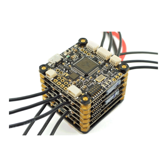
TBS POWERCUBE - Multirotor Stack
All-in-one racing flight control, speed control and power distribution
Revision 2017-03-09
The next generation plug&play RACE system. Design optimized for ultimate performance and reliability.
Compatible with any multi-rotor frame.
Key features
•
Ultra-lightweight and high-performance multi-rotor stack
•
Designed to be bundled and sold with any 120 to 330mm size frame
•
Stacked boards for extreme durability
•
Based on fast STM32F3 flight controller
•
Innovative patent-pending wire-free power distribution through stand-offs
•
True plug & play, no soldering required
•
Cost-efficient and field-repairable
•
Tested, developed and flown by the world's leading pilots
•
Highest quality aluminum screws, brass standoffs and electronic components
•
Standard 36x36mm dimension, 70g incl. PDB, wires & connectors
•
Upgradable from compact to extreme configurations
1
p atented!
Advertisement
Table of Contents
Troubleshooting

Related Manuals for tbs electronics PowerCube


Summary of Contents for tbs electronics PowerCube
-
Page 1: Key Features
TBS POWERCUBE - Multirotor Stack p atented! All-in-one racing flight control, speed control and power distribution Revision 2017-03-09 The next generation plug&play RACE system. Design optimized for ultimate performance and reliability. Compatible with any multi-rotor frame. Key features •... -
Page 2: Specifications
5V for receiver and FC over internal BUS System Cleanflight or B etaflight Software: with BST and pass-through ESC support, firmware: http://ww.team-blacksheep.com/powercube/colibri-latest.zip Compatibility: Tri-, quad- and hexacopters In/outputs: • 1x Receiver port - PPM, SBUS or SPEKTRUM (PPM, UART2, 5V, 3.3V) •... - Page 3 5V @ 4A N EW! , 12V @ 0.2A, combined max. draw Power supply: Connectors: Molex Picoblade 1.25mm, 4-pin for VTX and CAM, 5-pin for BST TBS POWERCUBE - Stack details Working temperature: 0 C to 85 ...
- Page 4 Attention The TBS POWERCUBE, when installed, can easily damage property or extremities if not used properly. Always ensure that no propellers are installed when configuring, installing or tuning your multirotor. We also recommend to use the options “Spin motor when armed” and use stick commands to arm your multirotor, rather than switches.
-
Page 5: Table Of Contents
Mounting on your frame Carbon fiber frames Finalizing your installation The first flight TBS POWERCUBE on the TBS VENDETTA quadcopter TBS FPVision - CORE PRO OSD, UNIFY PRO VTX, VID SWITCH, BEEPER, DCDC RC Calibration - Push button Camera port switch... - Page 6 TBS Elite Bundle / External ESC PDB layer TBS POWERCUBE Drag Race Shield Connecting TBS equipment Connectivity with TBS CORE PRO OSD TBS CORE PRO Connection Entering OSD configuration menu RC Calibration (mandatory) Calibrate new setup Read RC data from existing setup...
-
Page 7: Tbs Powercube Overview
TBS POWERCUBE Overview Check out the POWERCUBE in all its glory. The following diagrams indicate the locations of each component and their purpose. -
Page 8: Installation
TBS POWERCUBE. The tape isolates them from the carbon fiber frame. The ground-carrying standoffs should be used to bolt the TBS POWERCUBE onto the frame. In combination with the tape, this creates a very solid mount. -
Page 9: Carbon Fiber Frames
Make sure that no power carrying elements can get in touch with the carbon frame except ground (Powercube GND, VTX antenna socket etc.). Pay special attention to motor phases, also make sure the screws are not too long to push up into the motor... -
Page 10: Finalizing Your Installation
TBS PowerCube stack. The arrow on the board must face flight forward. Also, verify that the motor spin directions are correct. -
Page 11: Tbs Powercube On The Tbs Vendetta Quadcopter
TBS POWERCUBE on the TBS VENDETTA quadcopter The TBS VENDETTA has a full POWERCUBE installed at its core. It powers the R/C receiver, flight control, motors, buzzer, LED backplate and DCDC power system. The OSD is powered by a separate TBS CORE PRO. -
Page 12: Rc Calibration - Push Button
CORE PRO stack. The TBS FPVision directly replaces the bottom layer (PDB V1 or V2) in the normal POWERCUBE stack, the Unify Pro VTx and the CORE PRO OSD in your build. The stacking height or other functionality is not affected. -
Page 13: Camera 5V/12V Software Selector
If the OSD times out, or you select EXIT, move your ROLL stick to left for 3 seconds to re-enter the CORE PRO OSD. Camera 5V/12V software selector The camera port is set to 5V from the factory. To change the output voltage to 12V, connect the TBS FPVision to the ... -
Page 14: Tbs Colibri V2 - Flight Control
The TBS COLIBRI RACE edition is a barebone version of the TBS COLIBRI (debuted in the TBS GEMINI), built specifically for the TBS POWERCUBE. Flashed by default with Cleanflight to allow maximum tuning capabilities for racers, with multiple innovative features such as built-in IR port, MPU6500 with serial support (insanely low looptimes!!), USB VCP, JST-SH plug&play ports, as well as solder sockets for the most critical input and... -
Page 15: Overview And Connections
ESC Outputs (V2) - Control signal output connector for 4 ESCs Pin-out from left: ESC4&GND / ESC3&GND / ESC2&GND / ESC1&GND These are not used when part of the TBS POWERCUBE, then there are pads on the PDB V2 •... -
Page 16: East
East • Micro-USB - Connect via USB for configuration via CleanFlight/BetaFlight and firmware upgrades • SWD header (V1) - Used for direct microcontroller programming Boot button (V2) - To enter DFU mode for firmware upgrade •... -
Page 17: South
South V1&V2: • LED_Strip - For directly connecting WS2812B, WS2812, and WS2811 based RGB LED strips Regulated 5V PWR provided to connector over internal BUS, no additional voltage regulator required! Any WS2812B LED boards with up to 32 LEDs should work Pin-out from left: Data Out / 5V / GND Signal-pin connects to DIN on WS28xx pads GPS/Mag/Alt (UART3) ... -
Page 18: West
West V1&V2: Stacking header pin-out: Stacking header - Connecting the different layers in the stack • Top row: PWM2, PWM4, PWM6, BST SCL, UART2_RX, +5V Bottom row: PWM1, PWM3, PWM5, BST SDA, UART2_TX, +5V PDB V2 and FPVision (NEW!) / +12V PDB V1 •... -
Page 19: Configuration And Tuning
Configuration and tuning The COLIBRI RACE runs Cleanflight by default. Cleanflight comes with a great and easy to use Chrome Application that you can download here: • CleanFlight Configurator There are several very detailed CleanFlight guides available, which teaches you how to tune, configure and calibrate your model (see FliteTest and Oscar Liang’s guides below). -
Page 20: Driver Installation
Driver installation The COLIBRI RACE is one of the first flight controllers that natively supports USB. In newer operating systems (Windows 10, Mac OS X 10.10) there are no drivers required to enable configuration. However, for the most users a new driver has to be installed manually. Download and install the following driver. •... - Page 21 4. Select a firmware from the drop-down menu (select “Vendetta” especially made for the TBS VENDETTA, these include pre-tuned settings) a nd click “UPDATE” - the process should finish within 15 seconds. To access beta-versions, press F1 and check off “Include beta releases”. 5.
-
Page 22: Updating Firmware Using Cleanflight
The TBS COLIBRI runs with a slightly customized CleanFlight, which you can grab here: • http://www.team-blacksheep.com/powercube/colibri-latest.zip If you do not need features such as BST or MultiFlash, or until these features are merged into the CleanFlight project, you can use the standard CleanFlight builds directly from the CleanFlight Configurator. -
Page 23: Cleanflight Configurator Issues
CleanFlight Configurator issues CleanFlight configurator runs as a Chrome app and therefore is at the mercy of Chrome’s driver support. In some instances, the STM drivers will not work. Even though the flight controller starts in DFU mode, CleanFlight configurator may not recognize your board. In this case, the instructions outlined here need to be followed: https://github.com/cleanflight/cleanflight-configurator/pull/250#issuecomment-146756746 Upgrade via DFU (developer use) -
Page 24: Tbs Bulletproof 25A Esc - Speed Control
ESC, for greater reliability. The ESCs stack into the TBS POWERCUBE in alternating fashion. The location in the stack determines which motor they are assigned to - assignment starts closes to the flight controller (from #1) and downward. -
Page 25: Firmware Upgrades
6. All your ESC should be listed 7. Flash them, using Flash BlHeli button 8. Make sure you restore the settings after flashing them, continue always hit enter will continue that The latest TBS POWERCUBE firmware for TBS BULLETPROOF and TBS COLIBRI RACE: • http://www.team-blacksheep.com/powercube/colibri-latest.zip... -
Page 26: Tbs Powercube Pdb V2 - Power Distribution
TBS POWERCUBE PDB V2 - Power distribution This board measures current and controls power distribution across the entire TBS POWERCUBE, provides regulated and filtered power for the ESCs, flight controller and FPV system. -
Page 27: Selecting Vtx And Cam Voltage
Selecting VTX and CAM voltage The output voltage for the VTX and CAM ports can be selectable on the PCB. By default is the CAM port set to 12V and the VTX set to 5V. If your equipment requires a different voltage (normally printed on the device or in the specifications), you have to switch the solder jumper bridge to the right voltage (5V or 12V.) You can even change the voltage for the VTX to VBatt if your video transmitter has an on-board regulator or requires more power than the TBS DCDC board can provide. -
Page 28: Connecting Fpv Camera And Transmitter
Connecting FPV camera and transmitter There are two ports on the PDB board which are for the FPV camera and video transmitter. Any TBS camera and transmitter is directly supported and plugs into the connector (Molex Picoblade) - be sure the output voltage is right for the equipment you are going to connect. - Page 29 It will require one small modification. All that needs to be done is to cut off one pin on the TBS POWERCUBE PDB (non-v2.0) stacking header. The pin is the extra pin 11, 12V DC supply. This pin is an additional 5V pin on newer TBS PDB V2 boards.
-
Page 30: Troubleshooting Fpv Transmitter / Camera
Troubleshooting FPV Transmitter / Camera • Only static on receiver, or no video (PDB V1 only) Verify that you have a working 5V and 12V supply by using a multimeter and measuring on the dedicated 5V/12V/GND pads near the BST connector. In case the 5V and 12V supply line is interrupted, you can try to fix it by soldering the 6 pin headers that connect the power distribution board with the TBS DCDC, especially on the TBS DCDCD side. - Page 31 If you prefer, or need to use, your own external ESCs for a customized setup, you can do this by using the special external ESC board for the POWERCUBE. It allows you to solder 4 ESCs to the board, including the control signal.
- Page 32 TBS POWERCUBE Drag Race Shield With motors and propellers becoming more and more power hungry, the Drag Race capacitor shield adds 2200uF of capacitance to your power supply. This works essentially as a short term energy storage, with huge discharge capabilities.
- Page 33 Connecting TBS equipment There is an issue when you want to run BST devices like the GPS or BLACKBOX direct without a CORE PRO. Most of the BST devices needs 5V which the CORE PRO provides. The CROSSFIRE RX does not power the BST line when 5V is applied to the servo connectors.
- Page 34 TBS CORE PRO Connection The POWERCUBE has a BST connector on the PDB layer which allows a connection to the CORE PRO. This connection provides battery power and current sensor data for the OSD on the CORE PRO. The FPV transmitter and camera must be connected to the CORE PRO not the POWERCUBE for the OSD to work.
- Page 35 Entering OSD configuration menu After the initial calibration is done, the main OSD overlay will show and the CORE PRO is ready to be configured. 1. To enter the OSD configuration menu, hold the throttle stick down-left for 4 seconds (mode 2) 2.
- Page 36 Centering your sticks will start the countdown. If Follow the instructions on the screen and move your you are not using the currently-active RX provider sticks accordingly. If the direction does not match, it (in this case SBUS), push the center (Enter) button of needs to be adjusted in your R/C radio the CORE PRO to cycle through the available configuration.
- Page 37 Read RC data from existing setup If you already have everything set up on your POWERCUBE and you are just adding the CORE PRO, select “READ CLEANFLIGHT RC DATA” in the CORE PRO menu and the CORE PRO will apply the settings from your CleanFlight setup.
- Page 38 The ESCs know their spot in the TBS POWERCUBE, so starting from the top down they are tied to motor #1 to #6 according to their position in the stack from the flight control layer.
-
Page 39: Troubleshooting
Tuning The stock standoffs are made from brass to keep money in your pockets or rainy day funds. For the serious weight aficionado, aluminum-gold based standoffs are available. They will shed around 12g off the total AUW, while improving conductivity and thus the maximum power throughput. Further optimization can be done by using conformal coating on the PCB surface, to protect your ESCs against the elements. - Page 40 Good practices We have compiled a list of all of practices which have been tried and tested in countless environments and situations by the TBS crew and other experienced FPV pilots. Follow these simple rules, even if rumors on the internet suggest otherwise, and you will have success in FPV. ●...
- Page 41 ● Do not use diversity video receivers as a replacement for pointing your antennas, diversity should be used to mitigate polarization issues. Improving the antenna gain on the receiver end is better than increasing the output power (except in ● RF-noisy areas).
Need help?
Do you have a question about the PowerCube and is the answer not in the manual?
Questions and answers