Table of Contents
Advertisement
Quick Links
Advertisement
Table of Contents

Related Manuals for Buchi Encapsulator B-390


Summary of Contents for Buchi Encapsulator B-390
- Page 1 Encapsulator B-390 Operation Manual 11593477E en...
- Page 2 E-Mail: quality@buchi.com BUCHI reserves the right to make changes to the manual as deemed necessary in the light of experience; espe- cially in respect to structure, illustrations and technical detail. This manual is copyright. Information from it may not be reproduced, distributed, or used for competitive purpos- es, nor made available to third parties.
-
Page 3: Table Of Contents
Installation site........19 Installing the Encapsulator B-390 ......20 Electrical connections . - Page 4 Table of contents Operation . . . . . . . . . . . . . . . . . . . . . . . . . . . . . . . . . . . . . . . . . . 31 Starting up the instrument .
-
Page 5: About This Manual
1 About this manual About this manual This manual describes the Encapsulator B-390. It provides all information required for its safe opera- tion and to maintain it in good working order. It is addressed to laboratory personnel in particular. If the instrument is used in a manner not specified in this manual, the protection provided by the instrument may be impaired. -
Page 6: Safety
The bead formation is based on the fact that a controlled, laminar liquid jet is broken into equally sized beads, if vibrated at an optimal frequency. The Encapsulator B-390 provides just such controlled conditions to generate beads between 0.15 to 2 mm. The instrument is ideally suited to encapsulate particles < 50 µm. -
Page 7: Safety Warnings And Safety Signals Used In This Manual
2 Safety 2 .4 Safety warnings and safety signals used in this manual DANGER, WARNING, CAUTION and NOTICE are standardized signal words for identifying risk levels, related to personal injury and property damage. All signal words, which are related to personal injury are accompanied by the general safety sign. - Page 8 2 Safety Explosive gases, explosive environment Harmful to live-forms Device damage Pressurized gas/air Hot Surface Wear laboratory coat Wear protective goggles Wear protective gloves Additional user information Paragraphs starting with NOTE transport helpful information for working with the device/software or its supplementaries.
-
Page 9: Product Safety
2 Safety 2 .5 Product safety Safety warnings in this manual (as described in section 2.4) serve to make the user alert and to avoid hazardous situations emanating from residual dangers by giving appropriate counter measures. However, risks to users, property and the environment can arise when the instrument is damaged, used carelessly or improperly. -
Page 10: Safety Measures
2 Safety Notice Risk of instrument damage by wrong mains supply. • External mains supply must meet the voltage given on the type plate. • Check for sufficient grounding. Notice Risk of damaging labratory glasses or utensils by moving syringe pump unit. •... -
Page 11: General Safety Rules
Modifications to the instrument are only permitted after prior consultation with and with the written approval of the manufacturer. Modifications and upgrades shall only be carried out by an authorized BUCHI technical engineer. The manufacturer will decline any claim resulting from unauthorized modifi- cations. -
Page 12: Technical Data
The scope of delivery can only be checked according to the individual delivery note and the listed order numbers. NOTE For additional information about the listed products, see www.buchi.com or contact your local dealer. 3 .1 .1 Standard instrument Table 3-1: Standard instrument Product Order no. -
Page 13: Standard Accessories
3 Technical data 3 .1 .2 Standard accessories Table 3-2: Standard accessories Set of 8 single nozzles 11057918 Set of 8 single nozzles with high precision opening of 0.08, 0.12, 0.15, 0.20, 0.30, 0.45, 0.75 and 1.00 mm, made of stain- less steel 316L including nozzle rack Pressure bottle 500 mL 11058190... -
Page 14: Recommended Spare Parts
3 Technical data 3 .1 .4 Recommended spare parts Table 3-4: Recommended spare parts Product Order no. O-ring set for single nozzle 11057954 O-ring set for concentric nozzle 11057955 Pre-filters for nozzle, 11057957 diameter 7 mm (10 pcs.) Drain filters for reaction vessel, 11057958 diameter 35 mm (10 pcs.) B-390 Operation Manual, Version E... -
Page 15: Technical Data
3 Technical data 3 .2 Technical data Table 3-5: Technical data Encapsulator B-390 Power consumption max. 150 W Connection voltage 100–240 VAC Mains supply voltage fluctuations up to ±10% of the nominal voltage Frequency 50/60 Hz Fuse 3.15 A Dimensions (W × H × D) 32×29×34 cm... -
Page 16: Description Of Function
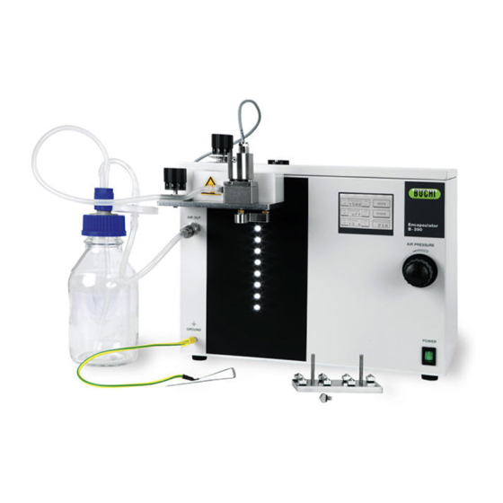
4 Description of function Description of function This chapter explains the basic working principle of the Encapsulator B-390. It also shows how the instrument is structured and provides a general functional description of its assembly. 4 .1 Functional principle The instrument provides the following key functions: Reproducible bead size from one production to the next –... - Page 17 4 Description of function Figure 4-1: Schematic representation of the Encapsulator B-390 a Pressure bottle Vibration control Bead producing unit LED/stroboscope Vibration unit Polymerization bath Single nozzle Magnetic stirrer Electrode (P) Air pressure ...
-
Page 18: Connections At The Encapsulator B-390
4 Description of function The main parts of the Encapsulator B-390 are the control unit, the bead producing unit, and the pres- sure bottle. All parts of the instrument which are in direct contact with the immobilization mixture can be sterilized by autoclaving. -
Page 19: Putting Into Operation
5 Putting into operation Putting into operation This chapter describes how the instrument has to be installed. It also gives instructions for the initial startup. NOTE Inspect the instrument for damages during unpacking. If necessary, prepare a status report imme- diately to inform the postal company, railway company or transportation company. -
Page 20: Installing The Encapsulator B-390
5 Putting into operation 5 .2 Installing the Encapsulator B-390 Place the instrument on the lab bench with convenient access to an AC electrical outlet and to compressed air. Place the instrument in a way that disconnection of the electric supply plug is possible at all times. -
Page 21: Electrical Connections
5 Putting into operation Installation of the air line A 3 m air tube (2.6×4.0 mm) is included with each Encapsulator to connect it to external compressed air or nitrogen. 1. Stick the air tube into the air inlet plug. 2. -
Page 22: Assembling Of The Bead Producing Unit
5 .4 Assembling of the bead producing unit The bead producing unit is the central part of the Encapsulator B-390. It is fully autoclavable. Figure 5-3 shows the different parts of the bead producing unit. The assembled bead producing unit is attached with the screw ... -
Page 23: Electrode
5 Putting into operation 5 .6 Electrode The electrode is part of the electrostatic dispersion unit. It is attached from below to the heating block. The distance between the electrode and the nozzle tip can be changed as needed. This distance is approximately 3 to 8 mm. - Page 24 5 Putting into operation Figure 5-7: Position of the electrode below the carrier plate Figure 5-8: Grounding the polymerization bath B-390 Operation Manual, Version E...
-
Page 25: Pressure Bottle
5 Putting into operation 5 .7 Pressure bottle The pressure bottle is an autoclavable container used to push the encapsulation mixture by air pres- sure into the bead producing unit. Figure 5-9 shows the different parts of the pressure bottle. The glass recipient has a guaranteed pressure resistance of 1.5 bar. -
Page 26: Installation Of The Pressure Bottle
5 Putting into operation 5 .7 .1 Installation of the pressure bottle 1. Assemble and – if needed - autoclave the pressure bottle. 2. Fill the bottle with the immobilization mixture. 3. Attach the silicone tube of the pressure bottle to the luer lock inlet of the bead producing unit. -
Page 27: Option: Concentric Nozzle System
5 Putting into operation 5 .8 Option: Concentric nozzle system The concentric nozzle system (CN system) is an optional kit to the single nozzle unit. It is for the production of capsules in a one-step procedure. The system consists of CN bead producing unit, a set of 7 shell nozzles (0.20, 0.30, 0.40, 0.50, 0.60, 0.70 and 0.90 mm) and one pressure bottle of 1000 mL. - Page 28 5 Putting into operation Figure 5-13: CN bead producing unit with set of 7 shell nozzles. The following nozzle apertures are standard: 0.20, 0.30, 0.4, 0.50, 0.60, 0.70 and 0.90 mm. Figure 5-14: Single parts of the CN bead producing unit a Screw M3×6 ...
-
Page 29: Mounting Of Cn Nozzles
5 Putting into operation 5 .8 .1 Mounting of CN nozzles Put the O-ring 12.42×1.78 in the grove of the CN bead producing unit. Put the inner nozzle (with attached O-ring) into the hole of the CN bead producing unit. There is no thread. The inner nozzle is centered and fixed by the shell nozzle. -
Page 30: Final Installation Check
5 Putting into operation Attach the complete CN bead producing unit to the carrier plate with two screws (M3×25). Attach the silicone tube of the core liquid to the core inlet port and the silicone tube of the shell liquid to the shell inlet port. -
Page 31: Operation
See also section 2.5 “Product safety” for general warnings. 6 .1 Starting up the instrument • Make sure the Encapsulator B-390 is properly connected to the mains supply. • Carry out a final installation check (see section 5.9) before every bead production. •... - Page 32 6 Operation The frequency regulation generates the appropriate elec- tric oscillation in the vibration unit. Pressing on the (+) and (–) buttons will change the frequency. Pressing the “on/off” button activates or deactivates frequency. Pressing “Esc” will return you to the start menu and the set value will be kept.
-
Page 33: Menu Structure Of The Control Unit
Screen 6-5: More options concerning amplitude of vibration and light Intensity of the stroboscope lamp. 6 .3 Menu structure of the control unit The figure below shows a schematic overview of all menus of the Encapsulator B-390, each with the available functionality. Main menu Frequency On/Off... -
Page 34: Manual Air Pressure Control
6 Operation 6 .4 Manual air pressure control In the control unit the pressure is manually controlled by the pressure regulating valve, integrated in the front panel of the control unit (see figure 6-2). Set the air pressure at a value which is 0.2 to 0.3 bar higher than the maximal air pressure needed during the encapsulation procedure;... -
Page 35: Practicing With The Encapsulator, Using Water
6 Operation 6 .5 Practicing with the Encapsulator, using water Before working with encapsulation polymers, use water for practicing with the Encapsulator to become familiar with the effects of the controls. 1. Assemble the bead producing unit, screw the 0.30 mm single nozzle to the bead producing unit and attach all on the carrier plate with the screw (M3×25). - Page 36 6 Operation Table 6-1: Determination of the working field (with pressure bottle) Nozzle size: Air pressure Clear bead chain without Clear bead chain with electrostatic tension electrostatic tension Lowest Highest Electrostatic Lowest Highest frequency frequency Voltage frequency frequency Nozzle size: Clear bead chain without Clear bead chain with Air pressure...
- Page 37 6 Operation 7. Set the liquid flow rate and the vibration frequency to a value where a clear bead chain is obtained. Activate the electrostatic dispersion unit at 300 V and increase the tension stepwise by 100 V until the one-dimensional liquid jet is transformed into a funnel-like multi-line stream. The higher the electrostatic charge the earlier the bead chain is separated.
-
Page 38: Practicing With The Encapsulator, Using Alginate Solution
6 Operation 6 .6 Practicing with the Encapsulator, using alginate solution After getting comfortable with the bead formation controls, perform test runs with non-sterile algi- nate solutions. Sodium alginate is the most commonly used polymer, but there are others in use with varying properties. -
Page 39: Working With Alginate Solution
6 Operation 6 .6 .2 Working with alginate solution 1. Attach a 200 µm or 300 µm nozzle to the assembled bead producing unit. Attach all to the carrier plate. Check that the electrode is attached. Put the vibration unit on the bead producing unit. Put a magnetic stirrer below the nozzle and a large beaker on the stirrer. - Page 40 6 Operation NOTE The stronger the circular dispersal of the bead stream the better is the bead homogeneity. This does not only depend on the electrostatic tension, but the liquid flow rate and the vibration frequency are also factors. Ideally, the bead should separate from the liquid jet within the electrostatic field between the nozzle and the end of the electrode.
-
Page 41: Theoretical Background
6 Operation 6 .7 Theoretical background Equ. 1: When a laminar jet is mechanically disturbed at the frequency ƒ, beads of uniform size are formed . The optimal wavelength λ breakup, according to Weber is given by: Equ. 2: where: D = nozzle diameter η... - Page 42 6 Operation Figure 6-4: Influence of the liquid jet velocity and the nozzle diameter on flow rate, as calculated by Equation 4. Figure 6-5 shows the correlation between the vibration frequency and the bead diameter for five different flow rates as calculated by equation 4. Lower flow rates, which corresponds to lower pumping rates, produce smaller beads.
-
Page 43: Bead Productivity And Cell Density
6 Operation Table 6-4: Optimal working conditions for the Encapsulator determined with alginate solution Nozzle diameter [µm] Flow rate * [mL/min] Frequency interval ** Amplitude Air pressure [bar] 1.0 mm 30 to 40 40 to 220 Hz 2 to 6 0.3 to 0.6 750 µm 19 to 25... - Page 44 6 Operation Figure 6-6: Amount of beads with a diameter of 0.3 to 0.6 mm formed from 1 mL of immobilization mixture. Figure 6-7: Amount of beads with a diameter of 0.6 to 1.1 mm formed from 1 mL of immobilization mixture. B-390 Operation Manual, Version E...
- Page 45 6 Operation Figure 6-8: Amount of cells per bead made from different cell concentrations for bead diameters of 0.3 to 0.6 mm. Figure 6-9: Amount of cells per bead made from different cell concentrations for bead diameters of 0.6 to 1.1 mm. B-390 Operation Manual, Version E...
-
Page 46: Maintenance And Repairs
Such training and knowledge can only be provided by BUCHI. Addresses of official BUCHI customer service offices are given on the BUCHI website under: www.buchi.com. -
Page 47: Cleaning
7 Maintenance and repairs 7 .4 Cleaning Warning Pressure increase in the inlet-system due to clogged nozzles. Bursting of the inlet system. Death or serious poisoning by contact or incorporation of harmful substances at use. • Clean nozzle immediately after use, see following section. Wear laboratory coat Wear protective goggles Wear protective gloves... -
Page 48: Cleaning A Clogged Nozzle
7 Maintenance and repairs Figure 7-1: Cleaning procedure of the nozzle – Take a syringe containing air on top and water on the bottom. – Push the air through the nozzle (left figure). – Push the water through the nozzle immediately afterwards (right figure). –... -
Page 49: Troubleshooting
8 Troubleshooting Troubleshooting 8 .1 Malfunctions and their remedy The table below lists possible operating errors and their cause. As remedy set the parameter stepwise in the opposite direction or fix the missing part. Table 8-1: Possible cause Problem Possible cause Unstable liquid stream The liquid flow rate is too low. -
Page 50: Shutdown, Storage, Transport And Disposal
Switch off the instrument and remove the power cord. Wait until all hot parts (e.g. heating block and carrier plate) have cooled down. To disassemble the Encapsulator B-390 follow the installation instructions in section 5 in reverse order. Remove all liquids and dusty residues before packaging the instrument. -
Page 51: Disposal
9 Shutdown, storage, transport and disposal 9 .2 Disposal For instrument disposal in an environmentally friendly manner, a list of materials is given in chapter 3.3. This helps to ensure that the components can be separated and recycled correctly. You have to follow valid regional and local laws concerning disposal. For help, please contact your local authorities! NOTE When returning the instrument to the manufacturer for repair work, please copy and complete the... -
Page 52: Declarations And Requirements
10 Declarations and requirements Declarations and requirements 10 .1 FCC requirements (for USA and Canada) English: This equipment has been tested and found to comply with the limits for a Class A digital device, pursuant to both Part 15 of the FCC Rules and the radio interference regulations of the Canadian Department of Communications. -
Page 53: Health And Safety Clearance Form
10 Declarations and requirements 10 .2 Health and Safety Clearance form Health and Safety Clearance Declaration concerning safety, potential hazards and safe disposal of waste. For the safety and health of our staff, laws and regulations regarding the handling of dangerous goods, occupational health and safety regulations, safety at work laws and regulations regarding safe disposal of waste, e.g. - Page 56 T +55 19 3849 1201 F +66 2 862 08 54 F +971 4 313 2861 F +55 19 3849 2907 bacc@buchi.com middleeast@buchi.com latinoamerica@buchi.com www.buchi.com www.buchi.com www.buchi.com We are represented by more than 100 distribution partners worldwide. Find your local representative at: www.buchi.com...
Need help?
Do you have a question about the Encapsulator B-390 and is the answer not in the manual?
Questions and answers