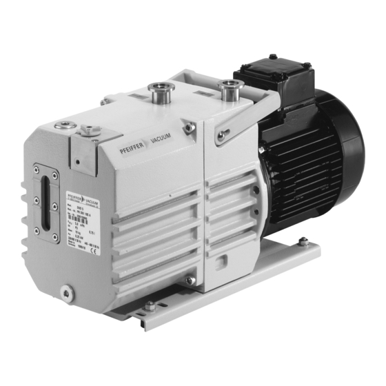
Pfeiffer Vacuum DUO 5 M Operating Instructions Manual
Rotary vane pump
Hide thumbs
Also See for DUO 5 M:
- Operating instructions manual (64 pages) ,
- Operating instructions manual (40 pages) ,
- Operating instructions manual (38 pages)

Related Manuals for Pfeiffer Vacuum DUO 5 M


Summary of Contents for Pfeiffer Vacuum DUO 5 M
-
Page 1: Fig. 21: Content Of Maintenance Kit 1 - Maintenance Level
OPERATING INSTRUCTIONS Translation of the Original DUO 5 M | DUO 5 MC Rotary vane pump... - Page 2 Dear Customer, Thank you for choosing a Pfeiffer Vacuum product. Your new rotary vane pump is designed to support you by its performance, its perfect operation and without interfering your individual application. The name Pfeiffer Vacuum stands for high-quality vacuum technology, a comprehensive and complete range of top-quality products and first-class service.
-
Page 3: Table Of Contents
Limits of use of the product Proper use Foreseeable improper use Personnel qualification 2.8.1 Ensuring personnel qualification 2.8.2 Personnel qualification for maintenance and repair 2.8.3 Advanced training with Pfeiffer Vacuum Product description Function Operating principle Product features Identifying the product... - Page 4 Recommissioning Recycling and disposal General disposal information Dispose of rotary vane pump Malfunctions Service solutions by Pfeiffer Vacuum Spare parts 12.1 Spare part packages 12.2 Maintenance kit 1 – maintenance level 1 12.3 Overhaul kit – Maintenance level 3 12.4 Coupling set for versions with magnetic coupling 12.5 Set of vanes...
- Page 5 Troubleshooting for rotary vane pumps Tbl. 9: Spare part packages Tbl. 10: Content of maintenance kit 1 Tbl. 11: Accessories for Duo 5 M Tbl. 12: Accessories for Duo 5 MC Tbl. 13: Consumables Tbl. 14: Conversion table: Pressure units Tbl.
- Page 6 Dimension diagram Duo 5 M | single-phase motor (115 V) Fig. 23: Dimension diagram Duo 5 M | single-phase motor (230 V) Fig. 24: Dimension diagram Duo 5 M | single-phase motor (230 V, hose connection) Fig. 25: Dimension diagram Duo 5 M | three-phase motor 6/60...
-
Page 7: About This Manual
Keep the manual for future consultation. 1.1 Validity This operating instructions is a customer document of Pfeiffer Vacuum. The operating instructions de- scribe the functions of the named product and provide the most important information for the safe use of the device. The description is written in accordance with the valid directives. The information in this op- erating instructions refers to the product's current development status. -
Page 8: Stickers On The Product
About this manual Note 1.3.3 Stickers on the product This section describes all the stickers on the product along with their meanings. Rating plate (example) VACUUM D-35641 Asslar The rating plate is located on the front right side next to the sight glass Mod.: DUO 5 Mod.-Nr.: PK D61 XXX... -
Page 9: Abbreviations
About this manual 1 – 4 Fig. 1: Position of the stickers on the product 1 Fill oil note Sense of rotation sticker 2 Check direction of rotation note Optionally: Note F4 Operating fluid 3 Note F4 Operating fluid Optionally: Note D1 Operating fluid 4 Note D1 Operating fluid Rating plate 5 Warning hot surface... -
Page 10: Safety
Safety 2 Safety 2.1 General safety information The following 4 risk levels and 1 information level are taken into account in this document. DANGER Immediately pending danger Indicates an immediately pending danger that will result in death or serious injury if not observed. ►... - Page 11 ► Install suitable touch protection if the vacuum pump is accessible to untrained persons. ► Allow the vacuum pump to cool down before carrying out any work. ► Contact Pfeiffer Vacuum for suitable touch protection in system solutions. Risks during operation...
- Page 12 ► Install suitable touch protection if the vacuum pump is accessible to untrained persons. ► Allow the vacuum pump to cool down before carrying out any work. ► Contact Pfeiffer Vacuum for suitable touch protection in system solutions. Risks during maintenance, decommissioning and malfunctions...
- Page 13 Safety WARNING Danger to life from electric shock in the event of a fault In the event of a fault, devices connected to the mains may be live. There is a danger to life from electric shock when making contact with live components. ►...
-
Page 14: Safety Precautions
Safety 2.3 Safety precautions Duty to provide information on potential dangers The product holder or user is obliged to make all operating personnel aware of dangers posed by this product. Every person who is involved in the installation, operation or maintenance of the product must read, understand and adhere to the safety-related parts of this document. -
Page 15: Proper Use
(F4, F5, A113) as operating fluid. ► Adhere to the installation, commissioning, operating, and maintenance instructions. ► Do not use any accessory parts other than those recommended by Pfeiffer Vacuum. 2.7 Foreseeable improper use Improper use of the product invalidates all warranty and liability claims. Any use that is counter to the purpose of the product, whether intentional or unintentional, is regarded as improper use;... -
Page 16: Ensuring Personnel Qualification
─ Customer with Pfeiffer Vacuum service training ─ Pfeiffer Vacuum service technician 2.8.3 Advanced training with Pfeiffer Vacuum For optimal and trouble-free use of this product, Pfeiffer Vacuum offers a comprehensive range of courses and technical trainings. For more information, please contact Pfeiffer Vacuum technical training. -
Page 17: Product Description
Product description 3 Product description 3.1 Function DuoLine rotary vane vacuum pumps are two-stage, oil-sealed rotary positive displacement pumps for use in coarse and medium vacuum. The vacuum pumps are equipped with a safety valve that vacuum seals the vacuum chamber and simultaneously vents the vacuum pump when the pump is at a stand- still. -
Page 18: Product Features
Features of the rotary vane pumps 3.4 Identifying the product ► To ensure clear identification of the product when communicating with Pfeiffer Vacuum, always keep all of the information on the rating plate to hand. ► Observe the motor-specific data on the motor rating plate attached separately. -
Page 19: Transportation And Storage
► Do not stack the products. ► Wear protective equipment, e.g. safety shoes. Preparations for transport Pfeiffer Vacuum recommends keeping the transport packaging and original protective cov- General information regarding safe transport 1. Observe the weight specified on packaging. 2. Use a transport aid if necessary (trolley, lift truck). - Page 20 Transportation and Storage Procedure 1. Fill the vacuum pump with operating fluid up to the upper edge of the sight glass. 2. Close both connection flanges and all openings on the vacuum pump. 3. Make sure that the gas ballast valve is closed. 4.
-
Page 21: Installation
– Quantity and type of the operating fluid can be found on the rating plate. 5.2 Connect the vacuum side NOTICE Property damage from contaminated gases Pumping gases that contain contamination damages the vacuum pump. ► Use suitable filters or separators from the Pfeiffer Vacuum range of accessories, to protect the vacuum pump. 21/60... -
Page 22: Connect The Exhaust Side
6. Support or suspend the piping to the vacuum pump so that no piping system forces act on the vacuum pump. 7. Connect both flanges with a circlip. 8. Use a separator or filter from the Pfeiffer Vacuum line of accessories if necessary. -
Page 23: Fill Operating Fluid
Product-specific performance data are not achieved. All liability and warranty claims against Pfeiffer Vacuum are also excluded. ► Only use approved operating fluids. ► Only use other application-specific operating fluids after consultation with Pfeiffer Vacuum. Approved operating fluid ● P3 for standard applications ●... -
Page 24: Connect To Mains Power Supply
Installation The operating fluid type is listed on the rating plate ► Please refer to rating plate for type and quantity of intended operating fluid. Fig. 8: Fill operating fluid 1 Filler screw with o-ring Rating plate 2 Filler hole Sight glass Consumable ●... -
Page 25: Connecting Single-Phase Motors
Installation NOTICE Risk of property damage from excess voltage Incorrect or excessive mains voltage will destroy the motor. ► Always observe the motor rating plate specifications. ► Route the mains connection in accordance with locally applicable provisions. ► Always provide a suitable mains fuse to protect the motor and supply cable in the event of a fault. Depending on the pump type, different motor designs or mains voltages can be used: ●... -
Page 26: Connect Three Phase Motor With 6-Pin Terminal Board
Installation 5.5.2 Connect three phase motor with 6-pin terminal board NOTICE Property damage from high starting torque The specific load behavior of the vacuum pump requires direct on-line starting at full motor power. Engine damage occurs if a different starting circuit is used. ►... -
Page 27: Connecting The Ptc Thermistor Tripping Unit
3. Refill the operating fluid. 5.5.5 Connecting the PTC thermistor tripping unit Tripping units store the shut-down Pfeiffer Vacuum recommends connecting motors with PTC in the stator winding to a PTC resistor tripping device for protection against overload. F1 - F3 AC 220 ... -
Page 28: Tbl. 6: Motor Protection Switch Settings
Installation An increase of 1.5 times the rated current over a 2 minute period is permissible for the drive motors (in accordance with EN 60034-1), without tripping the motor protection switch. Procedure ► Take the settings for the motor protection switch from the following table. ►... -
Page 29: Operation
► Install suitable touch protection if the vacuum pump is accessible to untrained persons. ► Allow the vacuum pump to cool down before carrying out any work. ► Contact Pfeiffer Vacuum for suitable touch protection in system solutions. 29/60... -
Page 30: Operating The Rotary Vane Pump With Gas Ballast
Operation NOTICE Risk of damage to the drive from increased motor current consumption At an intake pressure of approximately 300 hPa and under unfavorable operating conditions (such as for example exhaust side counterpressure), the power input exceeds the rated current. ►... -
Page 31: Gas Ballast Valve With Flushing Gas Connection
► Dose the flushing gas quantity with the dosing screw on the gas ballast valve or on site. Flushing gas valve installation is optional. For some processes, Pfeiffer Vacuum recommends the addition of flushing gas to dilute the process gas, and prevent condensation in the vacuum pump. -
Page 32: Refilling Operating Fluid
Operation 5. Set the flushing gas pressure to max. 1,500 hPa (absolute). 6. Set desired gas quantity: max. 192 l/h. 6.4 Refilling operating fluid WARNING Danger of poisoning from toxic vapors Igniting and heating synthetic operating fluid generates toxic vapors. Danger of poisoning if inhaled. ►... - Page 33 ► Shut off the intake line with an additional shut-off valve, after the vacuum pump is switched off during longer venting operations. Pfeiffer Vacuum rotary vane pumps have an integral vacuum safety valve on the intake side. The vac- uum safety valve automatically closes from a differential pressure of ≥250 hPa between the exhaust and intake sides, when the vacuum pump is switched off, and vents the vacuum pump.
-
Page 34: Maintenance
► Dismantle the vacuum pump for inspection, away from the system if necessary. NOTICE Danger of property damage from improper maintenance Unprofessional work on the vacuum pump will lead to damage for which Pfeiffer Vacuum accepts no liability. ► We recommend taking advantage of our service training offering. -
Page 35: Maintenance Instructions For Magnetic Coupling
This safety note applies to drive system disassembly in pump versions with magnetic coupling. 7.3 Checklist for inspection and maintenance Pfeiffer Vacuum recommends that all maintenance work is carried out by the manufacturer’s service de- partment. No warranty or liability claims are accepted on the part of Pfeiffer Vacuum, if you ●... -
Page 36: Change The Operating Fluid
Should process conditions change, you can convert to a different operating fluid type. Safety data sheets You can obtain the safety data sheets for operating fluids from Pfeiffer Vacuum on request, or from the Pfeiffer Vacuum Download Center. -
Page 37: Determine Degree Of Aging Of P3 Operating Fluid
► Wear protective equipment. ► Use a suitable collection receptacle. Cleaning by changing the operating fluid Pfeiffer Vacuum recommends, in cases of heavy contamination with process residues, cleaning the inside of the vacuum pump with several operating fluid changes. 37/60... -
Page 38: Fig. 16: Draining The Operating Fluid
Maintenance Fig. 16: Draining the operating fluid 1 Filler screw with o-ring Drain hole 2 Sight glass Drain screw with o-ring 3 Rating plate Collection receptacle Consumable ● Operating fluid Required tools ● Allen key, WAF 6 ● Allen key, WAF 8 ●... -
Page 39: Rinse And Clean Rotary Vane Vacuum Pump
– Tightening torque: 3.0 Nm 7.4.3 Rinse and clean rotary vane vacuum pump Cleaning by changing the operating fluid Pfeiffer Vacuum recommends, in cases of heavy contamination with process residues, cleaning the inside of the vacuum pump with several operating fluid changes. Required tools ●... -
Page 40: Remove And Clean Gas Ballast Filter
Maintenance Install cap 1. Insert the O-ring in the groove in the cap. 2. Install cap on stand. 3. Tighten the 4 Allan head screws. – Tightening torque: 6.0 Nm. Fill fresh operating fluid 1. Screw the drain screw in up to the stop. –... -
Page 41: Strip And Clean Gas Ballast Valve
Maintenance Procedure 1. Unscrew cylinder screws. 2. Remove valve housing from cover. 3. Be careful with o-ring. 7.5.2 Strip and clean gas ballast valve Required tools ● Allen key, WAF 2 ● Allen key, WAF 3 ● Circlip pliers, J0 ● Calibrated torque wrench (tightening factor ≤ 2.5) Procedure 1. -
Page 42: Install Gas Ballast Valve
Maintenance 7.5.4 Install gas ballast valve Required tools ● Allen key, WAF 2 ● Allen key, WAF 3 ● Circlip pliers, J0 ● Calibrated torque wrench (tightening factor ≤ 2.5) Required consumables ● Operating fluid of rotary vane pump Procedure 1. Lightly oil o-rings with operating fluid utilized. 2. -
Page 43: Decommissioning
10. Pack the vacuum pump together with a drying agent in a plastic bag, and seal the vacuum pump airtight if it is to be stored in rooms with damp or aggressive atmospheres. 11. For longer storage periods (> 2 years), Pfeiffer Vacuum recommends changing the operating fluid again prior to recommissioning. -
Page 44: Recycling And Disposal
– Fluoroelastomers (FKM) – Potentially contaminated components that come into contact with media 9.2 Dispose of rotary vane pump Pfeiffer Vacuum rotary vane pumps contain materials that you must recycle. 1. Fully drain the lubricant. 2. Dismantle the motor. 3. Decontaminate the components that come into contact with process gases. -
Page 45: Malfunctions
► Dismantle the vacuum pump for inspection, away from the system if necessary. NOTICE Danger of property damage from improper maintenance Unprofessional work on the vacuum pump will lead to damage for which Pfeiffer Vacuum accepts no liability. ► We recommend taking advantage of our service training offering. -
Page 46: Tbl. 8: Troubleshooting For Rotary Vane Pumps
● Operating fluid level too ● Top up the operating fluid. ● Leak in system ● Locate and eliminate the leak. ● Vacuum pump is dam- ● Contact Pfeiffer Vacuum Serv- aged ice. Pumping speed of vacuum ● The intake line is not suit- ●... -
Page 47: Service Solutions By Pfeiffer Vacuum
We are always focused on perfecting our core competence – servicing of vacuum components. Once you have purchased a product from Pfeiffer Vacuum, our service is far from over. This is often exactly where service begins. Obviously, in proven Pfeiffer Vacuum quality. - Page 48 Service solutions by Pfeiffer Vacuum 5. Prepare the product for transport in accordance with the provisions in the contamination declaration. a) Neutralize the product with nitrogen or dry air. b) Seal all openings with blind flanges, so that they are airtight.
-
Page 49: Spare Parts
Spare parts 12 Spare parts 12.1 Spare part packages Ordering spare part packages ► Have the vacuum pump part number to hand, along with other details from the rating plate if nec- essary. ► Install original spare parts only. ► When ordering the inspection set, observe the respective part number of the diaphragm pump. Spare part package Pump version Order number... -
Page 50: Overhaul Kit - Maintenance Level
Spare parts Item no. Designation Size Shipment O-ring, FPM 15 × 2.5 2, 5 O-ring, FPM 6 × 2.2 O-ring, FPM 165 × 3.0 O-ring, FPM 8 × 2.0 O-ring, FPM 27 × 2.5 Plate spring O-ring, FPM 10 × 2.5 Tbl. -
Page 51: Accessories
OME 16 M, Oil Mist Separator PK Z40 003 Oil Return Unit ODK from OME 16 M to Duo 5 M, from OME 25 M to Duo 10 M, PK 196 172 -T from OME 25 ML in Duo 20 M... -
Page 52: Tbl. 11: Accessories For Duo 5 M
Oil Pressure Switch PK 196 484 -T OME 16 C, Oil Mist Separator PK Z40 400 Oil Return Unit from OME 16 S to Duo 5 M/Duo 10 M PK 005 987 -T Blank Flange, Gas Ballast Valve PK 196 391 -T Tbl. -
Page 53: Technical Data And Dimensions
Technical data and dimensions 14 Technical data and dimensions 14.1 General Basis for the technical data of Pfeiffer Vacuum rotary vane pumps: ● Specifications according to PNEUROP committee PN5 ● ISO 21360-1: 2016: “Vacuum technology - Standard methods for measuring vacuum-pump per- formance - Part 1: General description”... - Page 54 Mains cable Mains cable included Weight 19 kg 25 kg 25 kg 22 kg Tbl. 16: Technical data Duo 5 M Type designation Duo 5 MC Duo 5 MC Part number PK D61 727 PK D61 732 Connection flange (in)
-
Page 55: Dimensions
Mains cable included Weight 25 kg 25 kg Tbl. 17: Technical data Duo 5 MC 14.3 Dimensions Dimensions in [mm] DN 16 ISO-KF 2x Ø 100...114 (Ø7) ±1 Fig. 22: Dimension diagram Duo 5 M | single-phase motor (115 V) 55/60... -
Page 56: Fig. 23: Dimension Diagram Duo 5 M | Single-Phase Motor (230 V)
2x Ø 100...114 (Ø7) ±1 Fig. 23: Dimension diagram Duo 5 M | single-phase motor (230 V) Hose connection Ø14 DN 25 ISO-KF 100–114 (Ø7) 2× Fig. 24: Dimension diagram Duo 5 M | single-phase motor (230 V, hose connection) 56/60... -
Page 57: Fig. 25: Dimension Diagram Duo 5 M | Three-Phase Motor
Technical data and dimensions DN 16 ISO-KF 100–114 ( Ø7 ) 2× Fig. 25: Dimension diagram Duo 5 M | three-phase motor 57/60... -
Page 58: Declaration Of Conformity
DIN EN ISO 2151: 2009 ISO 21360-2: 2012 DIN EN IEC 63000:2019 The authorized representative for the compilation of technical documents is Mr. Wolf- gang Bremer, Pfeiffer Vacuum GmbH, Berliner Straße 43, 35614 Asslar, Germany. Signature: Pfeiffer Vacuum GmbH Berliner Straße 43... - Page 59 59/60...
Need help?
Do you have a question about the DUO 5 M and is the answer not in the manual?
Questions and answers