
Related Manuals for Pfeiffer Vacuum DUO 255


Summary of Contents for Pfeiffer Vacuum DUO 255
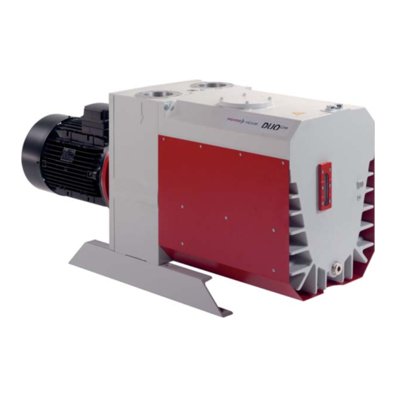
- Page 1 OPERATING INSTRUCTIONS Translation of the original instructions DUO 255, DUO 255 M Rotary Vane Pump...
-
Page 2: Table Of Contents
Table of contents Table of contents About this manual ..........3 1.1 Validity. -
Page 3: About This Manual
About this manual Validity This operating manual is for customers of Pfeiffer Vacuum. It describes the functioning of the designated product and provides the most important information for safe use of the unit. The description follows applicable EU guidelines. All information provided in this operating manual refers to the current state of the product's development. - Page 4 About this manual Pictographs Prohibition of an action to avoid any risk of accidents, the disregarding of which may result in serious accidents Warning of a displayed source of danger in connection with operation of the unit or equipment Command to perform an action or task associated with a source of dan- ger, the disregarding of which may result in serious accidents Important information about the product or this document Instructions in the...
-
Page 5: Safety
Installation and operation of accessories Pfeiffer Vacuum pumps can be equipped with a series of adapted accessories. The in- stallation, operation and maintenance of connected devices are described in detail in the operating instructions of the individual components. -
Page 6: Proper Use
● use of the vacuum pump to generate pressure ● pumping of liquids ● the use of operating fluids not specified by Pfeiffer Vacuum ● connection to pumps or units which are not suitable for this purpose according to their operating instructions ●... -
Page 7: Transport And Storage
Transport and storage Transport and storage Transport Transport instructions Remove the locking cap from the vacuum and exhaust flange immediately before con- necting! – Check the protective stainer, paying attention to the O-ring. Use only the crane eye on the top side of the pump to lift the pump. Fig. -
Page 8: Product Description
Product description Product description Product identification To correctly identify the product when communicating with Pfeiffer Vacuum, always have the information from the rating plate available and use it: ● Pump model and model number ● Serial number ● Type and amount of operating fluid ●... -
Page 9: Function
The version with magnetic coupling has as an alternative to conventional shaft feedthrough a static seal towards the outside. 2 18 17 326/248 321/245 Fig. 3: DUO 255 Vacuum flange 148 Sight glass Exhaust flange 321 Connection temperature sensor Support... -
Page 10: Installation
Installation Installation Setting up the pump Installation location Observe the following requirements when setting up the pump: ● Consider the load-bearing capacity of the installation site. ● Maximum installation altitude 2000 m (above mean sea level) ● Permissible ambient temperature: +12 ... 40°C ●... -
Page 11: Connecting The Exhaust Side
Installation Connecting the exhaust side CAUTION High pressure in the exhaust line! Danger of damage to the seals and danger of the pump bursting. Install the line without shut-off valves on the exhaust side. If there is danger of a build-up of excess pressure (> 1500 hPa abs.) in the lines, ob- serve all official accident prevention safety regulations. - Page 12 Installation Three-phase motor The three-phase current motor circuit The connections U1 - L2, V1 - L1 and W1 - L3 result in a clockwise rotation of the motor shaft as seen looking towards the motor fan. Delta Connection The three coils are connected in series with the connection point connected to the mains. The voltage of each coil is the same as the mains voltage whereas the mains current is the cube root of the coil current.
- Page 13 Installation With PTC temperature sensors (3PTC) Pump motors equipped with PTC temperature sensors (3PTC) in the stator windings can be connected to a PTC resistor tripping device for protection against overload. Other ap- proved motor temperature monitoring can be used also by the operator. Tripping devices store the shutdown event and need to be manually switched back on again via the integrated RESET button or via the external RESET S3.
-
Page 14: Filling Up The Operating Fluid
NOTICE Use approved operating fluids only! The use of operating fluids that have not been approved by Pfeiffer Vacuum shall result in a limited warranty. In such cases, it is not possible to guarantee that product-specific performance data will be achieved. -
Page 15: Operations Monitoring (Option)
Installation Operations monitoring (Option) For operations monitoring a pressure switch can be installed on the side of the support. In case of a malfunction, e. g. pressure drop or when the pump is at rest, the contact of the pressure switch opens. The signal can be used to control external valves. Parameter Oil pressure switch Protection category IP 55... -
Page 16: Operation
Operation Operation Before switching on the pump Check the operating fluid level in the sight glass. Compare the voltage and frequency information on the rating plate with the mains volt- age and frequency values. Check that the exhaust connection allows free flow (max. permissible pressure 150 hPa absolute). -
Page 17: Pumping Condensable Vapours
Operation Pumping condensable vapours Should the process gases contain condensable gases, the rotary vane pump must be operated with gas ballast (i.e. with an open gas ballast valve). NOTICE Bad final vacuum and damage to the pump! Danger of condensation and corrosion due to exceeding the water vapour compatibility during operation without gas ballast or in case of insufficient supply of flushing gas. - Page 18 Operation NOTICE Flushing gas pressure higher than allowed endangers the operational reliability of the pump. The power input of the pump, the temperature and the ejection of operating fluid will in- crease. Observe the maximum permissible flushing gas pressure. ...
-
Page 19: Switching Off The Pump
Operation Switching off the pump The pump can be switched off in any pressure range. Rotary vane pumps have an integrated safety valve on the intake side. If the differential pressure between the exhaust side and the intake side is 250 hPa, then the valve clos- es automatically and vents the pump when the pump is switched off. -
Page 20: Maintenance
Maintenance Maintenance Precautions WARNING Danger of injury from moving parts! After power failure or motor shutdown due to overheating, the motor may restart auto- matically. Secure the motor so that it cannot be switched on while any work is being performed on the pump. -
Page 21: Changing The Operating Fluid
Checklist for inspec- Certain maintenance and overhaul work should only be performed by Pfeiffer Vacuum Service (PV). Pfeiffer Vacuum will be released from all warranty and liability claims if the tion, maintenance required, below listed, intervals are exceeded or maintenance or overhaul procedures and overhaul are not performed properly. - Page 22 Fill up with operating fluid and check the filling level (see p. 14, chap. 5.5). Request safety data sheets for operating fluids and lubricants from Pfeiffer Vacuum or download at www.pfeiffer-vacuum.com. Dispose of operating fluid according to the local regulations.
-
Page 23: Cleaning And Re-Setting The Silencer
Maintenance Checking the oil filter The oil filter described here is integrated into the pump‘s oil circulation. Alternative, an additional external oil filter can be used. NOTICE Also check and clean if necessary the oil filter every time you change the oper- ating fluid. - Page 24 Maintenance Dismantling 334/ Fig. 14: Dismantle silencer Support stand Valve spindle 293 Screws Casing Flange 327 Operating fluid filler screw Cover 242 O-ring 332 Screws Baffle plate 264 O-ring 334 Hexagon nut Oil filter 292 Screws 346 Washer Valve housing ...
-
Page 25: Changing The Gas Ballast Filter
Maintenance Slowly open valve spindle 72 (1/2 to 1 rotation) until the oil hammer noise disappears. Screw in operating fluid filler screw 327. Changing the gas ballast filter The greater the contamination, the lower the filter air throughput and the greater the risk of condensation and corrosion within the pump. -
Page 26: Assembling The Motor And Coupling
Maintenance Assembling the motor and coupling Crown gear coupling When performing installation work on the coupling, it is important to observe the instal- lation instructions of the coupling manufacturer: www.ktr.com/de/index/service/montageanleitung.htm NOTICE Damage to motor bearings Blows or pressure when mounting the coupling half can damage the motor bearings. ... - Page 27 302.5 208* 302.2 302.5 * Teile 208/290 nur für DUO 255 M gültig * parts 208/290 only valid for DUO 255 M Fig. 17: Dismantling/assembling the drive motor at pumps with magnetic coupling Secure motor with chain hoist. Remove gas ballast valve 115 from the pump and absorb the operating fluid under- neath.
-
Page 28: Decommissioning
Replace the radial shaft sealing rings and further elastomer parts. Replace bearings at pumps with anti-friction bearings. Follow the maintenance instructions and inform Pfeiffer Vacuum. Disposal Products or parts thereof (mechanical and electrical components, operating fluids, etc.) may cause environmental burden. -
Page 29: Malfunctions
Thermal protection switch has re- Detect and fix cause of overheating; allow sponded pump to cool off if necessary. Pump system dirty Clean pump; contact Pfeiffer Vacuum Ser- vice if necessary. Pump system damaged Clean and overhaul pump; contact Pfeiffer Vacuum Service if necessary. - Page 30 NOTICE Service work should be carried out by a qualified person only! Pfeiffer Vacuum is not liable for any damage to the pump resulting from work carried out improperly. Take advantage of our service training programs; additional information at www.pfei- ffer-vacuum.com.
-
Page 31: Service
The following steps are necessary to ensure a fast, smooth servicing process: Download the forms "Service Request" and "Declaration on Contamination". Fill out the "Service Request" form and send it by fax or e-mail to your Pfeiffer Vacuum service address. -
Page 32: Spare Parts
258, 260, 280, 282, 287, 288, 294, 296, 312, 338 Pumping system, P3 DUO 255 M PK E03 050 -U 22, 23, 24, 25, 26, 27, 28, 29, 30, 31, 32, 33, 34, 36, 37, 38, 39, 41, 42, 43, 44, 48,... - Page 33 Spare parts Exploded view DUO 255, pump complete 102/ (106)
- Page 34 Spare parts Cover 172 Washer 269 O-ring (for revision index "A") Support stand 173 Coupling set 270 Flat seal Casing 176 Stud screw for coupling 272 Stud screw Sealing, casing 200 Pipe 273 Stud screw 201 Oil pipe, 12 Flange 284 Allen head screw 203 Oil pipe, ...
- Page 35 295 (DUO 255 M) 293 (DUO 125 M) 142 (DUO 255 M) 143 (DUO 125 M) 301 (DUO 255 298 (DUO 125 Fig. 18: DUO 255 M with magnetic coupling Cover 192 Magnetic coupling 293 Allen head screw 140 Centering flange 193 Can...
- Page 36 Spare parts Exploded view DUO 255, pumping system 34 23 Support plate Bearing cover PLate spring of non-return valve Set screw Silencer, complete Needle bearing Gear wheel, driven 225 Elbow union G 1/2" Cover ring for needle bearing Gear wheel, treibend...
- Page 37 Spare parts Exploded view DUO 255, vacuum safety valve 84/85/86: mit Loctite 222 kleben/ apply Loctite 222 Oil filter Circlip 100 Cover Flange ring Valve stem Pos. 86 + 262 Valve housing Buffer 262 O-ring Valve cover Valve plate 264 O-ring...
-
Page 38: Accessories
PK 005 875 -T D1, synthetic diester based oil, 5 l PK 005 876 -T D1, synthetic diester based oil, 20 l PK 005 877 -T Further detailed accessories are contained in the Pfeiffer Vacuum printed or Online Cat- alogue. -
Page 39: Technical Data And Dimensions
Technical data and dimensions 13 Technical data and dimensions 13.1 General Conversion table: pressure units mbar Torr mm Hg mbar 1 · 10 0.75 1000 1 · 10 1000 0.01 1 · 10 0.01 1 · 10 7.5 · 10 1 ·... -
Page 40: Technical Data
Operating fluid filling 25 l Weight 360 kg Cooling method, standard Table 1: Typical ultimate pressure according to PNEUROP Parameter Duo 255 M Flange (in) DN 100 ISO-F Flange (out) DN 100 ISO-F Pumping speed at 50 Hz 250 m... -
Page 41: Dimensions
Technical data and dimensions 13.3 Dimensions (1494 ) 1407 G1/2 M14 x 1,5 318,5 M8 - 17tief (8x) DN 100 ISO-F (...): DUO 255 M G 3/4 (2x) Fig. 19: DUO 255, DUO 255 M... -
Page 42: Declaration Of Conformity
● Electromagnetic Compatibility 2014/30/EU ● Restriction of the use of certain Hazardous Substances 2011/65/EU The agent responsible for compiling the technical documentation is Mr. Sebastian Ober- beck, Pfeiffer Vacuum GmbH, Berliner Straße 43, 35614 Aßlar. DuoLine™ DUO 255 Harmonised standards and national standards and specifications which have been ap-... - Page 43 VACUUM SOLUTIONS FROM A SINGLE SOURCE Pfeiffer Vacuum stands for innovative and custom vacuum solutions worldwide, technological perfection, competent advice and reliable service. COMPLETE RANGE OF PRODUCTS From a single component to complex systems: We are the only supplier of vacuum technology that provides a complete product portfolio.
Need help?
Do you have a question about the DUO 255 and is the answer not in the manual?
Questions and answers