Table of Contents
Advertisement
Quick Links
Advertisement
Table of Contents
Troubleshooting

Related Manuals for Dynojet 250i


Summary of Contents for Dynojet 250i
- Page 2 ©2014-2017 Dynojet Research, Inc. All Rights Reserved. Installation Guide for Above Ground Model 250i Motorcycle Dynamometers. This manual is copyrighted by Dynojet Research, Inc., hereafter referred to as Dynojet, and all rights are reserved. This manual, and the software described in it, is furnished under license and may only be used or copied in accordance with the terms of such license.
-
Page 3: Table Of Contents
Network Connections ..........1-15 Above Ground Model 250i Motorcycle Dynamometer Installation Guide... - Page 4 Installing the High Pressure Blowers ........3-33 Above Ground Model 250i Motorcycle Dynamometer Installation Guide...
- Page 5 ..........5-14 Version 4 Above Ground Model 250i Motorcycle Dynamometer Installation Guide...
- Page 6 ............Index-i Above Ground Model 250i Motorcycle Dynamometer Installation Guide...
-
Page 7: Warnings
Dynojet reserves the right to revise this publication and to make changes from time to time in the content hereof without obligation of Dynojet to notify any person of such revision or changes. - Page 8 To avoid ESD damage, always practice good ESD control precautions when servicing the dynamometer. Dynojet designs its dynamometers to be very tolerant of static shocks by the users, but the electronics are vulnerable when the electronics are exposed.
- Page 9 Do not repair or replace any part of the dynamometer or attempt any servicing unless specifically recommended in published user-repair instructions that you understand and have the skills to carry out. Version 4 Above Ground Model 250i Motorcycle Dynamometer Installation Guide...
- Page 11 Whether you are new to the benefits of a chassis dynamometer or an experienced performance leader, the repeatability and diagnostic tools of Power Core software and a Dynojet dynamometer will give you the professional results you require.
-
Page 12: Introduction
This appendix describes power requirements and installation instructions. EEC K This appendix describes the procedures for installing the EEC finger guards and door safety switch. ORQUE ALUES This appendix describes standard and metric torque values. Above Ground Model 250i Motorcycle Dynamometer Installation Guide... -
Page 13: Technical Support
Dynojet provides state of the art technical support, on-line shopping, and press releases about our latest product lines. Try our remote support assistance or watch one of our informative videos. Access the electronic version of this guide along with additional accessory guides, software guides, and the latest technical bulletins at www.dynojet.com/downloads. -
Page 14: Your Dyno Room
This section is not meant to imply that a dyno room is essential to repeatable results on a Dynojet dynamometer. However, a dyno room with an engine cooling intake fan, exhaust extraction, and noise reduction capabilities can add a new dimension to your shop. -
Page 15: Dynamometer Specifications And Requirements
ATTERY EQUIREMENTS Your 200i/250i dyno is designed to carry a group 24 deep-cycle discharge series battery for operating the starter, power carriage, and optional wheel clamp. The typical dimensions for this series of batteries are 27 cm long by 17 cm wide by 23 cm tall (10.625-inches by 6.75-inches by 9.125-inches). - Page 16 C H A P T E R 1 Dynamometer Specifications and Requirements Figure 1-1: Model 200i Dimensions Above Ground Model 250i Motorcycle Dynamometer Installation Guide...
- Page 17 S P E C I F I C AT I O N S A N D O P E R AT I N G R E Q U I R E M E N T S Dynamometer Specifications and Requirements Figure 1-2: Model 250i Dimensions Version 4 Above Ground Model 250i Motorcycle Dynamometer Installation Guide...
-
Page 18: Compressed Air
1 free 10/100 Mbps 1 free 100Mbps RJ45 Port or Wireless RJ45 Ethernet Port External Media CD-Rom Drive CD-Rom Drive Printer Printer, if prints are needed Color printer, if prints are needed Above Ground Model 250i Motorcycle Dynamometer Installation Guide... -
Page 19: Electrical Requirements
(2,500 lbs.) to lift the dyno off the crate and into position in your dyno room. You will also need a pair of straps capable of supporting the uncrated dyno. Dynojet recommends using single loop style straps. Using lift straps with bare forks is no OSHA compliant. -
Page 20: Grounding Requirements
NTERNET CCESS Dynojet recommends you have a phone close to the dyno to call for assistance in an emergency. You may also wish to contact Dynojet to troubleshoot your dyno. Internet access on your computer is desirable for contacting Dynojet and downloading new information and updates. -
Page 21: Model 200I Motorcycle Dynamometer
Breaker Hand Wheel Power Cord Control Panel Interface DynoWare RT houses the main power breaker, eddy current brake driver, and battery disconnect Air Connector Figure 1-3: Model 200i Dyno Version 4 Above Ground Model 250i Motorcycle Dynamometer Installation Guide 1-11... -
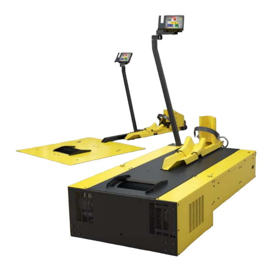
Page 22: Model 250I Motorcycle Dynamometer
Power Carriage MC157 Tire Carriage Tie-down Loop used to secure the motorcycle to dyno Drum precision balanced Air Brake and knurled Air Pump Assembly Figure 1-4: Model 250i With Optional Accessories Above Ground Model 250i Motorcycle Dynamometer Installation Guide 1-12... -
Page 23: Dynoware Rt Electronics
DynoWare RT electronics can be found in the Power Core Help. DynoWare RT eddy current main module brake driver air fuel ratio speed pickup module Figure 1-5: DynoWare RT Electronics Version 4 Above Ground Model 250i Motorcycle Dynamometer Installation Guide 1-13... - Page 24 Do not press this button unless drum 2 speed inputs and Instructions instructed to do so by a Dynojet digital brake outputs. Technician. This button may need to be pressed to update the device. Above Ground Model 250i Motorcycle Dynamometer Installation Guide 1-14...
-
Page 25: Network Connections
ETWORK ONNECTIONS The Dynojet DynoWare RT dyno electronics connects to your computer directly or over a Local Area Network. If you have an existing network, connect the DynoWare RT main module to a router or a network switch on your network. If you do not have an existing network, you can create a network for the DynoWare RT by connecting the main module to a router. - Page 27 • Tire Carriage Installation, page 2-38 • Side and Top Cover Installation, page 2-42 • Load Cell Calibration, page 2-45 • Ramp Bracket, page 2-50 • Ground Hook Installation, page 2-53 • Zip Tube, page 2-54 Above Ground Model 250i Motorcycle Dynamometer Installation Guide...
-
Page 28: Unpacking And Inspecting The Dyno
UNPACKING AND INSPECTING THE DYNO When you receive your dyno, examine the exterior of the shipping container for any visible damage. If damage is detected at this stage, contact the shipper or Dynojet before proceeding. Use the following steps to unload your dyno. You will need to provide equipment capable of lifting a minimum of 1,133.98 kg (2,500 lbs.) to move the crated dyno into... - Page 29 Remove the six 1/4-inch screws securing the center panel on the dyno and remove the center panel. Note: Dynojet recommends using a T30 Torx driver (Snap-On PFTx30E) to remove the 1/4-inch screws. Remove the tire stop, tire lock, and hardware from the middle of the dyno.
- Page 30 Remove the two top screws securing each side drum cover to the dyno and set aside. top drum cover side drum cover side drum cover D 038 Figure 2-3: Remove the Top Drum Cover Above Ground Model 250i Motorcycle Dynamometer Installation Guide...
- Page 31 D 039 access holes in drum bulkhead (only two visible from this view) Figure 2-4: Remove the Side Drum Covers Version 4 Above Ground Model 250i Motorcycle Dynamometer Installation Guide...
- Page 32 P/N 42900000 pickup (2) P/N 76950201 secondary inductive cable harness wrap kit P/N 43400000 pickup (2) P/N 76950203 cable clamp (7) cable, wheel clamp P/N 43428232 P/N 76950307 optional accessory Above Ground Model 250i Motorcycle Dynamometer Installation Guide...
- Page 33 P/N 63310902 P/N 76950791 not included if you ordered the optional wheel clamp on dyno air fuel ratio cable, CAN dyno user, 15' assembly P/N 76950798 P/N 64100008 optional accessory Version 4 Above Ground Model 250i Motorcycle Dynamometer Installation Guide...
- Page 34 P/N D706 extended carriage assembly P/N 71323003 wheel clamp hand wheel P/N 71329000 P/N DM150-016-006 optional accessory see page 3-27 pendant assembly bolt, 3/8-16 x 3/4" hex (4) P/N 76100007 P/N DM150-019-008 Above Ground Model 250i Motorcycle Dynamometer Installation Guide...
- Page 35 P/N 21224104 P/N 61324102 carriage clamp spacer (3) bolt, 5/16-18 x 1.5", hex (8) P/N 21224105 P/N DM150-002-003 nut block spacer washer, lock, 5/16" (8) P/N 21224106 P/N DM150-02-004 Version 4 Above Ground Model 250i Motorcycle Dynamometer Installation Guide...
-
Page 36: Dyno Installation
You will need to provide equipment capable of lifting a minimum of 1,133.98 kg (2,500 lbs.) to lift the dyno off the crate and into position in your dyno room. You will also need a pair of straps capable of supporting the same weight. Dynojet recommends using a single loop style strap. - Page 37 Note: While the dyno is supported by the forklift and before it is placed in your dyno room, the power cable must be routed through the front of the dyno. Figure 2-7: Lift the Dyno off the Crate Version 4 Above Ground Model 250i Motorcycle Dynamometer Installation Guide 2-11...
- Page 38 MC076A cut away view from inside dyno opening in dyno frame jam nut knurled nut inside dyno strain relief around outside dyno power cord Figure 2-8: Route the Power Cable Above Ground Model 250i Motorcycle Dynamometer Installation Guide 2-12...
-
Page 39: Battery Installation
Battery Installation BATTERY INSTALLATION The model 200i/250i dyno is designed to carry a group 24 deep-cycle discharge series battery for operating the starter, optional power carriage, and optional wheel clamp. The typical dimensions for this series of batteries are 27 cm long by 17 cm wide by 23 cm tall (10.625-inches by 6.75-inches by 9.125-inches). -
Page 40: Pickup Card Installation
Figure 2-10: Install the Pickup Card Above Ground Model 250i Motorcycle Dynamometer Installation Guide 2-14... -
Page 41: Eddy Current Brake Installation
“Secure the Dyno and Brake Module to the Floor” on page 2-25. You will need to provide equipment capable of lifting the eddy current brake off the crate and into position in your dyno room. You will also need a pair of straps. Dynojet recommends using continuous nylon loop style straps. - Page 42 Red Head, 3/8" (2) cable, IR temp sensor P/N 37513200 P/N 76950569 installation tool, Red Head bolt, 3/8-16 x 1", hex (2) anchor P/N DM150-019-012 P/N 37518200 driveline assembly P/N 62240070 Above Ground Model 250i Motorcycle Dynamometer Installation Guide 2-16...
- Page 43 RECORD Be sure you record the eddy current brake number on the inside cover of this manual. top cover eddy current brake number Figure 2-12: Remove the Covers Version 4 Above Ground Model 250i Motorcycle Dynamometer Installation Guide 2-17...
- Page 44 Figure 2-13: Identifying Left or Right Side Brake Set Up apply force using hammer and punch shaft apply force using hammer and punch Figure 2-14: Remove the Key Above Ground Model 250i Motorcycle Dynamometer Installation Guide 2-18...
- Page 45 EB238 lifting eye remove bolts, washers, and lifting eye nuts from dyno frame Figure 2-15: Move the Brake Next to the Dyno Version 4 Above Ground Model 250i Motorcycle Dynamometer Installation Guide 2-19...
-
Page 46: Installing The Eddy Current Brake
Be sure to follow the safety requirements specific to your country. Insert the key into the keyway. Use a c-clamp to press the key in, if necessary. key way on dyno shaft EB239 retarder connector plate Figure 2-16: Install the Key Above Ground Model 250i Motorcycle Dynamometer Installation Guide 2-20... - Page 47 Once aligned, tighten all retarder connector plate bolts and nuts. retarder connector plate EB240 three bolts not visible from this view Figure 2-17: Secure the Retarder Connector Plate and Starter Brace Version 4 Above Ground Model 250i Motorcycle Dynamometer Installation Guide 2-21...
- Page 48 Replace the existing set screws on the coupler with the thread-lock set screws provided. 10 Tighten the coupler set screws. dyno shaft brake shaft set screw Figure 2-19: Tighten the Set Screws Above Ground Model 250i Motorcycle Dynamometer Installation Guide 2-22...
- Page 49 Remove the two bolts and nuts securing the existing bar on the eddy current brake and remove the bar. Set the bolts and nuts aside. Figure 2-20: Remove the Existing Bar Version 4 Above Ground Model 250i Motorcycle Dynamometer Installation Guide 2-23...
- Page 50 Refer to “Cable Routing” on page 2-28 for more information on routing the load cell cable. Refer to “Load Cell Calibration” on page 2-45 for more information on calibrating the load cell.l load cell load cell cable Figure 2-22: Install the Load Cell Above Ground Model 250i Motorcycle Dynamometer Installation Guide 2-24...
-
Page 51: Secure The Dyno And Brake Module To The Floor
Secure the Dyno and Brake Module to the Floor SECURE THE DYNO AND BRAKE MODULE TO THE FLOOR Dynojet recommends you anchor the eddy current brake, along with the dyno, to the floor in your dyno room using concrete anchors. You will want to drill the holes and secure the dyno before adding any accessories or replacing the covers on your dyno. -
Page 52: Support Arm And Monitor Tray Installation
Insert a plastic cap in both ends of each arm. Check for clearance between the monitor arm and motorcycle, walls, ceiling, etc. Note: Dynojet does not recommend placing the computer CPU on the monitor/keyboard tray since vibration can cause damage to the computer. - Page 53 Support Arm and Monitor Tray Installation poly washer second arm monitor tray poly washer first arm poly washer support arm MA021 Figure 2-24: Install the Support Arm and Monitor Tray Version 4 Above Ground Model 250i Motorcycle Dynamometer Installation Guide 2-27...
-
Page 54: Cable Routing
H - 76950569 IR temp sensor cable connects to the temp sensor cable to the eddy current brake driver I - 76950573 load cell cable connects the load cell to the eddy current brake driver *optional accessory Above Ground Model 250i Motorcycle Dynamometer Installation Guide 2-28... - Page 55 PCV module when connected to the DynoWare RT using the CAN Powersports cable S - 76423045 CAN termination plug connects to the last CAN cable in the CAN network cable chain Version 4 Above Ground Model 250i Motorcycle Dynamometer Installation Guide 2-29...
-
Page 56: Installing The Dynoware Rt Main Module
Attach the temp sensor cable (H) to the eddy current brake driver. 10 Attach the load cell cable (I), if present, to the eddy current brake driver. Above Ground Model 250i Motorcycle Dynamometer Installation Guide 2-30... - Page 57 22b Insert the PCV CAN termination plug (R) in the PCV module. Note: If you are not using a PCV, be sure to save the PCV CAN termination plug (R) for future use. Version 4 Above Ground Model 250i Motorcycle Dynamometer Installation Guide 2-31...
- Page 58 C H A P T E R 2 Cable Routing Figure 2-27: Routing the Cables Above Ground Model 250i Motorcycle Dynamometer Installation Guide 2-32...
- Page 59 Remove the control panel rear cover and set aside. top screw CP025 rear screws top nuts back cover screws side screw Figure 2-28: Locate the Control Panel and Remove the Back Cover Version 4 Above Ground Model 250i Motorcycle Dynamometer Installation Guide 2-33...
- Page 60 Replace the screw on the side of the cover removed earlier. Replace the two nuts on the top of the cover removed earlier. Figure 2-30: Replace the Control Panel Rear Cover Above Ground Model 250i Motorcycle Dynamometer Installation Guide 2-34...
- Page 61 Adjust the service loops to allow for easy movement of the monitor arms without pulling on the cables. control panel CP023 install control panel spindle if you did not purchase the monitor tray CP035 Figure 2-31: Install the Control Panel Version 4 Above Ground Model 250i Motorcycle Dynamometer Installation Guide 2-35...
- Page 62 Route the power carriage and wheel clamp cables through the opening in the front of the dyno. route cables through cable pass through cover Figure 2-32: Remove the Cable Pass Through Cover Above Ground Model 250i Motorcycle Dynamometer Installation Guide 2-36...
- Page 63 Secure the cable pass through cover to the dyno with the two screws removed earlier. cable pass through cover W 016 3-pin wheel clamp cable 2-pin power carriage cable Figure 2-33: Routing Wheel Clamp and Power Carriage Cables Version 4 Above Ground Model 250i Motorcycle Dynamometer Installation Guide 2-37...
-
Page 64: Tire Carriage Installation
Bolt, 3/8-16 x 1/2", Bh-Flange (8) • 61324102 Nut Block • 63310902 Tire Stop • 71323002 Standard Carriage • DM150-002-003 Lock Washer, 5/16" (8) • DM150-002-004 Bolt, 5/16-18 x 1.5", Hex (8) • DM150-016-006 Hand Wheel Above Ground Model 250i Motorcycle Dynamometer Installation Guide 2-38... - Page 65 Remove the four 1/4 x 20-inch button-head screws securing the bearing bracket. Remove the bearing bracket and the carriage screw. carriage screw screw bearing bracket Figure 2-35: Remove the Bearing Bracket and Carriage Screw Version 4 Above Ground Model 250i Motorcycle Dynamometer Installation Guide 2-39...
- Page 66 Note: If you ordered the power carriage accessory, refer to “Power Carriage” on page 3-35 for installation instructions. carriage nut block carriage screw hand wheel TC070 bearing bracket Figure 2-36: Install the Tire Carriage and Secure the Hand Wheel Above Ground Model 250i Motorcycle Dynamometer Installation Guide 2-40...
- Page 67 13 Secure the tire lock to the carriage using four 3/8-16 x 1/2-inch button-head flange bolts. tire lock tire stop TC071 Figure 2-37: Install the Tire Stop and Tire Lock Version 4 Above Ground Model 250i Motorcycle Dynamometer Installation Guide 2-41...
-
Page 68: Side And Top Cover Installation
Secure the eddy current brake side cover to the dyno using six of the screws you removed earlier. drum side cover brake side cover MC149 Figure 2-38: Replace the Side Covers Above Ground Model 250i Motorcycle Dynamometer Installation Guide 2-42... - Page 69 Secure the top drum cover to the dyno using the eight screws removed earlier. top drum cover MC150 Figure 2-39: Replace the Top Drum Cover Version 4 Above Ground Model 250i Motorcycle Dynamometer Installation Guide 2-43...
- Page 70 Side and Top Cover Installation Secure the eddy current brake top cover with the screws you removed earlier. eddy current brake cover EB242 Figure 2-40: Replace the Eddy Current Brake Top Cover Above Ground Model 250i Motorcycle Dynamometer Installation Guide 2-44...
-
Page 71: Load Cell Calibration
Note: There should not be anything resting on the eddy current brake or the dyno drum during this procedure. Click Next to zero the connected torque cell. Figure 2-41: Zero Calibration Window Version 4 Above Ground Model 250i Motorcycle Dynamometer Installation Guide 2-45... - Page 72 Note: Dynojet recommends you secure the calibration arm using the bolt pattern closest to the end of the arm unless space constraints in your dyno room do not allow you to.
- Page 73 T 074 Figure 2-44: Install the Calibration Arm and Weights Using the Bolt Pattern Closest to the End Version 4 Above Ground Model 250i Motorcycle Dynamometer Installation Guide 2-47...
- Page 74 Figure 2-45. weight support pin weights secure arm to brake by tightening handle T 075 Figure 2-45: Install the Calibration Arm and Weights Using the Bolt Pattern in the Center Above Ground Model 250i Motorcycle Dynamometer Installation Guide 2-48...
- Page 75 13 Remove the calibration arm and weights and click Finish. Figure 2-46: Finish Calibration Window 14 Confirm the calibration was successful. For more information refer to the Power Core Online Help. Version 4 Above Ground Model 250i Motorcycle Dynamometer Installation Guide 2-49...
-
Page 76: Ramp Bracket
Using the larger holes on the bracket, mark and drill two 3/8-inch holes in the ramp. ramp lip ramp bracket 24 inches Figure 2-47: Mark and Drill Ramp Bracket Holes Above Ground Model 250i Motorcycle Dynamometer Installation Guide 2-50... - Page 77 Remove the four 1/4-inch bolts from the rear of the drum cover. Secure the ramp bracket to the rear drum cover using the bolts you just removed. M 151 Figure 2-49: Secure the Bracket to the Drum Cover Version 4 Above Ground Model 250i Motorcycle Dynamometer Installation Guide 2-51...
- Page 78 Place the ramp on the ramp bracket slipping the bolts on the ramp through the large holes on the ramp bracket. M 152 Figure 2-50: Place the Ramp on the Dyno Above Ground Model 250i Motorcycle Dynamometer Installation Guide 2-52...
-
Page 79: Ground Hook Installation
Secure each ground hook to the floor using two 3/8-16 x 1-inch hex bolts and two 3/8-inch lock washers. approx. 152.40 cm (60.00 in.) approx. 20.00 cm (8.00 in.) approx. 96.50 cm (38.00 in.) G 009 Figure 2-51: Ground Hooks Version 4 Above Ground Model 250i Motorcycle Dynamometer Installation Guide 2-53... -
Page 80: Zip Tube
Pull the cable wrap tool through the zip tube along the length of the cables. guide body zip tube cable wrap tool end of cables Figure 2-53: Secure the Cable(s) Into the Zip Tube Above Ground Model 250i Motorcycle Dynamometer Installation Guide 2-54... -
Page 81: Accessories
This chapter discusses the various optional accessories that are available for the Dynojet Motorcycle Dynamometer (dyno) to meet your individual needs. All of these options can be added at the factory at the time of original dyno purchase, or purchased separately and added at any time thereafter. -
Page 82: Main Dyno Power
Disconnect the power plug to ensure all power has been removed from the dyno before performing certain installation procedures. power plug MC153 main breaker Figure 3-1: Main Dyno Power Above Ground Model 250i Motorcycle Dynamometer Installation Guide... -
Page 83: Air Brake
Attach the two-pin connector to the DynoWare RT main box. Attach the flat four-pin connector to P7 on the CPI board. A 128 P7 on the CPI board Figure 3-2: Route the Air Brake Cable Version 4 Above Ground Model 250i Motorcycle Dynamometer Installation Guide... - Page 84 You will need to provide an air hose nipple (1/4-inch NPT) to connect your clean, dry shop air supply (60 psi, 415 kilopascal, max constant line pressure) to the dynamometer. Figure 3-3: Connect the Air Hose Above Ground Model 250i Motorcycle Dynamometer Installation Guide...
-
Page 85: Installing The Emergency Stop Sticker
Remove the four screws on the back of the cover and set aside. Remove the control panel rear cover and set aside. top screw top nuts side screw rear screws Figure 3-4: Remove the Control Panel Rear Cover Version 4 Above Ground Model 250i Motorcycle Dynamometer Installation Guide... - Page 86 Figure 3-5: Remove the Button Board Unscrew the black switch body nut and remove the switch body. Set the nut and switch body aside. switch body switch body nut Figure 3-6: Remove the Switch Body Above Ground Model 250i Motorcycle Dynamometer Installation Guide...
- Page 87 A C C E S S O R I E S Air Brake Place the emergency stop sticker over the dyno shutdown sticker. place emergency stop sticker here CP015 Figure 3-7: Place the Emergency Stop Sticker Version 4 Above Ground Model 250i Motorcycle Dynamometer Installation Guide...
- Page 88 Figure 3-8: Replace the Emergency Stop Button Secure the Button board to the control panel using the four screws removed earlier. button board screw Figure 3-9: Secure the Button Board Above Ground Model 250i Motorcycle Dynamometer Installation Guide...
-
Page 89: Air Brake Final Adjustments And Tests
Refer to “Adjusting the Brake Pad Clearance” on page 3-15 for instructions on adjusting the brake pad clearance. Version 4 Above Ground Model 250i Motorcycle Dynamometer Installation Guide... - Page 90 Refer to Figure 3-3 on page 3-4. Remove the hairpin cotter and loosen the castle nut until the pads clear the rotor. outboard brake pad adjust castle nut remove hairpin cotter Figure 3-11: Loosen the Castle Nut Above Ground Model 250i Motorcycle Dynamometer Installation Guide 3-10...
- Page 91 The spring is located on the drum side of the brake assembly. Note: For clarity, the drum is not shown. nut, washer, and spring bolt nut, washer, and spring bolt Figure 3-12: Remove the Brake Spring Version 4 Above Ground Model 250i Motorcycle Dynamometer Installation Guide 3-11...
- Page 92 Figure 3-13: Remove the Brake Caliper Stop Remove the hairpin cotter from the bottom clevis pin located on the front of the air brake assembly. bottom clevis pin hairpin cotter Figure 3-14: Remove the Bottom Hairpin Cotter Above Ground Model 250i Motorcycle Dynamometer Installation Guide 3-12...
- Page 93 Figure 3-15: Remove the Bottom Pin and the Top Hairpin Cotter Remove the top clevis pin. top clevis pin Figure 3-16: Remove the Top Clevis Pin Version 4 Above Ground Model 250i Motorcycle Dynamometer Installation Guide 3-13...
- Page 94 18 Adjust the brake pad clearance. Refer to“Adjusting the Brake Pad Clearance” on page 3-15 for complete instructions. 19 Replace the top and right side covers. Refer to page 2-4. 20 Connect your shop air. Above Ground Model 250i Motorcycle Dynamometer Installation Guide 3-14...
- Page 95 If the pads touch the rotor during a run, the information provided by the dyno will be inaccurate. brake adjusting shim rotor inboard brake pad brake caliper stop bolts Figure 3-18: Adjust Brake Pad Clearance Version 4 Above Ground Model 250i Motorcycle Dynamometer Installation Guide 3-15...
-
Page 96: Air Fuel Ratio Module
To ensure accurate readings, pump maintenance should be performed every six months, or sooner, depending on usage. Refer to the Air Fuel Ratio Module Installation and User Guide for more information. Above Ground Model 250i Motorcycle Dynamometer Installation Guide 3-16... -
Page 97: Extended Carriage
P/N 21224104 P/N 61324102 carriage clamp spacer (3) bolt, 5/16-18 x 1.5", hex (8) P/N 21224105 P/N DM150-002-003 nut block spacer washer, lock, 5/16" (8) P/N 21224106 P/N DM150-02-004 Version 4 Above Ground Model 250i Motorcycle Dynamometer Installation Guide 3-17... -
Page 98: Installing The Extended Carriage Support Bracket
Using a straight edge, line the top of the support bracket with the top of the dyno chassis. Tighten all six screws. extended carriage support bracket T 075 Figure 3-19: Install the Extended Carriage Support Bracket Above Ground Model 250i Motorcycle Dynamometer Installation Guide 3-18... - Page 99 Note: If your support bracket does not have holes, use the strap as a template to drill them. strap support bracket Figure 3-20: Secure the Strap to the Dyno and Support Bracket Version 4 Above Ground Model 250i Motorcycle Dynamometer Installation Guide 3-19...
-
Page 100: Installing The Extended Carriage
Remove the four 1/4 x 20-inch button-head screws securing the bearing bracket to the carriage. Remove the bearing bracket and the carriage screw. carriage screw screw bearing bracket Figure 3-22: Remove the Bearing Bracket and Carriage Screw Above Ground Model 250i Motorcycle Dynamometer Installation Guide 3-20... - Page 101 Note: If you ordered the power carriage accessory, refer to “Power Carriage” on page 3-35 for installation instruction. extended carriage nut block carriage screw T 077 hand wheel carriage clamp bearing bracket Figure 3-23: Install the Extended Carriage Version 4 Above Ground Model 250i Motorcycle Dynamometer Installation Guide 3-21...
- Page 102 10 Install the two rear carriage clamps and spacers using two 5/16-18 x 1.5-inch bolts and two 5/16-inch lock washers,. bolt washer carriage clamp spacer T 078 Figure 3-24: Install the Rear Carriage Clamps Above Ground Model 250i Motorcycle Dynamometer Installation Guide 3-22...
- Page 103 12 Secure the tire lock to the carriage using four 3/8-16 x 1/2-inch button-head flange bolts. tire lock tire stop T 079 Figure 3-25: Install the Tire Stop and Tire Lock Version 4 Above Ground Model 250i Motorcycle Dynamometer Installation Guide 3-23...
-
Page 104: Folding Ramp
This section will walk you through removing the ramp from the crate and installing the ramp on model 200i and 250i motorcycle dynos. To ensure safety and accuracy in the procedures, perform the procedures as they are described. - Page 105 Folding Ramp Remove the crate braces. crate braces Figure 3-27: Remove the Crate Braces Remove the 2x2 brace securing the ramp down. 2x2 brace Figure 3-28: Remove the 2x2 Brace Version 4 Above Ground Model 250i Motorcycle Dynamometer Installation Guide 3-25...
- Page 106 Folding Ramp Fold the ramp up. Remove the front crate panel. Remove the braces. fold ramp up braces front crate panel Figure 3-29: Fold Ramp Up and Remove Front Crate Panel Above Ground Model 250i Motorcycle Dynamometer Installation Guide 3-26...
- Page 107 (not visible from this view) Figure 3-30: Remove the Bolts and Washers Securing the Ramp to the Crate Version 4 Above Ground Model 250i Motorcycle Dynamometer Installation Guide 3-27...
- Page 108 C H A P T E R 3 Folding Ramp Remove the ramp by sliding it from the front of the crate. Dynojet recommends using two people to remove the ramp from the crate. Figure 3-31: Remove the Ramp from the Crate...
- Page 109 Figure 3-32: Lower the Ramp Version 4 Above Ground Model 250i Motorcycle Dynamometer Installation Guide 3-29...
- Page 110 Remove the four 1/4-inch button-head bolts from the top of the dyno. Remove the two 3/8-inch button-head bolts from the back of the dyno. remove four top bolts remove two back bolts Figure 3-33: Remove the Bolts from the Dyno Above Ground Model 250i Motorcycle Dynamometer Installation Guide 3-30...
- Page 111 Secure the sides of the ramp to the dyno using the two button-head bolts removed earlier. secure with four top bolts secure with two back bolts (only one visible) Figure 3-34: Secure the Ramp to the Dyno Version 4 Above Ground Model 250i Motorcycle Dynamometer Installation Guide 3-31...
-
Page 112: High Pressure Blower
(2) P/N 63400001 P/N 26215521 clamp lever, 3/8-16 x 3/4" cable, blower assembly (4) power (2) P/N 35712991 P/N 76950301 clamp lever, 3/8-16 x 1.5" blower assembly (2) (2) P/N 35712992 Above Ground Model 250i Motorcycle Dynamometer Installation Guide 3-32... -
Page 113: Installing The High Pressure Blowers
Risk of injury. Eye protection required. Be aware of debris from blowers. Be sure the blowers are free and clear of any obstruction. The blowers can run at any time once the cord is plugged into a power source. Version 4 Above Ground Model 250i Motorcycle Dynamometer Installation Guide 3-33... - Page 114 1/8-inch thick poly washer 1/4-inch thick poly washer lower arm has longer pin 1.5-inch clamp lever power cord power source on from blower dyno chassis Figure 3-35: Install the High Pressure Blowers Above Ground Model 250i Motorcycle Dynamometer Installation Guide 3-34...
-
Page 115: Power Carriage
1/4-20 x 5/8", ph, power carriage mount P/N 21624104 torx (4) P/N 36561045 coupler spider power carriage motor P/N 32431000 assembly P/N 66212120 coupler jaw, 5/8" P/N 32431001 Version 4 Above Ground Model 250i Motorcycle Dynamometer Installation Guide 3-35... -
Page 116: Removing The Hand Wheel
Loosen the set screw on the hand wheel and remove the hand wheel. Using a 7/16-inch wrench, remove the two bolts securing the flange bearing. flange bearing bolt hand wheel Figure 3-36: Remove the Hand Wheel Above Ground Model 250i Motorcycle Dynamometer Installation Guide 3-36... -
Page 117: Installing The Power Carriage
If the motor mount is already installed, skip this step and continue. Note: The flange bearing must be facing so the grease zerk is accessible (facing down). Note: Dynojet recommends using a 1/4-inch ratchet drive with an extension and a 7/16-inch shallow socket to secure the flange bearing bolts. motor mount... - Page 118 Secure the motor assembly cover to the motor mount with four 1/4-20 x 1/2-inch button-head screws. power carriage cable strain relief coupler spider motor assembly cover Figure 3-38: Assemble the Power Carriage Above Ground Model 250i Motorcycle Dynamometer Installation Guide 3-38...
-
Page 119: Wheel Clamp
Secure the wheel clamp to the carriage using four 3/8-16 x 1/2-inch bolts, lock washers and flat washers. wheel clamp WC004B Figure 3-40: Secure the Wheel Clamp to the Carriage Version 4 Above Ground Model 250i Motorcycle Dynamometer Installation Guide 3-39... - Page 120 Plug the wheel clamp cable into the connector on the wheel clamp motor. strain relief wheel clamp cable WC005A Figure 3-41: Install Wheel Clamp Strain Relief Replace the wheel clamp cover. cover WC006A Figure 3-42: Replace the Wheel Clamp Cover Above Ground Model 250i Motorcycle Dynamometer Installation Guide 3-40...
-
Page 121: Final Adjustments And Tests
Press and hold the right hand wheel clamp button then press the left hand button to open the clamp. Refer to “Using the Wheel Clamp” on page 4-7 for more information on using the control panel. Version 4 Above Ground Model 250i Motorcycle Dynamometer Installation Guide 3-41... -
Page 123: Control Panel Interface Operation
This chapter is divided into the following categories: • Introduction, page 4-2 • Basic Control Panel Operation, page 4-3 • Power Distribution Assembly, page 4-9 • Maintenance and Troubleshooting, page 4-10 Above Ground Model 250i Motorcycle Dynamometer Installation Guide... -
Page 124: Introduction
The control panel interface (CPI) consists of a main control board which is mounted internal to the 200i/250i motorcycle dyno or in an external box for a pit dyno or retrofit. This board provides switching and control of many functions within the dyno. -
Page 125: Basic Control Panel Operation
The graphics on the control panel are grouped together according to function and color coded for ease of identification. A description of the functions and displays follows: status indicator light Figure 4-1: Control Panel Features Version 4 Above Ground Model 250i Motorcycle Dynamometer Installation Guide... -
Page 126: Using The Emergency Stop/Dyno Shutdown
During an E-Stop condition the Status Indicator light will be flashing with two short blinks on and long pause off. Above Ground Model 250i Motorcycle Dynamometer Installation Guide... -
Page 127: Using The High Pressure Blowers
CPI output is on. The blower outlets on the front of the dyno are designed to only work with Dynojet provided blowers. Connecting other electrical loads or other blowers to the outlets on the dyno may damage the dyno and void the warranty. -
Page 128: Using The Power Carriage
Press and hold the green starter button until the drum reaches maximum speed. Release the green starter button. Use the momentum of the drum to start the bike. Note: Do not re-engage the starter while the drum is turning. Above Ground Model 250i Motorcycle Dynamometer Installation Guide... -
Page 129: Using The Status Indicator
Risk of injury. Be sure the wheel clamp is free and clear of any obstruction. Do not operate the dyno if the wheel clamp indicator light is not on steady. Version 4 Above Ground Model 250i Motorcycle Dynamometer Installation Guide... - Page 130 The status indicator light will be blinking to indicate the wheel is not secured and a dyno run should not be attempted. Continue to open the clamp far enough to allow the next bike to be loaded easily. Above Ground Model 250i Motorcycle Dynamometer Installation Guide...
-
Page 131: Power Distribution Assembly
These breakers do not provide a manual disconnect. main dyno circuit breaker and disconnect blower circuit breakers right blower on top C 036 Figure 4-2: Breaker Locations Version 4 Above Ground Model 250i Motorcycle Dynamometer Installation Guide... -
Page 132: Maintenance And Troubleshooting
Pressing the clamp button again will secure the clamp. • If the E-Stop circuit is open or the Emergency Stop button is pressed, the wheel clamp will not operate. Above Ground Model 250i Motorcycle Dynamometer Installation Guide 4-10... -
Page 133: Replacing The Eddy Current Brake Driver Fuses
• 20A, Bussman BAF-20 • Fast Blow, Dynojet P/N 54200014 MC153 fuses Figure 4-3: Replace Eddy Current Brake Driver Fuses Version 4 Above Ground Model 250i Motorcycle Dynamometer Installation Guide 4-11... -
Page 134: Troubleshooting Cpi Fuses
Fuse F2 protects the power carriage drive circuit. If this fuse is open the power carriage motor will not activate. Replace with a 15A mini auto fuse. C 036 F3, F4 control panel F1, F2 interface board status light Figure 4-4: CPI Fuses Above Ground Model 250i Motorcycle Dynamometer Installation Guide 4-12... -
Page 135: Basic Dyno Operation
HAPTER ASIC PERATION The Dynojet Dynamometer gives you the state of the art technology, durability, and accuracy that you need. Dynojet’s advanced engineering delivers the precise horsepower measurements a technician needs to make quick and accurate evaluations of engine performance and drivetrain problems. -
Page 136: Loading The Vehicle
With the motorcycle in neutral, align the wheel in the center of the knurl by pressing the dyno starter switch. tire stop tire strap center drive axle on dyno drum adjust carriage to align rear axle with drum Figure 5-1: Align the Wheel and Axle Above Ground Model 250i Motorcycle Dynamometer Installation Guide... - Page 137 Never perform a dyno run if the tie-down straps are not in place or they are damaged. tie-down strap tie-down Figure 5-2: Attach the Tie-down Straps Version 4 Above Ground Model 250i Motorcycle Dynamometer Installation Guide...
-
Page 138: Connecting The Rpm Pickup
Connecting the RPM Pickup CONNECTING THE RPM PICKUP Your Dynojet dynamometer includes two primary wire inductive pickups and a secondary wire inductive pickup. These small “clothespin like” inductive pickups are used to sense RPM. An RPM pickup is required if you want to view torque graphs. -
Page 139: Connecting The Primary Inductive Pickup
Note: You must ground the vehicle to the dyno for the electronics to function properly. Refer to “Grounding the Vehicle” on page 5-9. connect the primary pickup opposite the battery source Figure 5-3: Tachometer Pickup Primary Inductive Version 4 Above Ground Model 250i Motorcycle Dynamometer Installation Guide... - Page 140 Buell Pink Ducati Gray or Green/Brown Green or Violet/Yellow Harley Blue or Pink Honda Yellow or Yellow/Blue Kawasaki Green Suzuki White or Black/Blue Triumph Brown/Yellow Yellow/Blue Green/Black Black/Green Yamaha Orange or Gray Above Ground Model 250i Motorcycle Dynamometer Installation Guide...
-
Page 141: Connecting The Secondary Inductive Pickup
Note: When using one secondary pickup, disconnect the other pickup from the dyno electronics. connect a secondary pickup to an available spark plug wire Figure 5-4: Tachometer Pickup Secondary Inductive Version 4 Above Ground Model 250i Motorcycle Dynamometer Installation Guide... - Page 142 • Using a jumper wire, ground the metal case of the inductive clip to the motorcycle chassis. • Rout the inductive wire(s) 90 degrees (perpendicular) away from the motorcycle. When laid alongside (parallel) to the motorcycle they can act as an antenna. Above Ground Model 250i Motorcycle Dynamometer Installation Guide...
-
Page 143: Grounding The Vehicle
Secure the grounding bracket to this location using one 1/4-20 x 1/2-inch screw. Attach the vehicle ground cable to an exhaust bolt or engine bolt on the vehicle. Attach the vehicle ground cable to the grounding bracket. Version 4 Above Ground Model 250i Motorcycle Dynamometer Installation Guide... -
Page 144: Pre-Run Inspection
Never allow any person(s) to stand behind the dyno or vehicle when it is being operated. Only the operator should be near the dyno or the vehicle during the test. Above Ground Model 250i Motorcycle Dynamometer Installation Guide 5-10... -
Page 145: Before Starting The Engine
• Fix any fuel, oil, or coolant leaks that may have shown up after engine warm up and check the carburetor for leaks. • Any loud or unusual engine noises or excessive exhaust smoke should be resolved before continuing. Version 4 Above Ground Model 250i Motorcycle Dynamometer Installation Guide 5-11... -
Page 146: Using The Starter
With the bike properly loaded and secured, you are now ready to begin making runs and using your dyno. From here you will need to refer to the Power Core Help for detailed information on using the Power Core suite of applications. Above Ground Model 250i Motorcycle Dynamometer Installation Guide 5-12... -
Page 147: Making A Test Run
Press the red brake button to apply 100% braking and slow down the vehicle. Using the vehicle’s own brakes to slow or stop the drum at speeds over 30 m.p.h. can severely overheat the brake parts. Dynojet dynamometers with the air brake or eddy current brake accessory can be used to slow the vehicle and drum to a full stop at any speed. -
Page 148: Preventative Maintenance
C H A P T E R 5 Preventative Maintenance PREVENTATIVE MAINTENANCE To maintain proper dynamometer operation, Dynojet recommends you make routine checks of the dyno. • Drum—keep the drum clean and keep all objects clear of the drum. • Brake Pads—check the brake pad clearance regularly. Change the brake pads when they are worn to less than 0.060 inch thick. -
Page 149: Appendix A Red Head Anchor Installation
Anchor spacing and edge distance requirements (anchor installation locations) are the responsibility of the engineer of record. CONTACT INFORMATION FOR ITW RAMSET/RED HEAD Contact ITW Ramset/Red Head at 1-630-350-0370, or 1300 North Michael Drive, Wood Dale, IL 60191. Above Ground Model 250i Motorcycle Dynamometer Installation Guide... - Page 150 Drill the hole in the concrete the same outside diameter as the anchor being used to any depth exceeding minimum embedment. Figure A-1: Red Head Anchor—Drill the Hole Insert the anchor. anchor Figure A-2: Red Head Anchor—Insert the Anchor Above Ground Model 250i Motorcycle Dynamometer Installation Guide...
- Page 151 Note: Use only Ramset/Red Head setting tools to insure proper installation. setting tool Figure A-4: Red Head Anchor—Expand the Anchor Version 4 Above Ground Model 250i Motorcycle Dynamometer Installation Guide...
-
Page 153: Appendix B Power Requirements And Installation
This Appendix is divided into the following categories: • North America, Japan, and Locations Using 60 Hz Power, on page B-2 • Excluding North America and Japan, on page B-5 Above Ground Model 250i Motorcycle Dynamometer Installation Guide... -
Page 154: North America, Japan, And Locations Using 60 Hz Power
UL and NEC safety standards. Note: If you are installing your dyno in North American or Japan and the dyno is not equipped with twist lock four wire grounded plug, contact Dynojet before attempting to connect the dyno. -
Page 155: Testing For Correct Voltages
You must have a licensed electrician correct the power connection. Connecting the dyno to the incorrect voltage can result in damage to the dyno and will void the dyno warranty. Contact Dynojet with any questions. Using a voltmeter that is capable of measuring AC voltage, measure between the points listed below and verify that the correct voltages are present. -
Page 156: Hard Wiring To The Building
Refer to the previous table for testing and probe the new connections as follows: • white wire as location #2 • black wire as location #4 • green wire as location #3 Above Ground Model 250i Motorcycle Dynamometer Installation Guide... -
Page 157: Excluding North America And Japan
Failure to follow these instructions could result in personal injury or damage to the dyno. Connecting the dyno to the incorrect voltage will void the dyno warranty. Contact Dynojet with any questions. The dedicated wall receptacle is a three-pin IEC grounded 30A type and must be wired in accordance with local building codes and requirements. -
Page 158: Installing The Wall Receptacle
Connect the grounded 240V conductor to the N terminal. Connect the ungrounded 240V conductor to the L terminal. Connect the ground conductor to the green terminal. L terminal N terminal ground terminal (green) Figure B-2: Wiring the Wall Receptacle Above Ground Model 250i Motorcycle Dynamometer Installation Guide... -
Page 159: Testing For Correct Voltages
Refer to the previous table for testing and probe the new connections as follows: • white wire as location #1 • black wire as location #3 • green wire as location #2 Version 4 Above Ground Model 250i Motorcycle Dynamometer Installation Guide... -
Page 161: Appendix C Eec Kit
This appendix provides instructions for installing the EEC Kit to the model 200i/250i motorcycle dyno. This appendix will walk you through installing the EEC finger guards and door safety switch. -
Page 162: Eec Finger Guards Installation
Before installing the EEC finger guards, the drum module hood must be removed. Never operate the dynamometer with the drum module hood removed. Dynojet recommends using a T30 Torx driver (Snap-On PFTx30E) to remove the 1/4-inch screws. For dynos with serial numbers lower than 2030152, Dynojet recommends using a hardened 5/32-inch hex driver (such as Snap-On FA5E). - Page 163 Remove the drum module hood and set aside. Note: For clarity, the eddy current brake and dyno carriage are not shown. screw drum module hood Figure C-1: Remove the Drum Module Hood Version 4 Above Ground Model 250i Motorcycle Dynamometer Installation Guide...
-
Page 164: Installing The Eec Finger Guards
Do not operate the dynamometer without the EEC finger guards properly installed. The gap between the finger guards and the drum must be less than 0.64 centimeters (0.25 inches). Refer to page C-5 for instructions on adjusting the gap. Above Ground Model 250i Motorcycle Dynamometer Installation Guide... -
Page 165: Adjusting The Eec Finger Guards
The gap between the finger guards and the drum must be less than 0.64 centimeters (0.25 inches). adjust screw adjust clearance Figure C-3: Adjust the EEC Finger Guard Clearance Version 4 Above Ground Model 250i Motorcycle Dynamometer Installation Guide... -
Page 166: Door Safety Switch
Remove the tire carriage and center panel. Refer to Figure 3-4 on page 3-5 and Figure 3-5 on page 3-6 Remove the three screws securing the CPI cover and set aside. Remove the CPI cover and set aside. CPI cover Figure C-4: Remove the CPI Cover Above Ground Model 250i Motorcycle Dynamometer Installation Guide... - Page 167 The air brake should be applied holding the drum and the status light on the control panel will be flashing. 14 Depress the safety switch and the air brake will release and the status light will be on steady. Version 4 Above Ground Model 250i Motorcycle Dynamometer Installation Guide...
-
Page 169: Appendix D Torque Values
PPENDIX ORQUE ALUES This appendix contains tables for standard and metric torque values. Use these values when specified values are not given in other sections of this manual. Above Ground Model 250i Motorcycle Dynamometer Installation Guide... -
Page 170: Standard Bolt Torque Values
• The following tables include values for plain finish and plated fasteners. • Reduce torque by 10% when engine oil is used as a lubricant. The following tables are meant to be used as guidelines for Dynojet product torque values only. Always use caution when torquing fasteners. - Page 171 1382 9/16-18 2055 1542 5/8-11 2543 1907 5/8-18 2880 2160 3/4-10 4509 3382 3/4-16 5036 3777 7/8-9 7277 5457 7/8-14 8017 6013 10908 1232 8181 1-12 11934 1348 8951 1011 Version 4 Above Ground Model 250i Motorcycle Dynamometer Installation Guide...
-
Page 172: Metric Bolt Torque Values
• The following tables include values for plain finish and plated fasteners. • Reduce torque by 10% when engine oil is used as a lubricant. The following tables are meant to be used as guidelines for Dynojet product torque values only. Always use caution when torquing fasteners. -
Page 173: Index
CAN control cable 2-29 dyno electronics 1-13 CAN dyno user cable 2-29 dyno shutdown 4-4 CAN powersports cable 2-29 dyno shutdown sticker 3-7 carriage clamp 2-39, 3-20 ce drum guards, adjusting C-5 Above Ground Model 250i Motorcycle Dynamometer Installation Guide Index-i... - Page 174 3-32 power cable, routing 2-12 circuit breakers 4-9 power carriage 3-35 installing arms 3-33 flange bearing 3-36 installing blowers 3-33 hand wheel 3-36 power cable 3-33 installing 3-37 using 4-5 Above Ground Model 250i Motorcycle Dynamometer Installation Guide Index-ii...
- Page 175 2-28, 2-37 routing cable 2-28, 2-37 remote atmos 2-28 testing 3-41 RPM pickup 2-28 troubleshooting 4-10 speed pick up/brake 2-28 using 4-7 wheel clamp 2-28, 2-37 width 1-5 Version 4 Above Ground Model 250i Motorcycle Dynamometer Installation Guide Index-iii...
- Page 176 I N D E X your dyno room 1-4 equalizer box 1-4 exhaust extraction 1-4 fire suppression 1-4 intake air fan 1-4 noise control 1-4 zip tube 2-54 Above Ground Model 250i Motorcycle Dynamometer Installation Guide Index-iv...
Need help?
Do you have a question about the 250i and is the answer not in the manual?
Questions and answers