Table of Contents
Advertisement
Quick Links
Download this manual
See also:
Installation Manual
Advertisement
Table of Contents

Related Manuals for Dynojet 424


Summary of Contents for Dynojet 424
- Page 2 This manual is furnished for informational use only, is subject to change without notice, and should not be construed as a commitment by Dynojet. Dynojet assumes no responsibility or liability for any error or inaccuracies that may appear in this manual.
-
Page 3: Table Of Contents
......1-12 Model 424 4WD Dynamometer With Pit Covers ......1-13 DynoWare RT Electronics . - Page 4 T A B L E O F C O N T E N T S Chapter 3 4WD Dyno Installation Unpacking and Inspecting the Dyno ........3-2 Track Assembly Installation .
- Page 5 T A B L E O F C O N T E N T S Chapter 5 Linx Installation Linx Belt Drive Specifications ..........5-2 Unpacking the Linx Parts .
- Page 6 T A B L E O F C O N T E N T S Appendix A Red Head Anchor Installation Warnings ............. . . A-1 Contact Information for ITW Ramset/Red Head .
- Page 7 T A B L E O F C O N T E N T S Appendix H Torque Values Standard Bolt Torque Values ..........H-2 Grade 5 .
-
Page 9: Warnings
Dynojet reserves the right to revise this publication and to make changes from time to time in the content hereof without obligation of Dynojet to notify any person of such revision or changes. - Page 10 To avoid ESD damage, always practice good ESD control precautions when servicing the dynamometer. Dynojet designs its dynamometers to be very tolerant of static shocks by the users, but the electronics are vulnerable when the electronics are exposed.
- Page 11 W A R N I N G S Grounding Requirements Always ground the vehicle to the dynamometer. Never operate the dynamometer without properly grounding the vehicle to the dynamometer. Other Potential Hazards The AC power outlet shall be installed near the equipment and it shall be easily accessible to allow for disconnect before service.
- Page 13 Whether you are new to the benefits of a chassis dynamometer or an experienced performance leader, the repeatability and diagnostic tools of Power Core software and a Dynojet dynamometer will give you the professional results you require.
-
Page 14: Introduction
C H A P T E R 1 Introduction INTRODUCTION Before installing your dyno, please take a moment to read this guide for installation instructions, dyno features, and other important information. This guide is designed to be a reference tool in your everyday work and includes the following chapters and information: PECIFICATIONS AND PERATING... - Page 15 S P E C I F I C A T I O N S A N D O P E R A T I N G R E Q U I R E M E N T S Introduction HAFT AFETY NSTALLATION This appendix describes the procedures for installing the shaft safety wire with the...
-
Page 16: Technical Support
(electronic version). ECHNICAL UPPORT For assistance, please contact Dynojet Technical Support at 1-800-992-4993, or write to Dynojet at 2191 Mendenhall Drive, North Las Vegas, NV 89081. Visit us on the World Wide Web at www.dynojet.com where Dynojet provides state of the art technical support, on-line shopping, and press releases about our latest product lines. -
Page 17: Dynamometer Specifications And Requirements
S P E C I F I C A T I O N S A N D O P E R A T I N G R E Q U I R E M E N T S Dynamometer Specifications and Requirements DYNAMOMETER SPECIFICATIONS AND REQUIREMENTS The following specifications and requirements will help you set up your dyno area and verify you have the requirements necessary to operate your dyno safely. - Page 18 C H A P T E R 1 Dynamometer Specifications and Requirements Figure 1-1: Model 424 Stationary Dyno Dimensions In Ground Model 424x/424xLC Automotive Dynamometer Installation Guide...
- Page 19 S P E C I F I C A T I O N S A N D O P E R A T I N G R E Q U I R E M E N T S Dynamometer Specifications and Requirements Figure 1-2: Model 424 4WD with Track Assembly Dimensions Version 6...
- Page 20 C H A P T E R 1 Dynamometer Specifications and Requirements Figure 1-3: Model 424xLC with Bridge and Pit Covers Dimensions In Ground Model 424x/424xLC Automotive Dynamometer Installation Guide...
-
Page 21: Compressed Air
• 1/4-inch NPT pipe thread compressed air connector • optional air regulator OMPUTER PECIFICATIONS You will need to provide a computer system to run the Power Core software. Refer to www.dynojet.com for the latest computer requirements. description minimum specifications recommended specifications... -
Page 22: Electrical Requirements
You will also need a pair of straps capable of supporting the uncrated dyno. Dynojet recommends using single loop style straps. Use an approved strap lifting attachment for the forklift to prevent strap slippage. -
Page 23: Hydraulic Motor
NTERNET CCESS Dynojet recommends you have a phone close to the dyno to call for assistance in an emergency. You may also wish to contact Dynojet to troubleshoot your dyno. Internet access on your computer is desirable for contacting Dynojet and downloading new information and updates. -
Page 24: Model 424 Stationary And 4Wd Dynamometer
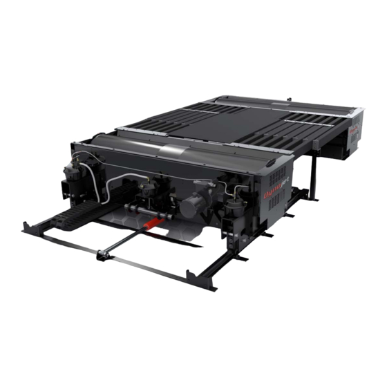
Linx Option Dyno Movement Stationary Dyno Hydraulic Motor Eddy Current Brake with eddy current brake driver Spring Applied Air Brake 4WD Dyno Track Assembly Figure 1-4: Model 424 Stationary and 4WD Dynamometer In Ground Model 424x/424xLC Automotive Dynamometer Installation Guide 1-12... -
Page 25: Model 424 4Wd Dynamometer With Pit Covers
S P E C I F I C A T I O N S A N D O P E R A T I N G R E Q U I R E M E N T S Model 424 4WD Dynamometer With Pit Covers... -
Page 26: Dynoware Rt Electronics
C H A P T E R 1 DynoWare RT Electronics DYNOWARE RT ELECTRONICS The DynoWare RT electronics consists of a main module and a speed pickup. Optional modules include the Air Fuel Ratio (AFR) module and the Eddy Current Brake (ECB) driver. -
Page 27: Main Module Connections
Connect to the drum 1 and Refer to Do not press this button unless drum 2 speed inputs and Instructions instructed to do so by a Dynojet digital brake outputs. Technician. This button may need to be pressed to update the device. -
Page 28: Network Connections
ETWORK ONNECTIONS The Dynojet DynoWare RT dyno electronics connects to your computer directly or over a Local Area Network. If you have an existing network, connect the DynoWare RT main module to a router or a network switch on your network. If you don't have an existing network, you can create a network for the DynoWare RT by connecting the main module to a router. -
Page 29: Pit Specifications
• pit length: 88-130-inch wheel base 452.12 cm (178.00 in.) 98-140-inch wheel base 477.52 cm (188.00 in.) Note: Extended wheel base requires extension parts, inquire with Dynojet sales. • pit width: with no eddy current brake 233.68 cm (92.00 in.)... - Page 31 HAPTER TATIONARY NSTALLATION This chapter will walk you through unpacking and installing the stationary dyno. To ensure safety and accuracy in the procedures, perform the procedures as they are described. This chapter is divided into the following categories: • Unpacking and Inspecting the Dyno, page 2-2 •...
-
Page 32: Unpacking And Inspecting The Dyno
UNPACKING AND INSPECTING THE DYNO When you receive your dyno, examine the exterior of the shipping container for any visible damage. If damage is detected at this stage, contact the shipper or Dynojet before proceeding. Use the following steps to unload your dyno. You will need to provide equipment capable of lifting a minimum of 2,114 kg (4,660 lb.) to move the crated dyno into... - Page 33 S T A T I O N A R Y D Y N O I N S T A L L A T I O N Unpacking and Inspecting the Dyno part description part description drum guard, right, network cable 4WD dyno...
- Page 34 P/N 21519811 P/N 76950798 *included with the optional air fuel module runner extension, right cable, CAN control adapter P/N 21519812 P/N 76950807 chock (4) bolt kit, 424 bridge P/N 2A092 P/N 79110002 In Ground Model 424x/424xLC Automotive Dynamometer Installation Guide...
- Page 35 3/8-16 x 1.5", flange, model 224x dyno hex (4) P/N 81200001 P/N 36582471 bolt, 3/8-16 x 3", flange, banner, dynojet (2) hex (5) P/N D706 P/N 36584871 washer, 3/8", flat (8) bolt, 3/8-16 x 1", hex (6) P/N 36923100...
- Page 36 C H A P T E R 2 Unpacking and Inspecting the Dyno part description part description The following parts are included in each Ground Hook Kit P/N 79100005: ground hook/D-ring washer, 5/16", flat (2) P/N 10111 P/N DM150-002-007 washer, 3/8", splitlock, ...
-
Page 37: Dyno Installation
(4,660 lb.) to lift the dyno off the crate and into position in your dyno room. You will also need a pair of straps capable of supporting the same weight. Dynojet recommends using two 2-inch x 6-foot single loop style straps. - Page 38 C H A P T E R 2 Dyno Installation Route the loop strap through the opening in the dyno frame and through itself. Pull the strap tight. Do this on each side of the dyno frame. Push the forklift forks together. Place each loop strap over both forks.
- Page 39 S T A T I O N A R Y D Y N O I N S T A L L A T I O N Dyno Installation 11 With the dyno on the forklift, secure the four riser foot assemblies to the bottom of the dyno using one 3/8-16 x 1.5-inch bolt, lock washer, and washer each.
-
Page 40: Placing The Dyno In The Pit
C H A P T E R 2 Dyno Installation LACING THE YNO IN THE Using the forklift, gently lower the dyno into the pit. Note: Make sure the dyno air brake is facing towards the center of the pit. Gently lower the dyno into position. -
Page 41: Anchoring The Dyno
Dyno Installation NCHORING THE Dynojet recommends you secure your dyno to the floor in your dyno room using concrete anchors. Use the following instructions to secure the dyno to the floor. Note: Make sure you install and align the eddy current brake with the dyno before anchoring the dyno. -
Page 42: Installing The Air Fittings
C H A P T E R 2 Dyno Installation NSTALLING THE ITTINGS Before the stationary dyno can be used with the 4WD dyno, the existing air fittings on the stationary dyno must be upgraded. You will need the following parts: •... -
Page 43: Eddy Current Brake Installation
S T A T I O N A R Y D Y N O I N S T A L L A T I O N Eddy Current Brake Installation EDDY CURRENT BRAKE INSTALLATION Refer to Chapter 4 for eddy current brake installation instructions and install your eddy current brake at this time. - Page 45 HAPTER 4WD D NSTALLATION This chapter will walk you through unpacking and installing the 4WD dyno. To ensure safety and accuracy in the procedures, perform the procedures as they are described. This chapter is divided into the following categories: • Unpacking and Inspecting the Dyno, page 3-2 •...
-
Page 46: Unpacking And Inspecting The Dyno
UNPACKING AND INSPECTING THE DYNO When you receive your dyno, examine the exterior of the shipping container for any visible damage. If damage is detected at this stage, contact the shipper or Dynojet before proceeding. Use the following steps to unload your dyno. You will need to provide equipment capable of lifting a minimum of 2,495 kg (5,500 lb.) to move the crated dyno into... - Page 47 4 W D D Y N O I N S T A L L A T I O N Unpacking and Inspecting the Dyno part description part description spacer, rail clamp (8) calibration arm assembly P/N 26152020 P/N 61319001 rail clip (10) runner assembly (30)...
- Page 48 C H A P T E R 3 Unpacking and Inspecting the Dyno Remove the crate braces that support the top portion of the crate. Remove the four lag bolts and washers securing the dyno to the crate base using a 9/16-inch socket, open or box end wrench.
-
Page 49: Track Assembly Installation
4 W D D Y N O I N S T A L L A T I O N Track Assembly Installation TRACK ASSEMBLY INSTALLATION The stationary dyno must be installed before proceeding with the 4WD dyno installation. Refer to Chapter 2 for stationary dyno installation instructions. - Page 50 153.67 cm (60.50 in.) center line for with extension stationary dyno and (requires extension track assembly parts, inquire with Dynojet sales) 184.15 cm (72.5 in.) track layout first rail tie assembly 49.37 cm (19.438 in.) first rail tie 103.82 cm (40.875 in.)
-
Page 51: Installing The Track Assembly
4 W D D Y N O I N S T A L L A T I O N Track Assembly Installation NSTALLING THE RACK SSEMBLY Once all the holes are marked and drilled, install the track assembly. You will need the following parts: •... - Page 52 C H A P T E R 3 Track Assembly Installation Loosely install the ten rail tie clips using one 3/8-16 x 1.5-inch flange-head bolt per clip. There are five rail tie clips on the outside of each track assembly. Note: The inside rail tie clips are welded to the rail tie assemblies and do not need to be secured with bolts.
-
Page 53: Dyno Installation
(5,500 lb.) to lift the dyno off the crate and into position in your dyno room. You will also need a pair of straps capable of supporting the same weight. Dynojet recommends using two 2-inch x 6-foot single loop style straps. -
Page 54: Placing The Dyno On The Track
C H A P T E R 3 Dyno Installation LACING THE YNO ON THE RACK You will need to keep the cable track routed underneath the dyno and towards the stationary dyno. You will need the following parts: • 26152020 Spacer, Rail Clamp (8) •... - Page 55 4 W D D Y N O I N S T A L L A T I O N Dyno Installation Secure the rail clamps to the cradle assembly on the dyno using two 3/8-inch shoulder bolts and two spacers each. Replace the pins and cotter pins removed earlier from the four cradle assemblies as shown in Figure 3-6.
-
Page 56: Eddy Current Brake Installation
C H A P T E R 3 Eddy Current Brake Installation EDDY CURRENT BRAKE INSTALLATION Refer to Chapter 4 for eddy current brake installation instructions and install your eddy current brake at this time. AD543 Figure 3-8: Eddy Current Brake In Ground Model 424x/424xLC Automotive Dynamometer Installation Guide 3-12... -
Page 57: Cable Routing
4 W D D Y N O I N S T A L L A T I O N Cable Routing CABLE ROUTING The DynoWare RT module and AFR module must be placed near the conduits in the pit. Be sure to keep the power and communications cables in different pit conduits. For the following instructions, we will designate the pit conduits as shown Figure 3-9. -
Page 58: Identifying The Cables
C H A P T E R 3 Cable Routing DENTIFYING THE ABLES Use the following instructions to identify and route the cables for dynos with and without eddy current brakes. • Routing the Cables—Without the Eddy Current Brakes, page 3-17 •... - Page 59 4 W D D Y N O I N S T A L L A T I O N Cable Routing cable brief routing description I - 76950201 primary RPM pick up cable connects to the DynoWare RT - 76950203 secondary pick up cable J - 76950311 power cable connects the eddy current brake driver to a power outlet...
- Page 60 C H A P T E R 3 Cable Routing cable brief routing description R - 76950807 CAN control cable, adapter, 2' connects the DynoWare RT to the CAN control and CAN dyno user cables S - 76952008 4WD power supply with cable connects the 4WD board to the 4WD power cable (B) T - 76953004 dyno movement pendant cable connects to the 4WD board...
- Page 61 4 W D D Y N O I N S T A L L A T I O N Cable Routing —W OUTING THE ABLES ITHOUT THE URRENT RAKES Use the following instructions along with Figure 3-12 on page 3-20 for routing cables without eddy current brakes.
- Page 62 C H A P T E R 3 Cable Routing Route the speed pickup/brake cable (K) from the speed pickup card and the brake solenoid leads on the stationary dyno, through the pit conduit, to DRUM 1 on the back of the DynoWare RT module. Route the speed pickup/brake cable (K) from the second cable track, through the pit conduit, to DRUM 2 on the back of the DynoWare RT module.
- Page 63 4 W D D Y N O I N S T A L L A T I O N Cable Routing 14 Attach the CAN adapter cable (R) to the back of the DynoWare RT main module. 15 Attach the CAN dyno user cable (Q) to the CAN adapter cable (R) and route to the AFR assembly.
- Page 64 C H A P T E R 3 Cable Routing Figure 3-12: Routing the Cables—Without the Eddy Current Brakes In Ground Model 424x/424xLC Automotive Dynamometer Installation Guide 3-20...
- Page 65 4 W D D Y N O I N S T A L L A T I O N Cable Routing —W OUTING THE ABLES URRENT RAKE Use the following instructions along with Figure 3-15 on page 3-24 for routing cables with one eddy current brake.
- Page 66 C H A P T E R 3 Cable Routing 10 Route the rail brake air hose (W) from the second cable track to the T fitting on the air brake can on the stationary dyno. The air brake comes installed with a hose barb for a 3/8-inch inside diameter air hose.
- Page 67 4 W D D Y N O I N S T A L L A T I O N Cable Routing 18 Attach the CAN adapter cable (R) to the back of the DynoWare RT main module. 19 Attach the CAN dyno user cable (Q) to the CAN adapter cable (R) and route to the AFR assembly.
- Page 68 C H A P T E R 3 Cable Routing Figure 3-15: Routing the Cables—With One Eddy Current Brake In Ground Model 424x/424xLC Automotive Dynamometer Installation Guide 3-24...
- Page 69 4 W D D Y N O I N S T A L L A T I O N Cable Routing —W OUTING THE ABLES URRENT RAKES Use the following instructions along with Figure 3-18 on page 3-28 for routing cables with two eddy current brakes.
- Page 70 C H A P T E R 3 Cable Routing Attach the CAN adapter cable (R) to the back of the DynoWare RT main module. 10 Attach the CAN dyno user cable (Q) to the CAN adapter cable (R) and route to the AFR assembly.
- Page 71 4 W D D Y N O I N S T A L L A T I O N Cable Routing 17 Route the hydraulic pump power cable (H) from the first cable track, through the pit conduit, and connect to a 110VAC or 220VAC outlet. The pump motor is wired for 110VAC, refer to Figure 3-25 on page 3-35 for more information on wiring the hydraulic pump motor.
- Page 72 C H A P T E R 3 Cable Routing Figure 3-18: Routing Cables—With Two Eddy Current Brakes In Ground Model 424x/424xLC Automotive Dynamometer Installation Guide 3-28...
-
Page 73: Aligning The Speed Pickup Card
4 W D D Y N O I N S T A L L A T I O N Cable Routing LIGNING THE PEED ICKUP The speed pickup card is an electronic circuit board that accurately senses each drum revolution and is recessed into the side of your dyno. The speed pickup card comes installed with the cable secured, but should be checked for alignment before the drum is turned. -
Page 74: Hydraulic Movement Installation
HYDRAULIC MOVEMENT INSTALLATION Use the following instructions to install the hydraulic movement. You will need the following parts: • 26100000 Spacer,424 Hydraulic Movement (2) • 32900000 Clevis Pin, 3/4 x 4.5" (2) • 32904080 Hairpin Cotter, 7/16 x 3/4" (2) •... - Page 75 4 W D D Y N O I N S T A L L A T I O N Hydraulic Movement Installation Secure the hydraulic ram to the dyno cylinder mount using one clevis pin and hairpin cotter. AD343 dyno cylinder mount hydraulic ram clevis pin hairpin cotter...
- Page 76 C H A P T E R 3 Hydraulic Movement Installation Temporarily hold the floor cylinder mount to the hydraulic ram using two spacers and one clevis pin. spacers A 556 clevis pin floor cylinder mount hydraulic ram Figure 3-22: Hold the Floor Cylinder Mount to the Ram In Ground Model 424x/424xLC Automotive Dynamometer Installation Guide 3-32...
- Page 77 4 W D D Y N O I N S T A L L A T I O N Hydraulic Movement Installation Using the floor cylinder mount as a template, mark each hole needed to secure the mount to the floor. Remove the clevis pin, spacers, and floor cylinder mount.
-
Page 78: Filling The Hydraulic Motor With Hydraulic Fluid
C H A P T E R 3 Hydraulic Movement Installation ILLING THE YDRAULIC OTOR WITH YDRAULIC LUID Remove the cap on the hydraulic motor. Add four quarts of AW-68 hydraulic fluid. Replace the cap. remove the cap on the hydraulic motor Figure 3-24: Fill the Hydraulic Motor with Oil In Ground Model 424x/424xLC... -
Page 79: Wiring The Hydraulic Motor
4 W D D Y N O I N S T A L L A T I O N Hydraulic Movement Installation IRING THE YDRAULIC OTOR Verify the motor is wired for your needs. The motor is wired for 110V but can be changed to 220V. - Page 80 C H A P T E R 3 Hydraulic Movement Installation Figure 3-26: Hydraulic Movement Wiring Diagram In Ground Model 424x/424xLC Automotive Dynamometer Installation Guide 3-36...
-
Page 81: Air Can Sleeve
4 W D D Y N O I N S T A L L A T I O N Air Can Sleeve AIR CAN SLEEVE When you receive your dyno, the nut holding the air can sleeve will be tight. You will need to loosen the nut on all four air cans. -
Page 82: 4Wd Dyno Movement Test
C H A P T E R 3 4WD Dyno Movement Test 4WD DYNO MOVEMENT TEST Verify the movement of the 4WD dyno before installing the covers. Verify the hydraulic motor is filled with hydraulic fluid. Refer to “Filling the Hydraulic Motor with Hydraulic Fluid”... -
Page 83: Bridge Installation-Stationary Dyno
4 W D D Y N O I N S T A L L A T I O N Bridge Installation—Stationary Dyno BRIDGE INSTALLATION—STATIONARY DYNO Use the following instructions to install the drum guards, runner mounts and supports, runner assemblies, and the bridge cover. You will need the following parts: •... -
Page 84: Installing The Drum Guards
C H A P T E R 3 Bridge Installation—Stationary Dyno NSTALLING THE UARDS Secure the longer left and right drum guards using one 3/8-16 x 1.25-inch button- head bolt each. Note: These drum guards are longer (88.90 cm, 35.00 in.) than the left and right drum guards for the 4WD dyno and must be mounted on the stationary dyno. -
Page 85: Installing The Runner Mounts And Runner Supports
4 W D D Y N O I N S T A L L A T I O N Bridge Installation—Stationary Dyno NSTALLING THE UNNER OUNTS AND UNNER UPPORTS Refer to Appendix D for bridge extension kit installation instructions. Place the runner mount (z-shaped) with eight round holes on top of the drum guard. -
Page 86: Installing The Runner Assemblies And Runner Extension
C H A P T E R 3 Bridge Installation—Stationary Dyno NSTALLING THE UNNER SSEMBLIES AND UNNER XTENSION Place the plastic runner slide on top of the runner support. Slide each runner assembly into the runner mount. Verify the plastic end faces away from the stationary dyno. - Page 87 4 W D D Y N O I N S T A L L A T I O N Bridge Installation—Stationary Dyno Install the runner extension. There is a left and right version of the runner extension; the left version is shown in Figure 3-31. Note: Do not install the runner extension on the side of the dyno where the eddy current brake or Linx will be installed.
- Page 88 Tighten the bolts securing the runner assemblies to the runner mounts. Tighten the bolts securing the runner mounts to the dyno. Dynojet recommends you anchor the support pillars to the dyno room floor, however this step is optional. Using the support pillars as a template, mark and drill each hole needed to secure the four pillars to the floor.
-
Page 89: Installing The Bridge Cover
4 W D D Y N O I N S T A L L A T I O N Bridge Installation—Stationary Dyno NSTALLING THE RIDGE OVER Remove the center bolt from the front drum guard. Place the cover on the drum guard while supporting the other end of the cover. Replace the center bolt. -
Page 90: Bridge Installation-4Wd Dyno
C H A P T E R 3 Bridge Installation—4WD Dyno BRIDGE INSTALLATION—4WD DYNO This section will walk you through installing the drum guards, runner mounts, runner assemblies, cover, and runner tie straps. You will need the following parts: • 21214701 Runner Tie Strap (2) •... - Page 91 4 W D D Y N O I N S T A L L A T I O N Bridge Installation—4WD Dyno NSTALLING THE UARDS Secure the shorter left and right drum guards using one 3/8 x 1.25-inch button- head bolt each. Note: These drum guards are shorter than the left and right drum guards for the stationary dyno and must be mounted on the 4WD dyno.
-
Page 92: Installing The Runner Mounts
C H A P T E R 3 Bridge Installation—4WD Dyno NSTALLING THE UNNER OUNTS The runner mounts and runner clamps are shorter for the moveable dyno. Place the runner mount (z-shaped) with seven round holes on top of the drum guard. -
Page 93: Installing The Runner Assemblies
4 W D D Y N O I N S T A L L A T I O N Bridge Installation—4WD Dyno NSTALLING THE UNNER SSEMBLIES Slide each runner assembly into the runner mount. Verify the plastic end faces away from the 4WD dyno. Loosely secure the six outside runner assemblies to the runner mount using one 3/8 x 5-inch bolt, flat washer, lock washer, and nut each. -
Page 94: Installing The Bridge Cover And Runner Tie Straps
C H A P T E R 3 Bridge Installation—4WD Dyno NSTALLING THE RIDGE OVER AND UNNER TRAPS Secure the cover to the runner mounts using the two reserved 3/8 x 1.5-inch flange hex allen bolts from earlier. Secure the cover to the runner assemblies using two 1/4 x 5/8-inch torx head bolts. -
Page 95: Linx Installation
4 W D D Y N O I N S T A L L A T I O N Linx Installation LINX INSTALLATION Refer to Chapter 5 for Linx installation instructions and install your Linx at this time. The Linx belt drive system is an optional accessory. If you did not order the Linx system, continue with “Forward Pit Covers”... -
Page 96: Forward Pit Covers
C H A P T E R 3 Forward Pit Covers FORWARD PIT COVERS Use the following instructions to install the 4WD dyno pit covers. You will need the following parts: • 21219116 Forward Pit Cover, Right • 21219117 Forward Pit Cover, Middle •... - Page 97 4 W D D Y N O I N S T A L L A T I O N Forward Pit Covers Secure the left and right pit covers to the pit cover spacer and dyno frame using two 3/8-16 x 3-inch bolts each. Secure the left and right pit covers to the middle pit cover using five ...
-
Page 98: Ground Hook Installation
C H A P T E R 3 Ground Hook Installation GROUND HOOK INSTALLATION Using the pit drawing as a guide, place the ground hooks in a location that works best for your dyno application. Refer to the pit specifications (P/N 98219114 for standard wheel base and P/N 98219113 for extended wheel base) you received from your salesman for more detailed specifications. -
Page 99: Eddy Current Brake Installation
URRENT RAKE NSTALLATION The eddy current brake along with the load cell assembly, when added to Dynojet's market leading inertia dynamometer, results in a complete vehicle performance test. This chapter provides instructions for installing the eddy current brake (retarder) to the stationary and 4WD dynos. -
Page 100: Before Installing The Eddy Current Brake: Verify Optimal Brake Cooling
4WD dynos. You will need to provide equipment capable of lifting the eddy current brake off the crate and into position in your dyno room. You will also need a pair of straps. Dynojet recommends using single loop style straps. - Page 101 E D D Y C U R R E N T B R A K E I N S T A L L A T I O N Eddy Current Brake Installation EFORE NSTALLING THE URRENT RAKE ERIFY THE OUNTING OLES Dynos with the serial number 2240308 and lower will need to have mounting holes drilled into the dyno frame before installing the eddy current brake.
-
Page 102: Unpacking The Eddy Current Brake
C H A P T E R 4 Eddy Current Brake Installation NPACKING THE URRENT RAKE Remove the top and sides of the crate. Remove any hardware and parts boxes from the crate and verify the box contents. part description part description screw, 4-40 x 1/4", ... - Page 103 E D D Y C U R R E N T B R A K E I N S T A L L A T I O N Eddy Current Brake Installation part description part description nut, 8-32, with lock washer, 3/8", flat (10)...
- Page 104 C H A P T E R 4 Eddy Current Brake Installation Remove the uprights and cross members from the crate. crate top uprights and cross members remove boxes Figure 4-3: Remove the Crate Top In Ground Model 424x/424xLC Automotive Dynamometer Installation Guide...
- Page 105 Remove the four lag bolts securing the brake to the crate. Place the nylon loop strap around the shaft on either side of the brake. Dynojet recommends using single loop style straps. Using a forklift, lift the eddy current brake from the crate and place the brake near the dyno.
-
Page 106: Installing The Temperature Sensor
C H A P T E R 4 Eddy Current Brake Installation NSTALLING THE EMPERATURE ENSOR Use the following instructions to secure the temperature sensor to the eddy current brake in the location shown. You will need the following part: •... -
Page 107: Installing The Bearing, Spline Shaft, And Driveline Assembly
E D D Y C U R R E N T B R A K E I N S T A L L A T I O N Eddy Current Brake Installation NSTALLING THE EARING PLINE HAFT RIVELINE SSEMBLY The eddy current brake can be installed on either side of your dyno, the installation instructions are the same. - Page 108 C H A P T E R 4 Eddy Current Brake Installation Insert the splined shaft through the bearing and into the spline hub of the drum. Note: Make sure the short splined end faces out. Push the splined shaft in until it bottoms out then back the shaft out 1/4-inch. Note: Make sure to back the shaft out 1/4-inch to prevent friction.
- Page 109 E D D Y C U R R E N T B R A K E I N S T A L L A T I O N Eddy Current Brake Installation NSTALLING THE URRENT RAKE You will need the following parts: •...
- Page 110 C H A P T E R 4 Eddy Current Brake Installation Secure the side of the brake frame to the dyno using eight 3/8-16 x 1-inch hex bolts and eight 3/8-inch hardened flat washers. Not all of the bolts and washers are visible from this view.
-
Page 111: Installing The Load Cell
E D D Y C U R R E N T B R A K E I N S T A L L A T I O N Eddy Current Brake Installation NSTALLING THE You will need the following part: •... - Page 112 C H A P T E R 4 Eddy Current Brake Installation NSTALLING THE URRENT RAKE RIVER Use the following instructions to install the eddy current brake driver to both the stationary and 4WD dynos. You will need the following parts: •...
- Page 113 E D D Y C U R R E N T B R A K E I N S T A L L A T I O N Eddy Current Brake Installation Secure the mounting bracket to the eddy current brake using two 3/8-16 x 1-inch bolts, two 3/8-inch flat washers, and two 3/8-inch nylock nuts.
-
Page 114: Pit Covers Installation
C H A P T E R 4 Pit Covers Installation PIT COVERS INSTALLATION Before installing the eddy current brake pit covers, verify all cables have been routed and you have completed the 4WD dyno installation. Refer to “Cable Routing” on page 3-13 for more information. - Page 115 E D D Y C U R R E N T B R A K E I N S T A L L A T I O N Pit Covers Installation Using the support leg as a template, mark and drill the two holes needed to secure the leg to the floor.
- Page 116 C H A P T E R 4 Pit Covers Installation 13 Once you have calibrated the load cell, install the pit calibration covers using six 1/4-20 x 5/8-inch torx screws each. Note: Do not install these covers until you have finished calibrating the load cell. Refer to “Load Cell Calibration”...
-
Page 117: Load Cell Calibration
E D D Y C U R R E N T B R A K E I N S T A L L A T I O N Load Cell Calibration LOAD CELL CALIBRATION This section provides instructions for calibrating the load cell(s). Follow the directions on the screen exactly. - Page 118 Note: Dynojet recommends you secure the calibration arm using the bolt pattern closest to the end of the arm unless space constraints in your dyno room do not allow you to.
- Page 119 E D D Y C U R R E N T B R A K E I N S T A L L A T I O N Load Cell Calibration Place the weights towards the rear of the vehicle. Note: Calibration arm placement determines positive direction for torque.
- Page 120 C H A P T E R 4 Load Cell Calibration Install the calibration arm and weights using the bolts at the end of the calibration arm. Note: If you do not have enough room to use the bolt pattern closest to the end of the calibration arm, use the bolt pattern in the center of the arm.
- Page 121 E D D Y C U R R E N T B R A K E I N S T A L L A T I O N Load Cell Calibration 10 With the calibration arm and weights secured, click Next to continue. 11 Once sending the torque cell calibration is complete, click Next to continue.
-
Page 123: Linx Installation
This chapter provides instructions for installing the Linx system on your model 424 automotive dyno. To ensure safety and accuracy in the procedures, perform the procedures as they are described. -
Page 124: Linx Belt Drive Specifications
C H A P T E R 5 Linx Belt Drive Specifications LINX BELT DRIVE SPECIFICATIONS The following specifications specific to the Linx belt drive dyno application will help you set up your dyno area and verify you have met the requirements necessary to operate your dyno safely. -
Page 125: Unpacking The Linx Parts
L I N X I N S T A L L A T I O N Unpacking the Linx Parts UNPACKING THE LINX PARTS Use the following steps to unpack your Linx system parts. Using a pry bar and a hammer, carefully remove the top and sides of the crate. Inspect the exterior of the Linx for any indications of damage. - Page 126 C H A P T E R 5 Unpacking the Linx Parts part description part description screw, 1/4-20 x 1.75", lower moveable pulley cap, drilled (4) mount P/N 36500016 P/N 61300026 stamped 4 screw, 1/4-20 x 1.25", inner moveable dyno cap, drilled (4)...
- Page 127 L I N X I N S T A L L A T I O N Unpacking the Linx Parts part description part description washer, 9/16", flat (24) nut, 3/8-16, hex (2) P/N 36943101 P/N DM150-011-004 anchor, Red Head, 3/8" (6) bolt, 3/8-16 x 1.25", hex (4)...
- Page 128 C H A P T E R 5 Unpacking the Linx Parts part description part description The following parts are included in the Linx Belt Covers P/N 78100011: washer, 3/8", hardened, pit cover mount P/N 21200098 flat (6) P/N 36923100 calibration access cover (2)...
-
Page 129: Inner Mounting Plate Installation
L I N X I N S T A L L A T I O N Inner Mounting Plate Installation INNER MOUNTING PLATE INSTALLATION Use the following instructions to install the moveable dyno and stationary dyno inner mounting plates. You will need the following parts: •... -
Page 130: Inner Mounting Plate Installation
C H A P T E R 5 Inner Mounting Plate Installation Using the access holes, secure the bottom of the inner mounting plate to the moveable dyno using two 3/8-16 x 1.5-inch flange bolts, two 3/8-inch flat washers, and two 3/8-inch nuts. access hole Figure 5-3: Secure the Bottom of the Inner Mounting Plate to the Moveable Dyno —S... -
Page 131: Flange Bearing, Outer Shaft, And Splined Shaft Installation
L I N X I N S T A L L A T I O N Flange Bearing, Outer Shaft, and Splined Shaft Installation FLANGE BEARING, OUTER SHAFT, AND SPLINED SHAFT INSTALLATION Use the following instructions to install the flange bearing, splined shaft, and outer shaft on both the moveable and stationary dynos. -
Page 132: Flange Bearing, Outer Shaft, And Splined Shaft Installation
C H A P T E R 5 Flange Bearing, Outer Shaft, and Splined Shaft Installation Apply a small amount of grease to the first two inches of the splined shaft. Slide the splined shaft through the outer shaft and into the splines in the dyno drum. -
Page 133: Drive Pulley Installation
L I N X I N S T A L L A T I O N Drive Pulley Installation DRIVE PULLEY INSTALLATION Use the following instructions to install the drive pulleys for both the moveable and stationary dynos. You will need the following parts: •... - Page 134 C H A P T E R 5 Drive Pulley Installation The outer face of the pulley should be approximately 27.5 cm (10-13/16 in.) from the face of the inner plate. Slowly tighten the bolts until the hub starts to pull into the pulley, checking that it is approximately 27.5 cm (10-13/16 in.) from the inner plate before the pulley is locked on the shaft.
-
Page 135: Idler Pulley Assembly Installation
L I N X I N S T A L L A T I O N Idler Pulley Assembly Installation IDLER PULLEY ASSEMBLY INSTALLATION You will need the following parts: • 32300001 Flange Bearing with Lock Collar • 36711100 Nut, 9/16-12, Hex (4) •... -
Page 136: Belt And Tensioner Pulley Assembly Installation
C H A P T E R 5 Belt and Tensioner Pulley Assembly Installation BELT AND TENSIONER PULLEY ASSEMBLY INSTALLATION You will need the following parts: • 36923100 Washer, 3/8", Flat (8) • 37513200 Anchor, Red Head, 3/8" (8) • 37518200 Red Head Anchor Installation Tool •... - Page 137 L I N X I N S T A L L A T I O N Belt and Tensioner Pulley Assembly Installation tensioner pulley towards stationary dyno apply grease to ACME threads welded nuts towards back Figure 5-11: Install the Belt and Tensioner Pulley Assembly Version 6 In Ground Model 424x/424xLC Automotive Dynamometer Installation Guide...
-
Page 138: Pulley Mounting Plates And Outer Bearings Installation
C H A P T E R 5 Pulley Mounting Plates and Outer Bearings Installation PULLEY MOUNTING PLATES AND OUTER BEARINGS INSTALLATION The inner pulley mounting plates and the pulley mounts are stamped with numbers to help match the parts and guide you in the installation process. You will need the following parts: •... - Page 139 L I N X I N S T A L L A T I O N Pulley Mounting Plates and Outer Bearings Installation NSTALLING THE DLER ULLEY UTER EARING EARING OUNTING LATE ETECT ENSOR OWER ULLEY OUNT Secure the Linx detect sensor to the mounting plate using two #8-32 screws. Loosely secure the Linx detect sensor and mounting plate assembly to the mounting bracket using two #8-32 screws.
- Page 140 C H A P T E R 5 Pulley Mounting Plates and Outer Bearings Installation Secure the Linx detect sensor tab to the pickup collar using one #8-32 screw. Note: Verify the tab is positioned perpendicular to the pickup collar as shown in Figure 5-14.
- Page 141 L I N X I N S T A L L A T I O N Pulley Mounting Plates and Outer Bearings Installation Place a lower stationary dyno pulley mount (P/N 61300023, stamped 2) under the idler pulley and loosely secure the mount to the inner plate using five 3/8-16 x 1-inch bolts and five 3/8-inch flat washers (one of the holes in the pulley mount is not used).
- Page 142 C H A P T E R 5 Pulley Mounting Plates and Outer Bearings Installation NSTALLING THE OVEABLE ULLEY UTER EARING EARING OUNTING LATE OWER ULLEY OUNT Secure the outer moveable dyno pulley bearing to the moveable dyno pulley bearing plate using four 9/16-12 x 2-inch bolts, four 9/16-inch flat washers, and four 9/16-inch nuts.
- Page 143 L I N X I N S T A L L A T I O N Pulley Mounting Plates and Outer Bearings Installation NSTALLING THE PPER OVEABLE ULLEY AND DLER ULLEY OUNTS Place a lower stationary dyno pulley mount (P/N 61300023, stamped 2) over the moveable dyno pulley and loosely secure the mount to the inner plate using ...
- Page 144 C H A P T E R 5 Pulley Mounting Plates and Outer Bearings Installation Place the upper moveable dyno pulley mount (P/N 61300025, stamped 3) over the idler pulley and loosely secure the mount to the inner plate using five 3/8-16 x 1-inch bolts and five 3/8-inch flat washers.
- Page 145 L I N X I N S T A L L A T I O N Pulley Mounting Plates and Outer Bearings Installation Remove the 1/4-20 x 1.75-inch cap screws from the splined shaft. Verify the splined shaft will slide in and out of the dyno splines easily once all the bolts are tightened.
- Page 146 C H A P T E R 5 Pulley Mounting Plates and Outer Bearings Installation NSTALLING THE TATIONARY ULLEY UTER EARING EARING OUNTING LATE OWER ULLEY OUNT Secure the outer stationary dyno pulley bearing to the stationary dyno pulley bearing plate using four 9/16-12 x 2-inch bolts, four 9/16-inch flat washers, and four 9-16-inch nuts.
- Page 147 L I N X I N S T A L L A T I O N Pulley Mounting Plates and Outer Bearings Installation NSTALLING THE PPER TATIONARY ULLEY OUNT Place the upper stationary dyno pulley mount (P/N 61300022, stamped 1) over the stationary dyno pulley and loosely secure the mount to the inner plate using ...
- Page 148 C H A P T E R 5 Pulley Mounting Plates and Outer Bearings Installation Remove the 1/4-20 x 1.75-inch cap screws from the splined shaft. Verify the splined shaft will slide in and out of the dyno splines easily once all the bolts are tightened.
-
Page 149: Linx Detect Sensor Cable Routing
L I N X I N S T A L L A T I O N Linx Detect Sensor Cable Routing LINX DETECT SENSOR CABLE ROUTING Use the following instructions to route the Linx detect sensor cable to the DynoWare RT module. - Page 150 C H A P T E R 5 Linx Detect Sensor Cable Routing Remove the two screws and washers securing the cable track containing the signal cables to the front rail tie assembly. Pull the cable track out from under the dyno. Note: Do not place the Linx detect sensor cable in the track with the power cables.
-
Page 151: Brake Signal Relay Installation
L I N X I N S T A L L A T I O N Brake Signal Relay Installation BRAKE SIGNAL RELAY INSTALLATION Use the following instructions along with Figure 5-28 on page 5-30 only if you are upgrading an existing dyno. If you are installing a new dyno, skip these instructions and continue with “Tension the Belt”... - Page 152 C H A P T E R 5 Brake Signal Relay Installation secure relay to 4WD board using existing nut Figure 5-28: Install the Brake Signal Relay to the 4WD Board In Ground Model 424x/424xLC Automotive Dynamometer Installation Guide 5-30...
-
Page 153: Tension The Belt
L I N X I N S T A L L A T I O N Tension the Belt TENSION THE BELT The Linx belt drive system is designed for all-wheel drive vehicles. The Linx belt drive system keeps the driving wheels of an all-wheel drive vehicle spinning at the same speed to avoid driveline damage. - Page 154 C H A P T E R 5 Tension the Belt mark 50.50 in. from center of drum angle on underside of bridge tube weights tension arm lock nuts ACME screws Figure 5-29: Tension the Belt In Ground Model 424x/424xLC Automotive Dynamometer Installation Guide 5-32...
-
Page 155: Linx Belt Covers Installation
L I N X I N S T A L L A T I O N Linx Belt Covers Installation LINX BELT COVERS INSTALLATION You will need the following parts: • 21200098 Pit Cover Mount • 21217513 Calibration Access Cover (2) •... - Page 156 C H A P T E R 5 Linx Belt Covers Installation Remove the 1/4-20 x 5/8-inch torx screw from the outer most tube of the dyno bridge. Secure the center support assembly to the outer bridge tube using the screw removed earlier.
- Page 157 L I N X I N S T A L L A T I O N Linx Belt Covers Installation Place the pit cover assemblies on the floor in the position shown. Secure the covers to the center support using two 3/8-16 x 1/2-inch button-head flange bolts.
-
Page 158: Continue Dyno Installation
C H A P T E R 5 Linx Belt Covers Installation Secure the six angle feet to the pit cover assemblies in the positions shown using one 3/8-16 x 1/2-inch button-head flange bolt each. Using the feet as a template, drill each hole needed to secure the feet to the floor. Install the six Red Head anchors. -
Page 159: Disconnect The Belt Drive From The Dyno Drums
L I N X I N S T A L L A T I O N Disconnect the Belt Drive from the Dyno Drums DISCONNECT THE BELT DRIVE FROM THE DYNO DRUMS The Linx belt can be disengaged by pulling the splined shafts out of the dyno splines. Remove the six 1/4-20 x 5/8-inch torx screws securing each access cover and set aside. -
Page 160: Reconnecting The Belt Drive
C H A P T E R 5 Disconnect the Belt Drive from the Dyno Drums ECONNECTING THE RIVE Remove the 1/4-20 x 1.25-inch cap screws from the threaded holes in the splined shaft. Slide the shaft into the dyno drum aligning the two unthreaded holes in the splined shaft flange with the two threaded holes in the outer shaft. -
Page 161: Basic Dyno Operation
HAPTER ASIC PERATION The Dynojet dynamometer gives you the state of the art technology, durability, and accuracy that you need. Dynojet’s advanced engineering delivers the precise horsepower measurements a technician needs to make quick and accurate evaluations of engine performance and drivetrain problems. -
Page 162: Loading The Vehicle
C H A P T E R 6 Loading the Vehicle LOADING THE VEHICLE Use the following steps to load a vehicle on the dyno. You will need the following parts: part description part description tire chock (4) car tie-down, 2" x 10' (4) P/N 2A092 P/N 500-C10 short axle strap, 10M #, ... - Page 163 B A S I C D Y N O O P E R A T I O N Loading the Vehicle Verify your computer is running. Set the dyno brake by pressing the red button on the hand-held pendant. Measure the wheel base on four or all-wheel drive vehicles and adjust the 4WD dyno to that dimension before driving the vehicle on the dyno.
- Page 164 C H A P T E R 6 Loading the Vehicle Attach the tie-down straps. Rear Wheel Drive • Attach two tie-down straps from secure anchor points to the rear of the vehicle. Attach additional tie-down straps from the rear of the vehicle as shown in Figure 6-2.
- Page 165 B A S I C D Y N O O P E R A T I O N Loading the Vehicle Tighten the tie-down straps evenly making sure the drive wheels remain centered on the drum. The tie-down straps should always be connected to the vehicle’s solid axle or the suspension control arms.
-
Page 166: Connecting The Rpm Pickup
Connecting the RPM Pickup CONNECTING THE RPM PICKUP Your Dynojet dynamometer includes two primary wire inductive pickups and two secondary wire inductive pickups. These small “clothespin like” inductive pickups are used to sense RPM. An RPM pickup is required if you want to view torque graphs. -
Page 167: Connecting The Secondary Inductive Pickup
B A S I C D Y N O O P E R A T I O N Connecting the RPM Pickup ONNECTING THE ECONDARY NDUCTIVE ICKUP The secondary inductive pickup cannot be in contact with, or its connecting wire be crossing other engine electrical wires or stray electrical interference may result. -
Page 168: Connecting The Primary Inductive Pickup
C H A P T E R 6 Connecting the RPM Pickup ONNECTING THE RIMARY NDUCTIVE ICKUP The primary inductive pickup cannot be in contact with, or its connecting wire be crossing other engine electrical wires or stray electrical interference may result. Clip the primary inductive pickup around the negative side of the coil. -
Page 169: Grounding The Vehicle
B A S I C D Y N O O P E R A T I O N Grounding the Vehicle GROUNDING THE VEHICLE You will need to ground your vehicle to the dyno before every run. Use the following steps to install the grounding bracket and ground the vehicle to the dyno. -
Page 170: Pre-Run Inspection
C H A P T E R 6 Pre-Run Inspection PRE-RUN INSPECTION Perform a vehicle inspection before making a run. • Check the radiator coolant and oil levels. • Check the fuel source. • Rotate the drum(s) and check for rocks caught in the tire tread that could fly out. •... -
Page 171: Engine Warm Up
B A S I C D Y N O O P E R A T I O N Pre-Run Inspection NGINE Warm the vehicle’s engine and drivetrain before beginning testing. Consistent engine temperatures will assure your runs are repeatable. FTER NGINE Always leave the vehicle in park (automatic transmission) or in first gear (manual transmission), with the engine off, and make sure the emergency brake and the dyno... -
Page 172: Making A Test Run
Press the red brake button to apply 100% braking and slow down the vehicle. Using the vehicle’s own brakes to slow or stop the drum at speeds over 30 m.p.h. can severely overheat the brake parts. Dynojet dynamometers with the air brake or eddy current brake accessory can be used to slow the vehicle and drum to a full stop at any speed. -
Page 173: Preventative Maintenance
B A S I C D Y N O O P E R A T I O N Preventative Maintenance PREVENTATIVE MAINTENANCE This section covers maintenance items for all model 424 dynos with the Spring Applied Air Release (SAAR) brake and the 4WD attachment. For more detailed maintenance instructions, refer to the Maintenance Guide for Automotive... - Page 174 C H A P T E R 6 Preventative Maintenance SAAR B ERIFYING THE RAKE RESSURE Verify the SAAR brake pressure gauge reads 100psi (690kPa). Using the knob, adjust the regulator until the correct pressure is achieved. brake pressure regulator AB096 use the knob to adjust the regulator until the correct...
- Page 175 B A S I C D Y N O O P E R A T I O N Preventative Maintenance SAAR B AINTAINING THE RAKE LEARANCE Verify the area is clear and the dyno can be operated safely. Turn on the DynoWare RT. Using the pendant, turn the brake to the OFF position.
- Page 176 Tighten the upper nut on the air can rod down onto the brake actuating tube. Torque the lower nut to 110 foot-pounds. If you cannot adjust the brakes to specification, you will need new brake shoes. Contact Dynojet for more information. air can rod upper nut...
- Page 177 B A S I C D Y N O O P E R A T I O N Preventative Maintenance 4WD A —T YNOS WITH TTACHMENT HINGS TO HECK • Check the hydraulic motor fluid once every six months, fill as necessary. •...
-
Page 179: Appendix A Red Head Anchor Installation
PPENDIX NCHOR NSTALLATION This appendix contains instructions for installing the Red Head Multi-Set™II Anchors. The anchors will be used to secure the dyno to concrete. To ensure safety and accuracy in the procedures, perform the procedures as they are described. Be sure to read and understand the warnings included in this appendix. - Page 180 A P P E N D I X A Installation INSTALLATION Use the table below to determine the catalog number, drill bit size, minimum hole depth, and setting tool catalog number. minimum hole setting tool catalog number drill bit size depth catalog number Carbon Steel...
- Page 181 R E D H E A D A N C H O R I N S T A L L A T I O N Installation Using a hammer, drive the anchor flush with the surface of the concrete, or below the surface if the hole depth exceeds minimum embedment.
-
Page 183: Appendix B Power Requirements And Installation
PPENDIX OWER EQUIREMENTS AND NSTALLATION This appendix contains power requirements and installation instructions for the eddy current brake. To ensure safety and accuracy in the procedures, perform the procedures as they are described. Be sure to read and understand the warnings included in this appendix. -
Page 184: North America, Japan, And Locations Using 60 Hz Power
UL and NEC safety standards. Note: If you are installing your brake in North American or Japan and the brake is not equipped with twist lock four wire grounded plug, contact Dynojet before attempting to connect the brake. -
Page 185: Testing For Correct Voltages
You must have a licensed electrician correct the power connection. Connecting the brake to the incorrect voltage can result in damage to the brake and will void the brake warranty. Contact Dynojet with any questions. Using a voltmeter that is capable of measuring AC voltage, measure between the points listed below and verify that the correct voltages are present. -
Page 186: Hard Wiring To The Building
A P P E N D I X B North America, Japan, and Locations Using 60 Hz Power IRING TO THE UILDING Use the following instructions to wire the brake directly to the building. The brake must connect to a two pole disconnect switch to allow the removal of all power to the brake for servicing. - Page 187 Failure to follow these instructions could result in personal injury or damage to the brake. Connecting the brake to the incorrect voltage will void the brake warranty. Contact Dynojet with any questions. The dedicated wall receptacle is a three-pin IEC grounded 30A type and must be wired in accordance with local building codes and requirements.
-
Page 188: Installing The Wall Receptacle
A P P E N D I X B Excluding North America and Japan NSTALLING THE ECEPTACLE The wall receptacle is a single 240 volt 30A dedicated circuit with a ground. Note: The actual wall receptacle may be different from the image shown in Figure B-2;... -
Page 189: Testing For Correct Voltages
P O W E R R E Q U I R E M E N T S A N D I N S T A L L A T I O N Excluding North America and Japan ESTING FOR ORRECT OLTAGES You must test the receptacle for proper voltages before the eddy current brake is connected to the outlet. - Page 191 PPENDIX TATIONARY PGRADE This appendix contains instructions for upgrading an existing stationary dyno to be used with the 4WD dyno including relocating the deck, adding the lift kit, and adjusting the air fittings. To ensure safety and accuracy in the procedures, perform the procedures as they are described.
-
Page 192: Lift Kit Installation
A P P E N D I X C Lift Kit Installation LIFT KIT INSTALLATION Once the rear deck has been removed, the lift kit must be installed. The lift kit will raise the stationary dyno to match the 4WD dyno. You will need the following parts: •... -
Page 193: Air Fittings Upgrade
S T A T I O N A R Y D Y N O U P G R A D E Air Fittings Upgrade AIR FITTINGS UPGRADE Before the stationary dyno can be used with the 4WD dyno, the existing air fittings on the stationary dyno must be upgraded. -
Page 195: Appendix D Bridge Extension Assembly
PPENDIX RIDGE XTENSION SSEMBLY This appendix contains instructions for installing the bridge extension assembly to the stationary dyno. To ensure safety and accuracy in the procedures, perform the procedures as they are described. In Ground Model 424x/424xLC Automotive Dynamometer Installation Guide... -
Page 196: Bridge Extension Installation
A P P E N D I X D Bridge Extension Installation BRIDGE EXTENSION INSTALLATION The optional bridge extension assembly (P/N 61119183) is used to extend the bridge range from an 88-130 inch vehicle wheel base to a 98-140 inch vehicle wheel base. You will need the following parts: part description... - Page 197 B R I D G E E X T E N S I O N A S S E M B L Y Bridge Extension Installation Secure the extended runner mount (z-shaped bracket) to the drum guard using three 3/8 x 1.5-inch flange hex allen bolts. Note: The extended runner mounts used with the bridge extension are longer than the standard runner mounts.
- Page 198 A P P E N D I X D Bridge Extension Installation When there is no eddy current brake, secure both outer brace mounts to the dyno using two 3/8 x 1.5-inch flange head bolts each. extended runner mount A 562 outer brace mount outer brace...
- Page 199 B R I D G E E X T E N S I O N A S S E M B L Y Bridge Extension Installation Place the runner clamp on top of the extended runner mount. Note: The extended runner clamps used with the bridge extension are smaller and rectangular shaped compared to the standard runner clamps.
- Page 200 A P P E N D I X D Bridge Extension Installation Secure the two support arms to the brackets using two 1/2 x 1.5-inch bolts, two 1/2-inch lock washers, and two 1/2-inch nuts each. brackets A 564 support arm bracket support arm bracket...
- Page 201 B R I D G E E X T E N S I O N A S S E M B L Y Bridge Extension Installation Secure the center mount extension to the extended runner mounts using four 3/8 x 1/2-inch pan hex bolts. Continue with installing the runner supports, step 4 on page 3-41.
- Page 203 PPENDIX —E RIVE ARLY ERSION HAFTS This appendix contains instructions for disconnecting the belt drive from the dyno drums using early version shafts with the Linx option. In Ground Model 424x/424xLC Automotive Dynamometer Installation Guide...
-
Page 204: Disconnect The Belt Drive From The Dyno Drums
A P P E N D I X E Disconnect the Belt Drive from the Dyno Drums DISCONNECT THE BELT DRIVE FROM THE DYNO DRUMS The Linx belt can be disengaged by pulling the splined shafts out of the dyno splines. You will need the following part: •... - Page 205 L I N X B E L T D R I V E — E A R L Y V E R S I O N S H A F T S Disconnect the Belt Drive from the Dyno Drums If you are unable to pull the shaft out by hand, remove the top access cover and use the shaft puller as shown.
-
Page 207: Appendix F Shaft Safety Wire Installation
PPENDIX HAFT AFETY NSTALLATION This appendix contains instructions for installing the shaft safety wire with the Linx option. To ensure safety and accuracy in the procedures, perform the procedures as they are described. In Ground Model 424x/424xLC Automotive Dynamometer Installation Guide... - Page 208 A P P E N D I X F Installation INSTALLATION Use the following instructions to install the shaft safety wire. Failure to secure the cap screws with safety wire can result in damage to the dyno and the vehicle. Torque the cap screws to 7 ft.-lb.
-
Page 209: Appendix G D-Lok Bearing Installation
PPENDIX EARING NSTALLATION This appendix contains instructions for installing the Dodge® D-Lok Mounted Ball Bearings. To ensure safety and accuracy in the procedures, perform the procedures as they are described. Be sure to read and understand the warnings included in this appendix. -
Page 210: Bearing Lubrication
A P P E N D I X G Installation INSTALLATION Before installing the D-Lok bearings, please take a moment to read these instructions for proper installation and operation procedures. To ensure safety and accuracy in the procedures, perform the procedures as they are described. You will need to provide a long hex bit socket to tighten the bearing screws to the torque specifications. -
Page 211: Appendix H Torque Values
PPENDIX ORQUE ALUES This appendix contains tables for standard and metric torque values. Use these values when specified values are not given in other sections of this manual. In Ground Model 424x/424xLC Automotive Dynamometer Installation Guide... -
Page 212: Standard Bolt Torque Values
• The following tables include values for plain finish and plated fasteners. • Reduce torque by 10% when engine oil is used as a lubricant. The following tables are meant to be used as guidelines for Dynojet product torque values only. Always use caution when torquing fasteners. - Page 213 T O R Q U E V A L U E S Standard Bolt Torque Values RADE size torque, plain torque, plated threads/in in•lb ft•lb N•m in•lb ft•lb N•m 1/4-20 1/4-28 5/16-18 5/16-24 3/8-16 3/8-24 7/16-14 7/16-20 1/2-13 1277 1/2-20 1439 1079 9/16-12...
- Page 214 • The following tables include values for plain finish and plated fasteners. • Reduce torque by 10% when engine oil is used as a lubricant. The following tables are meant to be used as guidelines for Dynojet product torque values only. Always use caution when torquing fasteners.
-
Page 215: Index
NDEX 4WD board power cable 3-14 bridge, stationary 4WD power cable cover 3-45 routing 3-18, 3-22, 3-27 drum guards 3-40 4WD power supply with cable 3-16 installing 3-39–3-45 runner assemblies 3-42 runner mounts 3-41 runner supports 3-41 air brake 3-18, 3-21, 3-22, 3-26 air can sleeve 3-37 air fittings 2-12, C-3 air fuel power cable 3-14... - Page 216 I N D E X d-lok bearing contact information G-1 hazards ix installation G-2 height 1-5 lubrication G-2 hex bit socket 1-11 warnings G-1 hydraulic movement document part number 1-1 dyno cylinder mount 3-30, 3-31 drill and drill bit 1-11 filling with fluid 3-34 drive pulley 5-11 hydraulic ram 3-31...
- Page 217 I N D E X linx detect sensor 5-17 pulley mount align 5-19 stamped 1 5-25 cable routing 3-15 stamped 2 5-19, 5-21, 5-24 pickup collar 5-18 stamped 3 5-22 routing cable 5-27 stamped 4 5-20 tab 5-18 load cell calibrating 4-19 rail brake air hose 3-16, 3-18, 3-22, 3-26 calibration arm 4-20...
- Page 218 I N D E X RPM pickup 6-6–6-8 primary inductive pickup 6-8 u-joint 4-10 routing cables 3-15 upgrade secondary inductive pickup 6-7 air fittings C-3 runner assemblies 3-42, 3-49 lift kit C-2 runner clamps 3-41 runner clamps, extended D-5 runner mounts 3-41, 3-48 vehicle ground cable 6-9 runner mounts, extended D-2 runner supports 3-41...
Need help?
Do you have a question about the 424 and is the answer not in the manual?
Questions and answers