Table of Contents
Advertisement
Advertisement
Table of Contents

Related Manuals for Dynojet Dynoware RT


Summary of Contents for Dynojet Dynoware RT
- Page 2 ©2014-2018 Dynojet Research, Inc. All Rights Reserved. DynoWare RT Upgrade for Model 424x Dynamometers Installation Guide. This manual is copyrighted by Dynojet Research, Inc., hereafter referred to as Dynojet, and all rights are reserved. This manual, and the software described in it, is furnished under license and may only be used or copied in accordance with the terms of such license.
-
Page 3: Table Of Contents
Installing the Logo Panel—Above Ground Dynos ......2-20 DynoWare RT Upgrade for Model 424x Dynamometers Installation Guide... - Page 4 ............Index-i DynoWare RT Upgrade for Model 424x Dynamometers Installation Guide...
-
Page 5: Warnings
Dynojet reserves the right to revise this publication and to make changes from time to time in the content hereof without obligation of Dynojet to notify any person of such revision or changes. - Page 6 To avoid ESD damage, always practice good ESD control precautions when servicing the dynamometer. Dynojet designs its dynamometers to be very tolerant of static shocks by the users, but the electronics are vulnerable when the electronics are exposed.
- Page 7 Do not repair or replace any part of the dynamometer or attempt any servicing unless specifically recommended in published user-repair instructions that you understand and have the skills to carry out. Version 5 DynoWare RT Upgrade for Model 424x Dynamometers Installation Guide...
-
Page 9: Chapter 1 Introduction
HAPTER NTRODUCTION Thank you for purchasing the DynoWare RT upgrade for your Dynojet model 424 dynamometer. This upgrade gives you the latest Dynojet dynamometer electronics, the latest software, and future upgrades to the software giving you the power to get the maximum performance out of vehicles you evaluate. -
Page 10: Conventions Used In This Manual
C H A P T E R 1 Introduction INTRODUCTION Before installing the DynoWare RT electronics on your Dynojet model 424 dyno, please take a moment to read this guide for installation instructions, dyno features, and other important information. ONVENTIONS... -
Page 11: Computer Specifications
P/N 76100015. Never operate the dyno without first grounding the vehicle to the dyno. Refer to “Grounding the Vehicle” on page 4-9. CAUTION Never operate the dyno without properly grounding the vehicle to the dyno. Version 5 DynoWare RT Upgrade for Model 424x Dynamometers Installation Guide... -
Page 12: Dynoware Rt Electronics
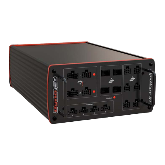
DynoWare RT Electronics DYNOWARE RT ELECTRONICS The DynoWare RT electronics consists of a main module and a speed pickup. Optional modules include the Air Fuel Ratio (AFR) module and the Eddy Current Brake (ECB) driver. Use this section to identify the modules and connections. More detailed information for configuring the DynoWare RT electronics can be found in the ... -
Page 13: Main Module Connections
Do not press this button unless drum 2 speed inputs and Instructions instructed to do so by a Dynojet digital brake outputs. Technician. This button may need to be pressed to update the device. Version 5 DynoWare RT Upgrade for Model 424x Dynamometers Installation Guide... -
Page 14: Network Connections
The Dynojet DynoWare RT dyno electronics connects to your computer directly or over a Local Area Network. If you have an existing network, connect the DynoWare RT main module to a router or a network switch on your network. If you don't have an existing network, you can create a network for the DynoWare RT by connecting the main module to a router. -
Page 15: Without Eddy Current Brake
RAKE This chapter will walk you through removing the DynoWare EX and installing the DynoWare RT upgrade on your model 424 Dynojet Dynamometer without the eddy current brake. To ensure safety and accuracy in the procedures, perform the procedures as they are described. -
Page 16: Unpacking The Dynoware Rt Parts
P/N 76950547 remote atmos assembly cable, CAN dyno user, 15' P/N 66400011 P/N 76950798 *included with the optional air fuel module speed pickup (2) cable, CAN control adapter P/N 68300002 P/N 76950807 DynoWare RT Upgrade for Model 424x Dynamometers Installation Guide... -
Page 17: Remove The Dynoware Ex Electronics
15 Remove the 3/8 x 1.25-inch button-head bolt securing the left drum guard on the 4WD dyno. Slide the drum guard out from under the runner mount and set aside. 16 Continue with “Removing the Pickup Card, Bracket, and Cable” on page 2-6. Version 5 DynoWare RT Upgrade for Model 424x Dynamometers Installation Guide... - Page 18 4WD drum guard 4WD runner mount runner extension runner extension runner extension support leg Figure 2-1: Remove the Pit Covers DynoWare RT Upgrade for Model 424x Dynamometers Installation Guide...
-
Page 19: Removing The Logo Panels-Above Ground Dynos
Remove the logo panels and set aside. You may wish to remove the bridge covers for easier access to the air hoses. bridge covers logo panel Figure 2-2: Remove the Logo Panels Version 5 DynoWare RT Upgrade for Model 424x Dynamometers Installation Guide... -
Page 20: Removing The Pickup Card, Bracket, And Cable
Be sure to mark both the stationary and 4WD dyno bracket location. Remove the two screws securing the bracket and set aside. Remove the bracket. mark bracket position mark bracket position Figure 2-3: Removing the Pickup Card Bracket DynoWare RT Upgrade for Model 424x Dynamometers Installation Guide... -
Page 21: Removing The Breakout Board
Disconnect the brake solenoid leads from the Breakout board. These are the black wires running from the air solenoid to the Breakout board. DynoWare RT does not support the Breakout board controlled Gen 4 (AFR-4) air pump and O2 sensors used with DynoWare EX and WinPEP 7. Disconnect and remove the Gen 4 relay and wires from the Breakout board. -
Page 22: Dynoware Rt Installation
C H A P T E R 2 DynoWare RT Installation DYNOWARE RT INSTALLATION Use the following instructions to install the DynoWare RT electronics and wiring to your above ground or in ground model 424 dyno. You will need the following part: •... -
Page 23: Aligning The Speed Pickup Card
AD631 Figure 2-8: Align the Optical Pickup Card Tab Version 5 DynoWare RT Upgrade for Model 424x Dynamometers Installation Guide... -
Page 24: Cable Routing
Linx to the DynoWare RT *the Linx system is an optional accessory H - 76950798 CAN dyno user cable, 15' connects the air fuel module to the DynoWare RT using the CAN adapter cable *included with optional air fuel module... - Page 25 Cable Routing cable brief routing description I - 76950807 CAN control cable, adapter, 2' connects the DynoWare RT to the CAN dyno user cable J - 76423045 CAN termination plug connects to the last CAN cable in the CAN network...
- Page 26 Remove the 4WD dyno speed pickup cable from the cable track and discard. Continue with “Routing the Cables” on page 2-13. disconnect brake signal wires C 026 Figure 2-10: 4WD Movement Board DynoWare RT Upgrade for Model 424x Dynamometers Installation Guide 2-12...
-
Page 27: Routing The Cables
BRK IN terminals on the 4WD board. Figure 2-11: 4WD Movement Board—Connect Speed Pickup/Brake Wires without Linx Option Version 5 DynoWare RT Upgrade for Model 424x Dynamometers Installation Guide 2-13... - Page 28 11 Insert the sockets into the housing (P/N 44329902). The position of the sockets in the housing is not critical. 12 Attach the two-pin connector on the speed pickup/brake cable (F) to the connector on the brake solenoid wires. DynoWare RT Upgrade for Model 424x Dynamometers Installation Guide 2-14...
- Page 29 DynoWare RT module. 14 Route the Linx detect sensor cable (G) from the second cable track, through the pit conduit (if in ground), and connect to Linx 1 on the back of the DynoWare RT module. 15 Use the CAN adapter cable (I), the CAN dyno user cable (H), and the CAN termination plug (J) when using the optional air fuel module.
- Page 30 C H A P T E R 2 Cable Routing Figure 2-14: Routing the Cables DynoWare RT Upgrade for Model 424x Dynamometers Installation Guide 2-16...
-
Page 31: Testing
M O D E L 4 2 4 D Y N O W A R E R T U P G R A D E W I T H O U T E D D Y C U R R E N T Testing TESTING Turn on the DynoWare RT module. This switch is located on the rear of the module. Using the pendant, release the brake. -
Page 32: Replace Covers
10 Secure the 4WD bridge cover using the two 1/4 x 5/8-inch torx head bolts and two 3/8 x 1.5-inch flange bolts removed earlier. 11 Secure the left forward pit cover using the two 3/8-16 x 3-inch bolts and seven 3/8-16 x 1/2-inch bolts removed earlier. DynoWare RT Upgrade for Model 424x Dynamometers Installation Guide 2-18... - Page 33 4WD drum guard 4WD runner mount runner extension runner extension runner extension support leg Figure 2-16: Install the Pit Covers Version 5 DynoWare RT Upgrade for Model 424x Dynamometers Installation Guide 2-19...
- Page 34 ANEL BOVE ROUND YNOS Secure each logo panel using the five screws removed earlier. Replace the bridge covers if removed. bridge covers logo panel Figure 2-17: Install the Logo Panels DynoWare RT Upgrade for Model 424x Dynamometers Installation Guide 2-20...
-
Page 35: With Eddy Current Brake
RAKE This chapter will walk you through removing the DynoWare EX and installing the DynoWare RT upgrade on your model 424 Dynojet Dynamometer with eddy current brakes. To ensure safety and accuracy in the procedures, perform the procedures as they are described. -
Page 36: Unpacking The Dynoware Rt Parts
P/N 42900000 35' (2) P/N 76950547 connector cable, IR temp sensor (2) P/N 44329902 P/N 76950628 socket (2) cable, load cell (2) P/N 44359120 P/N 76950629 DynoWare RT Upgrade for Model 424x Dynamometers Installation Guide... - Page 37 3/8 x 1/2L (8) P/N 68300002 P/N A10Z 2-304A pendant assembly DynoWare RT speed P/N 76100007 upgrade kit, split disk (2) P/N 78100057 see list of parts below Version 5 DynoWare RT Upgrade for Model 424x Dynamometers Installation Guide...
- Page 38 C H A P T E R 3 Unpacking the DynoWare RT Parts part description part description The following parts are included in the DynoWare RT Speed Upgrade Kit P/N 78100057 screw, 1/4-20 x 1-1/8", inner bracket, speed pickup card socket-head (2) P/N 21600085...
-
Page 39: Remove The Dynoware Ex Electronics
Continue with “Removing the Theta Controller—In Ground Dynos” on page 3-7. remove bolt securing cover to support leg left pit cover AD633 eddy current brake pit cover Figure 3-1: Remove the Pit Covers Version 5 DynoWare RT Upgrade for Model 424x Dynamometers Installation Guide... -
Page 40: Removing The Ecb Top Covers And Logo Panel-Above Ground Dynos
Remove the eight screws securing the large top cover and set aside. Remove the large top cover and set aside. small top cover large top cover logo panel AD634 Figure 3-2: Remove the Logo Panel and ECB Top Covers DynoWare RT Upgrade for Model 424x Dynamometers Installation Guide... -
Page 41: Removing The Theta Controller-In Ground Dynos
Remove the four screws securing the theta controller to the bracket and set aside. Remove the theta controller. theta controller AD635 theta controller Figure 3-3: Remove the Theta Controller—In Ground Dynos Version 5 DynoWare RT Upgrade for Model 424x Dynamometers Installation Guide... -
Page 42: Removing The Theta Controller-Above Ground Dynos
Remove the four screws securing the theta controller to the brake and set aside. Remove the theta controller. theta controller AD636 theta controller Figure 3-4: Remove the Theta Controller—Above Ground Dynos DynoWare RT Upgrade for Model 424x Dynamometers Installation Guide... -
Page 43: Removing The Pickup Card And Breakout Board-In Ground Dynos
Note: Remove the pickup card bracket, pickup card, and speed pickup cable from both the stationary and 4WD dyno. DynoWare RT does not support the Breakout board controlled Gen 4 (AFR-4) air pump and O2 sensors used with DynoWare EX and WinPEP 7. Disconnect and remove the Gen 4 relay and wires from the Breakout board. - Page 44 Note: Remove the pickup card bracket, pickup card, and speed pickup cable from both the stationary and 4WD dyno. DynoWare RT does not support the Breakout board controlled Gen 4 (AFR-4) air pump and O2 sensors used with DynoWare EX and WinPEP 7. Disconnect and remove the Gen 4 relay and wires from the Breakout board.
- Page 45 Remove the four nuts securing the Breakout board to the bumpers and remove the board. Remove the four screws securing the bumpers to the dyno and remove the bumpers. AD639 bumper breakout board Figure 3-7: Remove the Breakout Board Version 5 DynoWare RT Upgrade for Model 424x Dynamometers Installation Guide 3-11...
-
Page 46: Dynoware Rt Installation
C H A P T E R 3 DynoWare RT Installation DYNOWARE RT INSTALLATION Use the following instructions to install the DynoWare RT electronics and wiring. You will need the following parts: • 134490301 Nut, 8-32, with Lock Washer (8) •... -
Page 47: Installing The Split Disk And Speed Pickup Card
Secure the inner bracket to the dyno using two 3/8-16 x 1-inch bolts and two 3/8-inch nuts. split disk inner bracket split disk Figure 3-9: Installing the Split Disk and Speed Pickup Card Version 5 DynoWare RT Upgrade for Model 424x Dynamometers Installation Guide 3-13... -
Page 48: Aligning The Speed Pickup Card
Be sure to tighten the inner bracket mounting screws once aligned. Attach the black 3-pin connector from the DynoWare RT speed pickup/brake cable (P/N 76950547) to the speed pickup card on the stationary and 4WD dyno. -
Page 49: Installing The Eddy Current Brake Driver-Above Ground Dynos
Install the eddy current brake driver to the cover using four 8-32 nuts. eddy current brake driver eddy current brake driver Figure 3-12: Install the Eddy Current Brake Driver—Above Ground Version 5 DynoWare RT Upgrade for Model 424x Dynamometers Installation Guide 3-15... -
Page 50: Installing The Eddy Current Brake Driver-In Ground Dynos
Install the eddy current brake driver to the bracket using four 8-32 nuts. eddy current brake driver eddy current brake driver Figure 3-14: Install the Eddy Current Brake Driver—In Ground DynoWare RT Upgrade for Model 424x Dynamometers Installation Guide 3-16... -
Page 51: Cable Routing
G - 76950628 IR temp sensor cable adapter connects the temp sensor to the eddy current brake driver H - 76950629 load cell cable adapter connects the load cell to the eddy current brake driver Version 5 DynoWare RT Upgrade for Model 424x Dynamometers Installation Guide 3-17... - Page 52 *the Linx system is an optional accessory J - 76950791 CAN control cable, 15' connects the eddy current brake driver (on the stationary dyno) to the DynoWare RT using the CAN adapter cable or CAN network cable chain K - 76950791 CAN control cable, 15'...
-
Page 53: Removing The Dynoware Ex Cables
Breakout board. Do not disconnect the sensors from the eddy current brake. Remove the 4WD temperature sensor cable from the cable track. Coil this cable up and place it near the 4WD dyno. Version 5 DynoWare RT Upgrade for Model 424x Dynamometers Installation Guide 3-19... - Page 54 12 Remove the 4WD dyno speed pickup cable from the cable track and discard. 13 Continue with “Routing the Cables” on page 3-21. disconnect brake signal wires C 026 Figure 3-16: 4WD Movement Board DynoWare RT Upgrade for Model 424x Dynamometers Installation Guide 3-20...
-
Page 55: Routing The Cables
BRK IN terminals on the 4WD board. Figure 3-17: 4WD Movement Board—Connect Speed Pickup/Brake Wires without Linx Option Version 5 DynoWare RT Upgrade for Model 424x Dynamometers Installation Guide 3-21... - Page 56 15 If not already done, attach the three-pin connector on the speed pickup/brake cable (F) to the speed pickup card installed on the eddy current brake. DynoWare RT Upgrade for Model 424x Dynamometers Installation Guide 3-22...
- Page 57 DynoWare RT module. 17 Route the Linx detect sensor cable (I) from the second cable track, through the pit conduit (if in ground), and connect to Linx 1 on the back of the DynoWare RT module. 18 Connect the CAN pendant cable (D) to the DynoWare RT module.
- Page 58 28 Connect the power cable (O) to each eddy current brake driver. This cable was unplugged from the theta controller. 29 Connect the power cable (A) to the DynoWare RT module. Plug the power cable into your power source. 30 Connect the primary/secondary pickup cable (E) to the DynoWare RT module.
- Page 59 M O D E L 4 2 4 D Y N O W A R E R T U P G R A D E W I T H E D D Y C U R R E N T B R A K E Cable Routing Figure 3-20: Routing the Cables—One Eddy Current Brake Version 5 DynoWare RT Upgrade for Model 424x Dynamometers Installation Guide 3-25...
- Page 60 C H A P T E R 3 Cable Routing Figure 3-21: Routing the Cables—Two Eddy Current Brakes DynoWare RT Upgrade for Model 424x Dynamometers Installation Guide 3-26...
-
Page 61: Testing
M O D E L 4 2 4 D Y N O W A R E R T U P G R A D E W I T H E D D Y C U R R E N T B R A K E Testing TESTING Turn on the DynoWare RT module. This switch is located on the rear of the module. Using the pendant, release the brake. -
Page 62: Replace Covers
Secure the large top cover using the eight screws removed earlier. Secure the logo panel using the six screws removed earlier. small top cover large top cover logo panel AD634 Figure 3-23: Install the Logo Panel and ECB Top Covers DynoWare RT Upgrade for Model 424x Dynamometers Installation Guide 3-28... -
Page 63: Replacing The Covers-In Ground Dynos
3/8-inch flat washers removed earlier. replace bolt securing cover to support leg left pit cover AD633 eddy current brake pit cover Figure 3-24: Install the Pit Covers Version 5 DynoWare RT Upgrade for Model 424x Dynamometers Installation Guide 3-29... -
Page 64: Load Cell Calibration
Click Dyno Control from the Application Launcher. Verify you are connected to the DynoWare RT. Note: For more information on connecting to the DynoWare RT, refer to the Power Core Quick Start Guide included with your dyno or the Power Core Help. - Page 65 Note: Dynojet recommends you secure the calibration arm using the bolt pattern closest to the end of the arm unless space constraints in your dyno room do not allow you to.
- Page 66 Refer to step 9 and Figure 3-29 on page 3-33 for calibration arm installation instructions. direction of torque direction of rotation direction of rotation Figure 3-28: Calibration Bar Placement DynoWare RT Upgrade for Model 424x Dynamometers Installation Guide 3-32...
- Page 67 Figure 3-29: Install Calibration Arm and Weights Version 5 DynoWare RT Upgrade for Model 424x Dynamometers Installation Guide 3-33...
- Page 68 12 Remove the calibration arm and weights and click Finish. Figure 3-31: Calibration Is Complete Window Refer to your Power Core Help for more information on creating a torque gauge and viewing torque values. DynoWare RT Upgrade for Model 424x Dynamometers Installation Guide 3-34...
- Page 69 HAPTER ASIC PERATION The Dynojet dynamometer gives you the state of the art technology, durability, and accuracy that you need. Dynojet’s advanced engineering delivers the precise horsepower measurements a technician needs to make quick and accurate evaluations of engine performance and drivetrain problems.
-
Page 70: Loading The Vehicle
10M #, car tie-down, high 2 x 21" (4) performance, 2" x 10' (2) P/N 30AS21 P/N 500-C10W/S long axle strap, 10M #, 2 x 72" (4) P/N 30AS72 DynoWare RT Upgrade for Model 424x Dynamometers Installation Guide... - Page 71 • If the vehicle has a manual transmission, place it in gear. Set the vehicle’s emergency brake. Secure the non-drive wheels using the provided tire chocks. Do not use tire chocks for four wheel drive vehicles. Version 5 DynoWare RT Upgrade for Model 424x Dynamometers Installation Guide...
- Page 72 With four wheel drive vehicles, always use longitudinal and cross straps at the front of the vehicle. rear wheel drive front wheel drive four wheel drive Figure 4-2: Attach the Tie-down Straps DynoWare RT Upgrade for Model 424x Dynamometers Installation Guide...
- Page 73 13 Press the accelerator pedal so the drums begin turning slowly. While the drums are slowly turning, verify the stability of the vehicle. 14 Check all the straps and ensure the vehicle is tracking straight on the dyno. Version 5 DynoWare RT Upgrade for Model 424x Dynamometers Installation Guide...
-
Page 74: Connecting The Rpm Pickup
720/8=90 degrees. Optional Optical RPM Sensor Attach the sensor wire to the RPM port on the DynoWare RT module. The other end of the wire attaches to the Optical Sensor. Set the degrees between plug fires to 360° in Power Core. Refer to the Optical RPM Sensor Installation Guide (P/N 98200044). -
Page 75: Connecting The Secondary Inductive Pickup
Clip the secondary inductive pickup around one spark plug wire. Route the inductive pickup cable to the RPM port on the DynoWare RT module making sure the cable is clear of devices that produce electronic noise (spark plug wires, coil wire, coil etc.). -
Page 76: Connecting The Primary Inductive Pickup
Clip the primary inductive pickup around the negative side of the coil. Route the primary wire cable to the RPM port on the DynoWare RT module making sure the cable is clear of devices that produce electronic noise (spark plug wires, coil wire, coil etc.). -
Page 77: Grounding The Vehicle
Secure the grounding bracket to this location using one 1/4-20 x 1/2-inch screw. Attach the vehicle ground cable to an exhaust bolt or engine bolt on the vehicle. Attach the vehicle ground cable to the grounding bracket. Version 5 DynoWare RT Upgrade for Model 424x Dynamometers Installation Guide... -
Page 78: Pre-Run Inspection
Engine exhaust contains poisonous carbon monoxide gas. Breathing it could cause death. Operate machine in well ventilated area. DynoWare RT Upgrade for Model 424x Dynamometers Installation Guide 4-10... -
Page 79: Engine Warm Up
• Fix any fuel, oil, or coolant leaks that may have shown up after engine warm up and check the carburetor for leaks. • Any loud or unusual engine noises or excessive exhaust smoke should be resolved before continuing. Version 5 DynoWare RT Upgrade for Model 424x Dynamometers Installation Guide 4-11... -
Page 80: Making A Test Run
CAUTION Using the vehicle’s own brakes to slow or stop the drum at speeds over 30 m.p.h. can severely overheat the brake parts. Dynojet dynamometers with the air brake or eddy current brake accessory can be used to slow the vehicle and drum to a full stop at any speed. -
Page 81: Preventative Maintenance
Lithium 12 Hydroxy Stearate Petroleum thickness NLGI 2 operating temperature -29°C to 93°C, intermittent to 121°C (-20°F to 200°F, intermittent to 250°F) EP additive examples Mobil Mobilith AW-2 Version 5 DynoWare RT Upgrade for Model 424x Dynamometers Installation Guide 4-13... - Page 82 AB095 brake pressure gauge 100psi (690kPA) Figure 4-6: Verify the SAAR Brake Pressure and Adjust the Regulator DynoWare RT Upgrade for Model 424x Dynamometers Installation Guide 4-14...
- Page 83 Note: The mounting bracket shown is used with the SAAR upgrade. Factory installed SAAR brakes use a slightly different bracket. brake shoe drum measure gap AB094 Figure 4-7: Measure the Gap Between the Brake Shoe and Drum Version 5 DynoWare RT Upgrade for Model 424x Dynamometers Installation Guide 4-15...
- Page 84 If you cannot adjust the brakes to specification, you will need new brake shoes. Contact Dynojet for more information. air can rod upper nut brake actuating tube BR032 lower nut Figure 4-8: Adjust the Brake Shoe Clearance DynoWare RT Upgrade for Model 424x Dynamometers Installation Guide 4-16...
- Page 85 • Inspect the hoses connecting the hydraulic motor to the ram. Replace as necessary (P/N 11100000). • Inspect the 4WD dyno movement rails for debris once per month. Clear any debris from the rails. Version 5 DynoWare RT Upgrade for Model 424x Dynamometers Installation Guide 4-17...
-
Page 87: Index
IR temp sensor cable 3-17, 3-24 document part number 1-1 dyno electronics 1-4 DynoWare EX removing 2-3, 3-5 removing breakout board 2-7, 3-9, 3-10 removing pickup card 2-6, 3-9, 3-10 DynoWare RT Upgrade for Model 424x Dynamometers Installation Guide Index-i... - Page 88 CAN dyno user 2-10, 3-18 zero calibration 3-30 CAN pendant 2-10, 2-15, 3-17, 3-23 CAN termination plug 2-11, 3-18 controller cable 3-18 DynoWare RT power 2-10, 2-15, 3-17, 3-24 eddy current brake power 3-18 DynoWare RT Upgrade for Model 424x Dynamometers Installation Guide Index-ii...
Need help?
Do you have a question about the Dynoware RT and is the answer not in the manual?
Questions and answers